
How to Choose a Mold Temperature Controller
Table of Contents
A 32-cavity PC connector housing mold ran at 68 °C instead of the 85 °C setpoint. The water temperature controller was sized at 6 kW for a 400 kg tool, the pump lost 1.2 bar through an oversized manifold, and cavity temperature drifted 8 to 12 °C across the day. Shrinkage scatter climbed to 0.12%, 900 housings failed dimensional inspection in week one, and the toolmaker burned 16 hours chasing warpage that traced back to the controller spec.
A mold temperature controller (MTC) circulates heated water or oil through the mold to hold the cavity at a target temperature. It decides shrinkage, warpage, crystallinity, surface gloss and cycle time, so a wrong choice repeats defects in every cavity.
This guide covers MTC types, temperature ranges, heating power, pump flow, control precision, circuit counts, material mold temperatures, cooling circuit matching, a sizing example and failure modes. Figures are typical industry values from DME and moldmaking practice; verify each against your resin data sheet.
The Snapshot
- A ±5 °C mold temperature swing shifts shrinkage by ±0.05 to 0.1% and can push a ±0.1 mm tolerance out of spec.
- Water units cover 20 to 160 °C, oil units 100 to 250 °C, and water above 100 °C needs 1.6 to 6.2 bar of loop pressure.
- Heating rule of thumb: 1.5 to 3 kW per 100 kg of mold steel for a 45 to 60 minute warm-up, plus a 20 to 30% margin.
- Flow of 20 to 40 L/min per circuit at 2 to 4 bar head covers most 8 to 32 cavity molds.
- Control precision is ±1 °C at the sensor; cavity temperature can still vary 5 to 10 °C from setpoint on a poor channel layout.
- An undersized unit adds 60 to 90 minutes to every warm-up.
Why Mold Temperature Controller Selection Fails
Most MTC mistakes are sizing and specification errors made at the RFQ stage, not machine failures. The most common is buying the same unit as the last mold regardless of mold mass, resin or cavity count. A 3 kW unit that served a 150 kg tool will not heat a 500 kg tool in the same warm-up window.
The second failure is ignoring the process window. Amorphous resins like PC and ABS need stable temperature for consistent shrinkage; semi-crystalline resins like POM, PA66 and PBT need a narrow band for repeatable crystallinity. Run POM at 60 °C when the data sheet calls for 80 to 100 °C, and shrinkage, warpage and weld lines all move.
The third failure is treating the MTC as separate from the mold. The controller delivers only what the channels carry: a balanced 10 to 14 mm layout with turbulent flow moves heat, a 6 mm channel at 4 L/min turns the unit into a decorative box.
Finally, nobody verifies temperature at the cavity. The display and inlet sensor read 85 °C, but the cavity wall sits at 76 °C when channels sit 40 mm from the surface. Measure at the cavity with thermocouple probes at T1; one verification run costs far less than 900 scrapped housings.
Water, Oil and Electric Mold Temperature Controllers
Three families cover nearly every molding program below 250 °C. The choice follows the required mold temperature first, then heat transfer, then running cost.
Water temperature controllers
Water units cover 20 to 160 °C: open-loop 20 to 90 °C, pressurized closed-loop 120 to 160 °C at 1.6 to 6.2 bar. Water transfers heat 4 to 5 times better than oil, roughly 0.6 W/m·K against 0.13 W/m·K, and is the default for PC, ABS, POM, PA and PP molds up to about 140 °C. Hard water above 60 °C scales channels and cuts heat transfer.
Oil temperature controllers
Oil units run 100 to 250 °C for PEEK, PSU, PEI, LCP and high-temperature PA grades, holding temperature at lower system pressure than pressurized water. The trade is slower response and maintenance: oil oxidizes above 180 °C, so change it every 12 to 24 months.
Electric heating
Electric mold heating uses cartridge or band heaters in the mold, driven by a control cabinet, and reaches 300 °C and above. It suits hot runners, compression molds and short runs of high-temperature resins. The trade is slow response, uneven heating without careful layout, and cartridge burnout that stops the mold.
| Type | Temperature Range | Heat Transfer | Best For | Watch Out |
|---|---|---|---|---|
| Water MTC | 20-160 °C (90 °C open, 120-160 °C pressurized) | ~0.6 W/m·K, 4-5x oil | PC, ABS, POM, PA, PP, most programs under 140 °C | Hard water scales channels above 60 °C |
| Oil MTC | 100-250 °C | ~0.13 W/m·K, slower response | PEEK, PSU, PEI, LCP, high-temp PA | Oil oxidizes above 180 °C, change every 12-24 months |
| Electric heating | Up to 300 °C+ | Direct, uneven without layout care | Hot runners, compression molds, short runs | Cartridge burnout stops the mold |
← swipe to scroll →
Table: typical industry figures; verify against your program.

Temperature Range and Heating Power
Set the range from the resin data sheet: PC runs 80 to 120 °C, POM 80 to 100 °C, PA66 80 to 120 °C, PBT 60 to 100 °C and PP 40 to 60 °C. Pick a unit whose range covers the window with margin.
Heating power from mold mass
Steel absorbs about 460 J per kg per kelvin. A 400 kg mold heated from 25 °C to 80 °C needs 400 x 460 x 55, about 10.1 MJ. In 60 minutes that is 2.8 kW average. Add 20 to 30% for losses to the platen and shop air, and the practical figure lands near 3.6 kW, so a 6 kW unit is the standard size.
Heating power from melt heat
The melt dumps heat into the mold every cycle: amorphous resins release 300 to 400 kJ/kg as they cool, semi-crystalline resins 500 to 700 kJ/kg with crystallization latent heat. Multiply hourly throughput in kg by the figure and divide by 3600 for the average load in kW; 8 kg/h of PP is roughly 1.1 to 1.6 kW for the cooling side.
Standard sizes
Commercial MTCs step in 3, 6, 9, 12, 18 and 24 kW. Match the calculated need to the next size up. Never size heating equal to the steady-state load, or warm-up takes the whole shift. Heating covers warm-up; cooling covers the cycle load, and the two are almost never equal.
Pump Flow, Pressure and Control Precision
The pump moves the heat, and flow decides uniformity. Two numbers matter: flow in L/min and head in bar. Flow carries heat; head pushes water through channels and fittings.
Most 8 to 32 cavity molds run on 20 to 40 L/min per circuit at 2 to 4 bar. Thin-wall molds, long channels and 6 to 8 mm bores need 4 to 6 bar to hold turbulent flow. Laminar flow leaves a stagnant film that blocks heat transfer, so target a Reynolds number above 4000; at 10 mm bore and 30 °C water that means roughly 18 L/min per parallel circuit.

Control precision is quoted at the sensor, and ±1 °C is the standard claim for a tuned unit. The cavity wall is not the sensor: channel distance, steel mass and flow distribution sit between them, so a ±1 °C controller can deliver ±5 to 10 °C at the cavity on a poorly channeled mold. Verify at T1 with probes or thermal imaging. A hunting PID loop swings supply temperature 3 to 5 °C and shows up as gloss variation on polished parts.
Single, Dual and Triple Circuits vs Cavity Count
The circuit count decides how many independent temperature zones the mold gets. A single-circuit unit feeds one supply and one return, so every channel shares one temperature; it suits 8 to 16 cavity tools with uniform geometry.
A dual-circuit unit runs two independent zones, for a core and cavity at different temperatures or a gate side hotter than the ejection side. Automotive connector housings and thin-wall caps routinely run core at 60 °C and cavity at 80 °C. A dual unit also runs two resin families without re-plumbing.
Triple-circuit units add a zone for three-plate or stack molds, or a deep core on its own temperature. The rule: one circuit per distinct temperature zone, not one per cavity. A 64-cavity mold still runs one circuit when all cavities demand the same temperature. Multipliers belong to flow, not to circuits.
Check the pump curve before adding circuits. Splitting one 40 L/min pump across two circuits gives 20 L/min per zone, below the turbulent threshold for many layouts. If two zones each need 25 L/min, buy a unit with a pump per zone.
Recommended Mold Temperatures by Material
Mold temperature is a process variable with a resin-specific window. Operating inside the window keeps shrinkage, crystallinity and surface finish repeatable; outside it, no process tuning removes the defects. The table lists typical windows and the controller family that covers each.
| Resin | Mold Temperature | Controller Type | Why the Window Matters |
|---|---|---|---|
| PP | 40-60 °C | Water, open loop | Low window, warpage control on thin parts |
| ABS | 60-80 °C | Water | Gloss, weld lines, shrinkage consistency |
| PMMA | 60-80 °C | Water | Transparency, sink marks on thick sections |
| POM | 80-100 °C | Water | Crystallinity drives shrinkage and wear on moving parts |
| PBT | 60-100 °C | Water | Crystallization rate, housing flatness |
| PC | 80-120 °C | Water, pressurized above 100 °C | Shrinkage consistency, internal stress, crack resistance |
| PA66 | 80-120 °C | Water, pressurized above 100 °C | Crystallinity, dimensional stability after conditioning |
| LCP | 80-120 °C | Water or oil | Skin-core structure, anisotropic shrinkage |
| PEEK | 160-200 °C | Oil | Crystallinity window, part toughness |
← swipe to scroll →
Table: typical industry figures from DME and resin data sheets; verify against your grade.
Semi-crystalline resins punish drift harder than amorphous ones: a PA66 housing molded at 90 °C instead of 110 °C shows lower crystallinity, higher post-mold shrinkage and weaker weld lines. The material guides at the end give the full window for each family.
Matching the MTC to the Mold Cooling Circuit
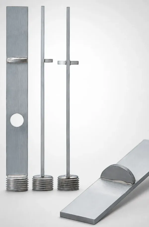
The MTC is only as good as the channel layout it feeds. Channel spacing of 2 to 2.5 times the channel diameter, channels 15 to 25 mm from the cavity wall, and parallel circuits with equal branch lengths turn the spec into real cavity temperature.
Two checks decide whether the plumbing supports the unit. First, sum the flow resistance of channels, manifolds, hoses and fittings, and confirm the pump still delivers turbulent flow at the far cavity. Second, confirm the return water temperature rises less than 3 to 5 °C per circuit. A bigger rise means flow is too low and far cavities run hot. The layout rules behind both checks are covered in our mold cooling channel design guide.
DieStrike supplies the cooling-side hardware that completes the loop: baffles, bubblers, cascade pipes, thermal pins, water manifolds and plugs for channels down to 3 mm, sized in the free 24-hour DFM review. See the mold heating and cooling components page for the full line.
Worked Sizing Example: 16-Cavity PP Cap Mold
Work a 16-cavity PP cap mold through the full sizing sequence. The mold weighs 300 kg, the part is 2.2 g, the runner adds 4.8 g, the cycle is 18 s, and the target mold temperature is 50 °C.
Heating power from mass: the mold rises from 25 °C to 50 °C, a 25 K rise. That is 3.45 MJ, or 1.28 kW over a 45-minute warm-up. Add 25% for losses and the requirement is about 1.6 kW. The melt adds load: 200 shots per hour at 7 g is 1.4 kg/h, and PP at roughly 600 kJ/kg adds 0.23 kW. Total heating need is about 1.8 kW, so the next standard size up is a 3 kW water unit.
Cooling capacity: the steady-state load is melt heat plus motor and shear heat, roughly 0.3 to 0.5 kW, which the 3 kW unit removes with ease. Flow: the mold runs one 10 mm circuit, and turbulent flow at 30 °C needs about 18 L/min, so a 30 L/min pump at 3 to 4 bar covers the mold with margin for a second zone.
Verify at T1: inlet 50 °C, return under 54 °C, cavity surface 46 to 54 °C at four points, cycle at target. If return temperature rises past 5 °C, raise the flow before raising the setpoint. That sequence catches the 68 °C failure from the opening of this guide before it becomes 900 scrap parts.
Failure Modes and Maintenance
MTC failures announce themselves as temperature drift, pressure alarms and quality shifts long before they stop the press. The common modes are pump seal leaks, heater burnout, fouled channels, thermocouple drift and sticking control valves.
Heater burnout shows as slow warm-up and one phase drawing less current; check element currents monthly. Fouling is the silent one: scale and oil carbon deposit on channel walls, heat transfer drops, and the controller runs longer and hotter to hold setpoint. Scale 0.5 mm thick cuts heat transfer by roughly 20 to 40%; the fix is water treatment, descaling every 6 to 12 months and oil changes every 12 to 24 months. Thermocouple drift of 2 to 5 °C makes the controller chase a false reading, so calibrate at each PM. A sticking solenoid valve swings supply temperature 3 to 5 °C; listen for chatter during warm-up.

Log the drift between display temperature and cavity temperature at every PM visit. A consistent 5 °C gap is a channel or sensor problem, not a controller problem. Thermal-system upkeep follows the same discipline as the rest of the mold; the parallel list of routine checks lives in the hot runner maintenance checks.
FAQ: Mold Temperature Controller Selection
Q1. What size mold temperature controller do I need?
Size heating from mold mass: weight in kg times 460 times the temperature rise in kelvin, divided by warm-up seconds, plus 20 to 30% for losses. Round up to 3, 6, 9, 12, 18 or 24 kW. A 400 kg mold heating 55 K in 60 minutes needs about 3.6 kW, so a 6 kW unit.
Q2. Water or oil mold temperature controller?
Choose by required temperature. Up to 120 °C, use water. Between 120 and 160 °C, use pressurized water at 1.6 to 6.2 bar. Above 160 °C up to 250 °C, use oil. Water transfers heat 4 to 5 times better than oil, so oil is justified by temperature, not habit.
Q3. How many circuits does my mold need?
One circuit per distinct temperature zone. A uniform 16-cavity mold runs one circuit. A core and cavity at different temperatures need two. A three-plate or stack mold with a separate core zone needs three. Cavity count does not set the circuit count; flow rate does.
Q4. What happens if mold temperature is too low?
Shrinkage becomes inconsistent, semi-crystalline parts show lower crystallinity and higher post-mold shrinkage, weld lines weaken, and thin walls fill with more pressure. On PC, low mold temperature raises internal stress and crack risk. Each 5 °C below the window typically shifts shrinkage by 0.05 to 0.1%.
Q5. How do I check the mold really reaches setpoint?
Measure at the cavity, not the display. Place thermocouple probes at four cavity points at T1 trial, or use thermal imaging during warm-up. Confirm return water rises less than 3 to 5 °C per circuit. Log the gap between display and cavity at every PM.
The Bottom Line
A mold temperature controller is sized in three numbers: temperature range from the resin, heating power from the mold mass, and flow from the channel layout. Get the type and range right, put 20 to 30% margin on heating, keep one circuit per zone, and verify cavity temperature at T1. That sequence prevents the 900-part scrap week from the opening of this guide.
Send us your part drawing and we will return a mold temperature control recommendation with the cooling channel layout and a cost breakdown in 48 hours.
KEEP READING
Related Reading
5 Mold Cooling Channel Design Tips for Faster Cycles
Mold maker's 5 cooling channel design rules: channel-to-cavity distance 2-2.
Read articleArticle5 Shrinkage Compensation Rules for Mold Design
Shrinkage compensation decides mold accuracy. Five rules: material rates from 0.3% to 2.
Read articleArticle5 Ways to Reduce Mold Cost Without Cutting Quality
Five proven ways to reduce injection mold cost without cutting quality: DFM before quoting, right-sized cavity count,…
Read articleArticle7 Gate Design Best Practices for Balanced Filling
Mold maker's 7 gate design rules for balanced multi-cavity filling: gate depth 50-80% of wall thickness, land 0.5-1.
Read articleNEXT STEP
Ready to Start Your Mold?
Send us your element dimensions or part numbers — our team responds within 24 hours with pricing and lead time.

Written by
Ray ChanMold Buyer's Guide Author · Precision Mold Manufacturing Specialist. Ray helps global importers, distributors and OEMs source factory-direct molds and mold parts.