
Thermoplastic Elastomer (TPE) Injection Molding Guide
Table of Contents
A TPE overmold that delaminates in the customer's hand rarely fails alone. It takes the two-shot mold, the tooling program, and the production run down with it — and the root cause was usually decided on the drawing board: a polarity mismatch between the soft TPE and the hard substrate, a mold temperature set below the bond window, or a soft wall drafted at 0.5° that sticks to the core on every cycle. First-trial scrap rates of 5-15% are typical industry experience on TPE parts, and most of that scrap is tool design, not resin.
Thermoplastic elastomer (TPE) is the fastest-growing soft-material family in injection molding because it combines rubber-like elasticity with melt-processable thermoplastics — a combination that turns soft-touch grips, seals, and wearable straps into standard injection molding work. Global TPE demand sits in the multi-million-ton range, driven by automotive interiors, consumer electronics, and medical devices (industry estimates). The same softness that makes the material feel good in the hand makes it hard to eject, easy to flash, and unforgiving at bond interfaces — which is why this guide reads TPE from the mold side, not the chemistry side.
This guide is written for the people who buy and build the tool: mold buyers, tooling engineers, and manufacturing engineers. It maps the properties that drive mold decisions, walks the design rules for TPE tooling — including the two-shot and rotary mold designs that overmolding demands — and ends with defects traced to their mold-side root causes. Processing numbers follow typical published values for injection-molding grades. Test methods are cited where they matter.
The Snapshot
- TPE spans Shore 5A to 60D: gel-like seal grades to stiff TPU grades (typical range). Hardness decides the ejection system before it decides anything else.
- Melt temperature window is 170-230°C by family; mold temperature 20-50°C for standard parts, 40-50°C when the TPE must bond in an overmold shot.
- Mold shrinkage runs 1.0-2.0%, roughly double typical ABS values, and it is not isotropic — flow-direction and transverse shrinkage differ by 0.2-0.5% in many grades. Cavity compensation is mandatory, per zone and per direction.
- Overmolding onto PP, ABS, and PA is the single largest application segment; two-shot and rotary (index-plate) mold designs carry most of it.
- Soft grades wrap cores instead of popping off: draft of 1-3°, large ejector area, and stripper plates are TPE ejection fundamentals.
- DieStrike builds TPE and overmolding molds to IATF 16949 / ISO 9001 systems, with cavity dimensions verified to ±0.005 mm on CMM.
What Is TPE?
A thermoplastic elastomer is a polymer that behaves like rubber at room temperature and flows like plastic when heated. The elasticity comes from physical crosslinks — hard block domains that hold soft rubbery segments in place. Heat the hard domains above their glass transition or melting point and the material flows; cool it and the physical network reforms. For the mold designer, that reversible network is the whole story: TPE runs on a standard injection mold with standard steel and no cure step, and every runner, sprue, and reject is regrindable — something thermoset rubber tooling can never offer.
Thermoset rubber forms chemical crosslinks during vulcanization, and those bonds cannot be undone. TPE's physical crosslinks dissolve on heating, which is why it can be injection molded, reground, and molded again. The trade-off is heat resistance: TPE softens and loses load-bearing capacity well below thermoset rubber service limits, so the tool's cooling layout and the part's thermal duty stay linked.
Five families dominate commercial TPE use, and the family choice is a mold decision as much as a material one. SEBS and SBS are styrenic block copolymers — SEBS is the default for soft-touch grips and medical parts, SBS the low-cost choice that yellows under UV. TPO is a polyolefin blend and TPV is a dynamically vulcanized polyolefin, both aimed at automotive duty. TPU is a polyurethane elastomer that reaches Shore D hardnesses and abrasion resistance no other TPE family touches. Each family carries a different hardness span, heat ceiling, shrinkage behavior, and cost per kilogram — and each lands in the mold differently.
Datasheet test data comes from standard methods. Shore hardness is measured with a durometer under ASTM D2240 or ISO 868. Compression set follows ASTM D395 or ISO 815, and shrinkage follows ASTM D955 or ISO 294-4. Always compare grades using the same standard — numbers from different methods are not interchangeable.
TPE Properties That Drive Mold Design
Material selection and tool design are one decision, not two. The table below maps the TPE properties that matter most to the specific mold decisions they drive. If a datasheet number is missing at RFQ time, this is the list to ask for.
| TPE property | Typical value | What it drives in the mold |
|---|---|---|
| Shore hardness | Shore 5A-60D | Ejection system, draft, and ejector area; soft grades flex instead of pop, so stripper plates and slow ejection become standard |
| Mold shrinkage | 1.0-2.0%, anisotropic | Cavity compensation per wall zone and per direction; in a two-shot mold, each cavity is compensated to its own material |
| Compression set | 20-60% at 70°C, 22 h | Seal-grade selection and squeeze geometry; the part spec, not the datasheet hardness, picks the grade |
| Melt viscosity | Low (flows easily) | Flash at thin seal-offs; venting depth, parting-line finish, and clamp tonnage decide rejects before the press does |
| Polarity / surface energy | Non-polar SEBS vs polar substrates | Overmold grade selection and bond strategy; sets the two-shot mold architecture and the interface temperature plan |
| Heat resistance | ~100-135°C by family | Mold steel stays standard; heat duty sets the cooling layout and rules a family in or out, not the steel grade |
| Moisture sensitivity | Non-hygroscopic except TPU | Drying discipline only for TPU; splay from other TPE families points at the process, not the tool |
← swipe to scroll →
Values are typical published ranges for injection-molding grades; actual numbers vary by grade, family, and test method.
Hardness decides the ejection system first. The usable span is Shore 5A to 60D: gels and soft seals at the low end, flexible-tough TPU at the high end. Shore A covers soft grades (10A-95A), Shore D covers stiff grades (40D-60D), measured with a durometer under ASTM D2240 or ISO 868. Hardness also changes with temperature and with time under load — a 60A SEBS reads 55A at 40°C and 65A at 10°C, roughly a 5-point swing per 30°C in many grades (typical behavior) — so spec the test method, dwell time, and test temperature on the drawing. A hardness spec without a test condition is not a spec, and neither is an ejection system designed without the hardness.
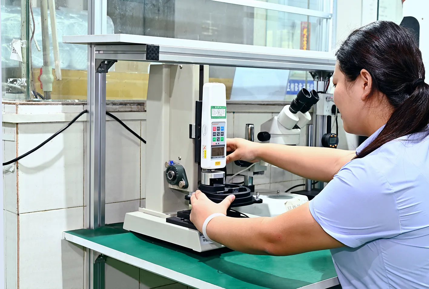
Shrinkage is anisotropic, so compensation is directional. Mold shrinkage runs 1.0-2.0% for the family — roughly double typical ABS values — and flow-direction shrinkage differs from transverse shrinkage by 0.2-0.5% in many TPE grades. Wall thickness shifts the value inside the same part. A cavity compensated as if TPE shrank like ABS produces an undersized, out-of-round part and a steel change order. Compensation is applied per zone and per direction, then confirmed on a trial shot and re-verified on CMM before production.
Compression set picks seal tooling. TPV holds 20-40% set at 70°C for 22 hours; softer SEBS compounds run 40-60% in the same test (typical published values). If the part is a seal, choose the grade by compression set, not hardness — and design the squeeze geometry to the set value, because a seal that takes set loses contact pressure in service.
Polarity drives the overmold architecture. Non-polar SEBS-based TPEs bond well to non-polar PP without primer; polar substrates like ABS, PC, and PA reject unmodified SEBS and need polar-modified grades, TPU, or a TPV adhesion grade. A quick check is the surface-energy delta: below roughly 5 mN/m difference, bonding is achievable without pretreatment; above that, expect weak peel (typical guideline). This single property decides whether your tool is a simple insert mold or a two-shot rotary mold.
Mold Design Considerations for TPE
TPE is forgiving on the machine but demanding on the tool. The rules below are the ones that matter when the steel is being cut for a TPE part — and most of them are different from the rules for rigid plastics.
Shrinkage compensation. Compensate cavities for 1.0-2.0% shrinkage, split by wall-thickness zone and by flow direction. Thick sections shrink more than thin ones, and flow-direction shrinkage exceeds transverse shrinkage by 0.2-0.5% in many grades. On a two-shot mold, the substrate cavity and the TPE cavity are compensated to different numbers — a PP core and a 50A SEBS overmold do not shrink the same way, and the soft layer's final geometry depends on both. The five shrinkage compensation rules apply directly to TPE parts and cover the zone-by-zone, direction-by-direction method.
Ejection design — the TPE difference. A Shore 40A part flexes instead of popping off the core, so pins dimple the surface and small cores hold the part. Draft of 1-3° on soft walls is the starting point (textured surfaces need more), and ejector area must be large — wide pins, blades, or a stripper plate instead of a few small pins. Ejection speed starts slow and is tuned at trial, because a fast, hard eject flexes a soft wall rather than releasing it. The draft angle mistakes list is worth a pass before the steel is cut, since a draft correction after hardening is expensive — and undercuts that would pop free in a rigid part now need lifters or side actions, because the soft wall will not pop.
Two-shot and rotary mold design for overmolding. Overmolding is where TPE earns most of its volume, and the mold architecture is a first-order design decision. Two-shot molds run the substrate shot and the TPE shot in one machine cycle on an index plate or rotary platen; the core stays warm between stations, which is exactly what the bond needs — the substrate surface must sit above the TPE's crystallization temperature at contact (typically 60-90°C at the interface for SEBS compounds) or the TPE skin freezes before chain interdiffusion happens and peel strength collapses. Insert molding is the alternative: the substrate is molded separately, then placed in the TPE cavity, which means preheating or a hot mold is required to reach the same interface temperature. Design the interface thermally in the tool: keep the first-shot core warm, avoid cooling channels that pull the substrate face below the bond window, and never let release agent near the first-shot cavity — contamination is the silent bond killer, and a mold that was never designed to keep the interface warm cannot be fixed in the process.

Substrate matching. The substrate table below is the practical starting map for TPE overmolding. It assumes standard commercial grades, dry clean substrates, and a mold temperature of 40-50°C at the interface. Specialty adhesion grades and primers extend the list, but the map covers 90% of production parts.
| Substrate | TPE grade | Bond mechanism | Typical bond quality | Notes |
|---|---|---|---|---|
| PP | SEBS-based TPE | Non-polar interdiffusion | Strong, cohesive failure | No primer; the reference pair for soft-touch |
| ABS | SEBS or TPU | Polar compatibility | Good with polar-modified grades | Keep ABS dry; mold release kills the bond |
| PA (nylon) | TPV or acid-modified SEBS | Chemical coupling | Moderate to good | Dry substrate, high melt temp, hot mold |
| PC | TPU or SEBS | Polar compatibility | Good | Lower melt temp protects PC from stress cracking |
← swipe to scroll →
Bond quality assumes clean, dry interfaces and a 40-50°C mold temperature. Always verify with a peel test.
Two warnings belong next to this table. POM (acetal) is notoriously hard to overmold: its low surface energy rejects most TPEs without etching or primer. And glass-filled substrates change the surface energy locally, so a grade that bonds to unfilled ABS may delaminate on the glass-filled version. When the substrate is PP, ABS, or PA, the material guides for polypropylene, ABS, and nylon cover the substrate-side properties the bond depends on.
Gate design. TPE accepts edge, fan, submarine, and tab gates; the choice is driven by part size, cosmetics, and where weld lines may land. Gates run larger than a rigid-plastic rule of thumb would suggest — soft melt loses pressure fast through a pin gate, which shows up as short shots and weak weld lines. Gate land stays short, and the gate is placed so flow fronts meet at a vent or a non-cosmetic, non-loaded zone. The gate design best practices guide covers the placement and sizing trade-offs in detail.
Runner system. Cold runners are standard for TPE: full-round runners sized to the part, with generous sprue pullers, because soft sprues stretch instead of snapping. Hot runners work well on high-volume TPE tools — the resin holds its window well — but the flow channels must be free of dead spots where soft melt degrades, and valve gates beat thermal gates where cosmetics matter. The hot runner vs cold runner trade-off follows the same volume and cycle logic as any high-volume tool, with the dead-spot caveat as the TPE difference.
Venting. Soft TPE flows into gaps thinner than 0.02-0.05 mm at the parting line — far tighter than rigid plastics tolerate — so vent depth, seal-off finish, and clamp tonnage matter more than in any rigid material. Worn parting lines flash long before they would on a rigid-plastic mold. Deep, blind pockets may need vacuum venting.
Cooling. Mold temperature is 20-50°C for standard parts, and the cooling layout still decides the cycle — TPE is cooling-limited like any plastic. Keep the cavity and core within a few degrees of each other, and on overmold tools, watch the interface side: cooling that pulls the substrate face below the bond window trades cycle for delamination. The cooling channel design tips cover the layout rules for uniform mold temperature.
Mold steel. Standard TPE tooling runs on P20 or 718-class prehardened steel (28-36 HRC) for most production volumes — the low mold temperature means no exotic hot-side steel. High-gloss and medical parts move to S136 or 420 stainless, hardened and polished. High-cavity, high-volume tools step up to H13 or comparable for core life. On two-shot tools with index plates and moving mechanisms, hardened wear parts on the slides pay for themselves quickly.
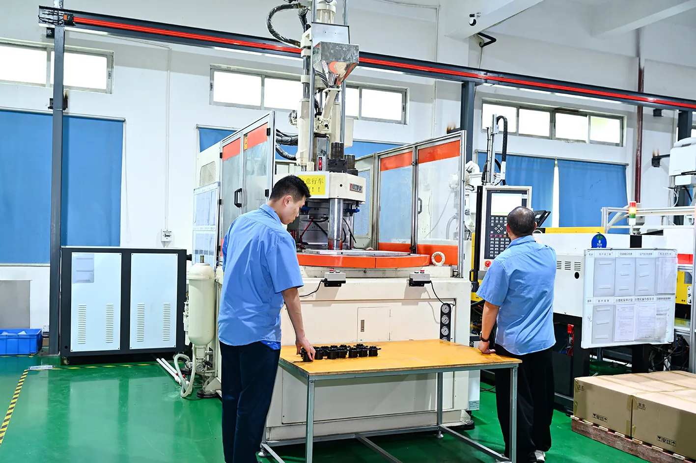
Injection Molding TPE: The Processing Window
TPE barrel temperature runs 170-230°C, with the exact setpoint set by the family and the melt flow rate: SEBS compounds typically process at 180-220°C, TPV runs 190-230°C because the crosslinked rubber domains need more heat to flow, TPU tops the window at 190-230°C, and SBS runs lowest at 160-200°C (typical supplier ranges). The window below is the standard starting point for injection-molding grades; your grade datasheet overrides it.
Drying: family-dependent, often skipped by mistake. SEBS, SBS, TPO, and TPV are non-hygroscopic — a 2-3 hour dry at 60-80°C is a safety habit, not a requirement. TPU is hygroscopic: dry at 80-100°C for 2-4 hours to a moisture content below 0.05%, or splay and bubbles appear in the first shot (typical supplier requirements) — the full TPU processing profile is in the TPU material guide. Because most TPE families do not need drying, splay on a SEBS part points at the process or the tool, not the resin — see the defects section below.
Mold temperature: 20-50°C, higher for bonds. Cool molds speed the cycle, but a mold below 20°C leaves flow marks on glossy surfaces and freezes the bond interface in overmolding. For overmolded soft-touch parts, hold the mold at 40-50°C so the interface stays above the TPE's crystallization temperature long enough to weld. On a two-shot tool, the first-shot cavity and the second-shot cavity may need different mold-temperature zones — the substrate side can run cooler once the part is out, but the bond face must stay warm through the TPE shot.
Pressures and speeds. TPE fills at low injection pressure — typical injection pressure runs 40-80 MPa (400-800 bar) — with fill controlled by speed rather than pressure, because soft melt packs by flow, not by brute force. Transfer to hold pressure early; over-packing a soft cavity creates flash and molded-in stress. Screw speed stays moderate to avoid shear heating, and back pressure is low. On soft grades, cushion control matters: the melt is compressible, and a wandering cushion turns into shot-to-shot weight variation that shows up as flash or short shots at the mold.
Shrinkage: 1.0-2.0%, non-isotropic. The number moves with grade, wall thickness, and process conditions: higher mold temperature and higher hold pressure push shrinkage toward the low end, and flow-direction shrinkage runs above transverse shrinkage. Measure a trial shot, correct the cavity, and re-verify on CMM before production — shrinkage on TPE is confirmed, not assumed.
Cycle time. TPE is cooling-limited like any plastic, but softer grades eject more slowly. Soft walls flex during ejection, so hold time and ejector speed need tuning on the first trial. A 2 mm soft-touch wall typically cools in 15-30 seconds at a 30°C mold temperature (typical range). On two-shot tools, the substrate shot and the TPE shot are optimized together, because the interface temperature of the first shot sets the bond of the second.
Common TPE Applications
Soft-touch grips and overmolded handles carry the largest share of TPE volume — power tool handles, phone cases, and toothbrush grips run 40-70A SEBS over PP or ABS cores on two-shot tools, with the bond window and cavity compensation handled exactly as this guide lays out, following the same logic as our consumer electronics injection molding work. Automotive interiors overmold TPE onto door trim, cup holders, and steering wheel surrounds, while TPV weatherseals and gaskets survive ozone and underhood-adjacent heat — the automotive page covers the tooling requirements behind those programs. Wearable device straps and medical soft-touch parts use SEBS and TPU grades for skin contact and repeated flexing, which our medical device molding practice handles with tighter process control. EV charging handles, cable grommets, and battery-pack seals round out the growth segments — see EV & energy for the sealing and overmolding work in that market.
All of these two-shot and overmolding programs run on tooling built in DieStrike's mold making line, where bond windows, cavity compensation, and gate placement are validated before the tool leaves the floor.
TPE Defects: Mold-Side Root Causes and Fixes
TPE defects divide into three camps: flow defects, bond defects, and ejection defects. Most trace to a mold design decision — temperature, interface cleanliness, or geometry — not a bad shot. The table below maps each common defect to its mold-side root cause and the tooling fix; the process fixes that also work are noted where they matter.
| Defect | Mold-side root cause | Tooling fix |
|---|---|---|
| Flash on soft cores | Low viscosity at thin seal-offs; worn or soft parting line | Repair and harden seal-off steel, raise clamp tonnage; drop melt 10-20°C only as a stopgap |
| Delamination in overmold | Polarity mismatch; cold substrate at the interface; contamination | Match grade to substrate; two-shot tool keeps the core warm between stations; design the interface at 40-50°C; ban release agents; add mechanical interlock geometry |
| Short shot | Undersized or restricted gate; imbalanced runner; hot-runner dead spots | Enlarge the gate, balance the runner, purge dead spots; raise melt 5-10°C and increase injection speed as process checks |
| Sink marks | 1.0-2.0% shrinkage unsupported by packing; thick sections behind surfaces | Rib thick sections at 50-60% of wall, size the gate so packing reaches the thick zone before freeze-off, extend hold time |
| Weld lines | Converging flow fronts freeze before knitting | Move the gate so fronts meet at a vent or non-cosmetic zone, add venting at the meeting line, raise mold temperature |
| Splay and bubbles | Moisture in TPU; shear heating from high screw speed; long hot-runner residence | Dry TPU to below 0.05% moisture, cut screw speed 20-30%, check residence time in the manifold |
| Sticking and ejection marks | Soft TPE wraps cores; insufficient draft; undersized ejector area | Add 1-3° draft, enlarge ejector area with blades or a stripper plate, slow the initial ejection speed |
← swipe to scroll →
First fixes are process-side. Persistent defects usually require mold-side changes.
Flash deserves special attention. Soft TPE flows into gaps thinner than 0.02-0.05 mm at the parting line, so seal-off surface finish and clamp tonnage matter more than in rigid plastics. A TPE mold with worn parting lines flashes long before a rigid-plastic mold would, and the fix is a steel repair, not a process tweak. Specify hardened seal-offs on high-cavity TPE tools and check parting-line wear in preventive maintenance.
Ejection is the most underestimated risk. A Shore 40A part flexes instead of popping off the core, so ejector pins dimple the surface and small cores hold the part. Draft of 1-3° on soft walls, larger ejector areas, and slower initial ejection speed prevent most of the damage. If the part survives ejection, verify geometry on CMM before the mold leaves the trial phase — a flexed part that looks right may be out of spec against the 1.0-2.0% shrinkage budget.
Delamination is a bond-interface failure, and it is mostly decided in the tool. Polarity mismatch is a grade-selection error; a cold substrate surface is a mold-design error — two-shot tools keep the core warm between stations by design, while insert molds need preheating or a hot mold. Mechanical interlocking is a legitimate backup, not a substitute for chemistry: undercuts, ribs, and roughened surfaces add 30-100% peel resistance on marginal bonds (typical results), and a chemically bonded interface fails cohesively inside the TPE while a mechanically held one fails at the interface. Design the bond chemically, and let geometry add margin. For the systematic version of this workflow — including how to isolate a bond failure from a flow failure — run the DFM checklist against the part before the steel is cut, and re-run it on the trial shots.

TPE vs LSR: Comparison Table
TPE and liquid silicone rubber (LSR) compete in the same soft-part applications, but they are different materials with different tooling economics. TPE is a thermoplastic: it melts, molds, and remelts, with a Shore 5A-60D range and heat resistance around 100-135°C. LSR is a thermoset silicone that cures by platinum catalysis inside a hot mold, with continuous service to 200-250°C and no melting at all. The table below uses typical published values; actual numbers vary by grade.
| Criterion | TPE | LSR |
|---|---|---|
| Polymer class | Thermoplastic, physically crosslinked | Thermoset silicone, platinum-cured |
| Recyclable | Yes, regrind at 10-20% ratios | No; cured scrap is waste |
| Hardness range | Shore 5A-60D | Shore 10-80A |
| Continuous heat resistance | ~100-135°C by family | ~200-250°C |
| Low-temperature service | ~-40°C typical | ~-60°C typical |
| Cycle time | 20-60 s, no cure step | 60-180 s, cure-limited |
| Mold temperature | 20-50°C | 120-180°C |
| Tooling system | Standard injection mold | Cold-deck hot runner, cooled barrel |
| Material cost | ~$2-6 per kg typical | ~$15-30 per kg typical |
| Biocompatibility | Medical grades available | ISO 10993 standard for LSR |
← swipe to scroll →
Cost figures are typical market ranges for standard grades. Specialty medical and flame-retardant compounds run higher.
Do not swap one for the other without re-engineering the tool. A TPE mold runs at 20-50°C with a standard injection mold and a conventional runner. An LSR mold runs at 120-180°C with a cooled injection unit and a cold-deck manifold — the mold design, the steel, and the press specification are different. The choice usually collapses to temperature, cycle time, and cost: TPE wins on cycle time and price per kilogram; LSR wins on heat resistance, long-term sealing, and biocompatibility, which is why baby bottle nipples and implant-adjacent parts stay with silicone. If the part sees sustained heat above 135°C or demands long-term sealing against fluids, LSR is the honest answer — the complete processing profile is in the liquid silicone rubber material guide. For everything else, TPE delivers the same softness at a fraction of the cycle time and material cost.
Frequently Asked Questions
Q1. What is thermoplastic elastomer (TPE)?
A thermoplastic elastomer is a polymer with rubber-like elasticity and thermoplastic melt processing. Physical crosslinks from hard block domains provide the elasticity. Heat dissolves them so the material flows and can be remolded. The main families are SEBS, SBS, TPO, TPV, and TPU — and the family choice drives the mold decisions in this guide.
Q2. TPE vs silicone: what is the difference?
TPE is a thermoplastic that melts, molds, and recycles. Silicone, including LSR, is a thermoset that cures and cannot be remelted. TPE handles 100-135°C continuous service, while LSR handles 200-250°C. TPE cycles in 20-60 seconds; LSR takes 60-180 seconds because of the cure step. The tooling is different too: TPE runs on a standard 20-50°C mold, LSR on a 120-180°C cold-deck system.
Q3. Is TPE recyclable?
Yes. TPE scrap, runners, and sprues are reground and reprocessed at 10-20% regrind ratios in most standard grades. The physical crosslinks reform after each melt cycle. This recyclability is the core difference between TPE and thermoset rubber, which cures once and cannot be reprocessed.
Q4. What Shore hardness range does TPE cover?
TPE spans Shore 5A to 60D across its families. SEBS covers 5A-95A, SBS covers 30A-90A, TPO covers 50A-60D, TPV covers 40A-50D, and TPU extends from 60A to 75D. Hardness is measured with a durometer under ASTM D2240 or ISO 868, and the test method and temperature belong on the spec — because hardness sets the draft, ejector area, and ejection speed the mold is built with.
Q5. What temperature do you injection mold TPE at?
Barrel temperature runs 170-230°C depending on family: SEBS at 180-220°C, TPV and TPU at 190-230°C, SBS lowest at 160-200°C. Mold temperature is 20-50°C for standard parts and 40-50°C for overmolding, to keep the bond interface warm. TPU must be dried to below 0.05% moisture before molding.
Q6. Does TPE bond to PP, ABS, and PA in overmolding?
Yes, with the right grade pairing. SEBS-based TPE bonds strongly to PP without primer. ABS needs polar-modified SEBS or TPU. PA needs TPV or acid-modified SEBS, a dry substrate, and a hot mold. Bond quality is verified with a peel test, and contamination plus a cold interface are the top causes of delamination.
Q7. What is the TPE shrinkage rate?
Mold shrinkage for TPE is 1.0-2.0%, varying with grade, wall thickness, and process conditions, and it is not isotropic — flow-direction shrinkage differs from transverse shrinkage by 0.2-0.5% in many grades. Cavities are compensated per zone and per direction, then tuned on the first molding trial and re-verified on CMM.
Q8. How is TPE overmolded — two-shot or insert molding?
Two-shot molding runs the substrate and the TPE in one cycle on an index-plate or rotary-platen mold, keeping the core warm between stations so the interface stays above the TPE's crystallization temperature. Insert molding molds the substrate separately and places it in the TPE cavity, which needs preheating or a hot mold to reach the same interface temperature. Two-shot wins on bond quality and cycle; insert wins on tooling simplicity — the interface temperature requirement decides which one your part needs.
The Bottom Line
TPE succeeds on four mold-side conditions. The family matches the thermal duty, and the shrinkage behavior is compensated per zone and per direction. The hardness spec carries a test condition, and the ejection system is designed for a part that flexes instead of popping. The overmold interface is engineered for polarity and temperature — in the tool, not at the trial. And the parting line, gates, and vents are cut for a material that flashes where rigid plastics would not.
It fails four ways too. A cold mold freezes the bond. A contaminated substrate blocks diffusion. A Shore D application gets filled with a Shore A grade. And a cavity compensated like a rigid plastic produces an undersized soft part. Every one of those failures is visible on the drawing long before the steel is cut.
DieStrike builds TPE and overmolding molds to IATF 16949 / ISO 9001 systems. Cavity dimensions are verified to ±0.005 mm on CMM, and DFM feedback lands within 24 hours. Send the part drawing with the soft-touch requirement and the operating temperature, and the design review covers family selection, shrinkage compensation, and the overmold bond window before steel is cut — the same review discipline described in how to buy injection molds.
KEEP READING
Related Reading
ABS Injection Molding: The Complete Material Guide
ABS injection molding for buyers and mold engineers: shrinkage 0.4-0.
Read articleArticleEjector Pin Steel: SKD61 vs H13 — What's the Difference?
SKD61 (JIS) and H13 (AISI) are two names for the same 5% chromium hot-work steel; ejector pins in both grades harden to…
Read articleArticleLiquid Silicone Rubber (LSR) Injection Molding Guide
Liquid silicone rubber (LSR) is a two-component platinum-cured thermoset with -50°C to +250°C service life.
Read articleArticleNylon (PA) Injection Molding: Grades, Properties & Processing
Nylon (PA) injection molding guide: PA6, PA66, PA12, PA46 and glass-filled grades compared — melting points, shrinkage…
Read articleNEXT STEP
Ready to Start Your Mold?
Send us your element dimensions or part numbers — our team responds within 24 hours with pricing and lead time.

Written by
Ray ChanMold Buyer's Guide Author · Precision Mold Manufacturing Specialist. Ray helps global importers, distributors and OEMs source factory-direct molds and mold parts.