
PET Injection Molding: Crystallization, Drying and Material Guide
Table of Contents
A mold shop quotes a 32-cavity PET closure tool assuming PBT-style cycle times, ships it, and the parts come out hazy, brittle and out of dimension. The root cause is rarely the press settings. It is a mold designed without understanding that PET crystallizes 10 to 20 times slower than PBT, holds 0.02% moisture as a hard ceiling, and splits into two completely different materials depending on mold temperature. Each of those facts changes steel choice, cooling layout, gate design and cycle time. Get one wrong and you cut the error into the tool before the first shot.
This guide is written from the mold-making side. Processing numbers appear only where they change a tooling decision. The target reader is a buyer or engineer specifying an injection mold for PET, whether that is a preform cavity set, an electrical connector housing or a transparent packaging component.
The Snapshot
- PET crystallization half-time is measured in minutes near 180°C, while PBT crystallizes in seconds. Mold temperature, not resin, sets the final structure.
- Drying: desiccant dryer at -40°C dew point, 150-165°C resin temperature, 4-6 hours, moisture below 0.02% typical ceiling. Preform work often targets 0.005%.
- Melt temperature window is 260-290°C typical. Above 290°C the resin generates acetaldehyde and drops intrinsic viscosity fast.
- Mold temperature splits the process: 10-30°C yields clear amorphous APET, 120-140°C yields opaque crystalline CPET. The mold must be built for one play or the other.
- Shrinkage spans roughly 0.5-0.7% for amorphous PET up to 1.2-2.0% for crystalline grades, and 0.3-0.9% for glass-filled grades. These are typical industry figures and they must be confirmed before steel is cut.
PET vs PBT: Crystallization Speed Changes the Mold
PET and PBT are both polyester family members, and buyers often assume a PBT mold design transfers to PET. It does not. The decisive difference is crystallization kinetics. PBT crystallizes so fast that it solidifies at mold temperatures of 60-90°C and still ejects fully crystalline parts. PET crystallizes at a snail's pace by comparison. Its peak crystallization rate sits near 170-190°C, and even there the half-time is minutes, not seconds.
That slow rate creates two opposite engineering consequences, and both land on the mold. First, if you quench PET against a cold cavity at 10-30°C, the chains freeze before they can organize. You get amorphous, transparent APET with low shrinkage near 0.5-0.7%. Second, if you want crystalline CPET for heat resistance up to roughly 220°C short-term, you must hold the cavity at 120-140°C long enough for crystallization to finish. Cycle time roughly doubles or triples versus a cold-cavity run. Cooling channel layout and cycle cost are therefore decided by which PET structure the part needs.
For mold designers, PBT is the forgiving cousin. PET is the material that punishes sloppy thermal design. A tool built for CPET needs mold-heating channels that hold 130°C within ±3°C across the cavity, plus insulation boards and heat-resistant seals. A tool built for APET needs fast, turbulent cooling at 10-30°C and a polish that keeps the amorphous surface optical-clear.
| Parameter | PET (typical) | PBT (typical) | Mold-side implication |
|---|---|---|---|
| Crystallization half-time near peak rate | Minutes | Seconds | PET structure is set by mold temperature, not just chemistry |
| Drying, -40°C dew point | 150-165°C, 4-6 h, below 0.02% | 120-140°C, 3-4 h, below 0.02% | Hotter, longer drying raises shop energy load but not tool design |
| Melt window | 260-290°C | 230-260°C | PET hot runners need higher-temp heaters and thermocouple accuracy of ±2°C |
| Mold temperature | 10-30°C (APET) or 120-140°C (CPET) | 60-90°C | CPET tools need heating channels, insulation boards and hot-work seals |
| Unfilled shrinkage | 0.5-0.7% amorphous, 1.2-2.0% crystalline | 0.9-2.0% | PET shrinkage is a design variable you choose, then cut into the steel |
| Glass-filled shrinkage | 0.3-0.9%, strongly anisotropic | 0.3-0.9%, strongly anisotropic | Gate location controls fiber orientation and final dimensions |
← swipe to scroll →
Table note: All values are typical industry processing figures for molding-grade resins and vary by grade and supplier. Confirm against your resin datasheet before cutting steel.
One more difference matters for tool life. PET melt is less aggressive toward steel than flame-retardant or filled grades, but CPET processing keeps cavities at 130°C continuously, so thermal fatigue and corrosion-resistant steel selection become the governing factors. Our PBT material guide covers the mirror-image case where fast crystallization dominates the tooling decisions.
APET vs CPET: Two Materials From One Resin
APET means amorphous PET. It is the clear, glassy structure you get when molten PET is quenched below roughly 70°C, its glass transition zone, before crystals can form. Transparency comes from the absence of crystalline domains that scatter light. Shrinkage stays low, typically 0.5-0.7%, and dimensional behavior is predictable because there is no crystallization to vary with local cooling rates.
CPET means crystalline PET. Hold the mold at 120-140°C and the chains fold into spherulites. The part turns opaque and whitish, chemical resistance improves, and heat deflection jumps. Crystalline PET parts survive short exposures near 220°C, which is why CPET trays go into ons. Shrinkage rises to roughly 1.2-2.0% and, critically, it becomes dependent on how completely crystallization finished in each section of the part.
For a mold maker, these are effectively two different tooling programs. An APET tool is a high-speed, cold-cavity, optical-finish mold. It needs cavity polish in the SPI A range or better, chilled water at 10-20°C, and tight cavity temperature uniformity of ±3°C so haze does not vary shot to shot. A CPET tool is a heated mold with hot-work considerations, longer cycles of 40-90 s typical, and shrinkage compensation that accounts for variable crystallinity across thick and thin sections.
Never build one tool and promise the buyer both structures. The cooling circuit geometry for a 20°C cold tool directly conflicts with the heating circuit needs of a 130°C hot tool. If a program may switch, say from clear to heat-resistant parts, the mold design must reserve space for heating cartridges or a conformal channel set, and that decision has to happen at DFM stage, not after steel is ordered.
Drying PET: -40°C Dew Point, 4-6 Hours, 0.02% Ceiling
PET is hygroscopic. It absorbs water into the polymer bulk, and at 260-290°C melt temperature that water drives hydrolysis, chopping molecular chains. The visible results are splay marks, silver streaks and a drop in intrinsic viscosity, IV, the number that defines PET strength. Bottle-grade PET typically ships at IV 0.72-0.84 dL/g, and every 0.02 dL/g of IV loss weakens blow-molded bottles and molded parts measurably.
The industry-standard drying recipe is a desiccant dryer holding a -40°C dew point, resin at 150-165°C, for 4-6 hours, to reach moisture below 0.02%, which is the typical ceiling for general molding. Preform and high-clarity work often targets 0.005% or lower. Hot-air dryers cannot reach these levels, because a -40°C dew point requires desiccant, and any mold buyer auditing a supplier should ask which dryer type feeds the PET press.

Drying is a process issue, but it changes mold behavior in two ways. First, under-dried PET generates gas at the gate, so venting capacity becomes critical, which we cover below. Second, dried PET must be protected between dryer and press. A closed-loop loading system with a dryer-mounted hopper keeps moisture from rebounding during a 20-minute transfer, because regrind-free bottle-grade PET reabsorbs measurably within 30 minutes of open-air exposure at typical shop humidity of 50% RH.
If your parts show silver streaks, fix the material side first, then audit the mold. Our guide on splay and silver streaks separates wet-resin symptoms from venting and shear symptoms, and it applies directly to PET.
Melt Temperature Window: 260-290°C and Its Limits
Injection-molding-grade PET processes in a melt window of roughly 260-290°C typical. Below 260°C the melt viscosity climbs and filling gets sluggish, which forces higher injection pressure and more shear heating at the gate. Above 290°C two degradation mechanisms kick in. The resin produces acetaldehyde, AA, the compound that gives bottled water a sweet off-taste, and IV drops through thermal and hydrolytic chain scission.
Acetaldehyde generation is the reason preform molds obsess over melt control. Bottlers specify AA levels in the finished bottle, often below 1-3 ppm typical, and preform tools minimize residence time to hold that spec. For a mold designer this means: no dead zones in the runner system, balanced hot-runner manifolds with residence time measured in seconds, and thermocouples holding ±2°C on every nozzle.
The melt window also sets hot-runner hardware requirements. PET-grade hot runners run nozzles at 275-290°C continuously, so heater bands, nozzle bodies and manifold seals must be rated well above 300°C. A runner system spec'd for a 240°C material like PBT will drift and degrade when forced to PET temperatures. When quoting a PET tool, we state heater watt density and thermocouple placement per nozzle, because a 5°C hot spot in one cavity of a 32-cavity set produces measurable IV variation between parts.
Shear heating adds to barrel set temperature. Fast injection through an undersized gate can raise local melt temperature by 10-20°C above the set point, enough to trigger AA formation and burn marks at the gate. Gate sizing is therefore not just a filling question. It is a material-integrity question for PET.
Mold Temperature: The Amorphous and Crystalline Plays
Mold temperature is the single most consequential variable in PET tooling, because it selects the material structure, as covered in the APET vs CPET section. The two plays demand opposite thermal systems built into the same mold frame.
The cold play, APET. Cavity at 10-30°C, chilled water at 8-15°C supply. The mold must remove heat fast and evenly. Channel-to-cavity distance of 15-25 mm typical, turbulent flow with Reynolds number above 4000 to keep the heat-transfer coefficient high, and channel uniformity within ±3°C cavity-to-cavity. Warm spots above 70°C let surface crystallization start, and the part hazes. A cold play is a cooling-engineering job: baffles, bubblers or conformal channels near thick sections, and a polish that survives condensation management since chilled molds sweat at high shop humidity.
The hot play, CPET. Cavity at 120-140°C held by pressurized hot water, oil or cartridge heaters. Now the mold engineering flips: the frame needs insulation boards between mold plates and press platens to cut conductive loss, heat-resistant O-rings rated above 160°C, and ejector pins with extra clearance because everything at 130°C grows thermally. A 500 mm mold plate of P20 steel expands roughly 0.6 mm when heated from 20°C to 130°C, at about 12 µm/m/°C. Fit tolerances on slides and lifters must absorb that growth or the mold galls within days.
Cycle time is where the money lives. An APET cold tool can run cycles of 8-20 s typical for small parts. A CPET tool runs 40-90 s typical because crystallization time is chemistry, and no pressure shortcut exists. Buyers comparing quotes across the two plays must compare cost per thousand parts, not mold price. If you are still deciding which polyester fits the program, our overview on how to choose a plastic material walks the trade-off tree.
Shrinkage and Warpage: Anisotropy You Must Cut Into Steel
PET shrinkage is not one number. It is a family of numbers that depend on structure, fill and flow direction, and every one of them gets cut into cavity dimensions before the first shot. Typical industry figures: amorphous APET shrinks 0.5-0.7%. Crystalline CPET shrinks 1.2-2.0% because crystal packing pulls chains closer. Glass-filled grades shrink 0.3-0.9% overall but show the sharpest anisotropy of all.
Anisotropy means shrinkage differs between flow direction and transverse direction. In a 30% glass-filled PET part, flow-direction shrinkage can run 0.3% while transverse shrinkage hits 0.8%, a ratio near 2.5:1. Fibers align with flow and resist shrinkage along their length. The mold designer cannot average these numbers. Flatness on a 100 mm span can vary by 0.5 mm or more purely from gate placement driving fiber orientation.
Three mold-side levers control the outcome. First, shrinkage factor selection: cut cavities at the confirmed datasheet factor for the exact grade and structure, with T1 samples scheduled to measure and correct. Second, gate location and count: gates decide flow length and orientation patterns, so a warpage problem is often a gate-location problem wearing a process disguise. Third, uniform cooling: a cavity 15°C hotter on one side shrinks differently on that side, and the part bows toward the hotter face.
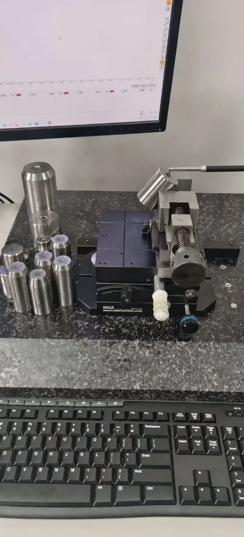
For dimensional programs holding ±0.05 mm on critical features, we run mold-flow analysis before steel is cut to predict the orientation map, then hold cavity machining to ±0.005 mm on the mold and ±0.002 mm on critical mold components. Correction happens in the tool at T1 and T2 sampling, not by chasing press settings for six months.
Gates and Runners for PET
PET's melt strength and fast freezing make gate design unforgiving. PET solidifies quickly against cold steel, so gates must be sized to fill fast without shear-induced degradation. The working rule: enough cross-section to avoid premature freeze, balanced against shear heating that locally pushes melt above the 290°C ceiling.
Gate types that work. Valve gates on hot runners are the standard for preform and packaging work, because they cut the flow path cleanly and leave no gate stress that cracks clear APET parts. Edge gates and submarine gates work for crystalline CPET where cosmetics matter less. Pin-point gates on cold runners are usable only for small parts, since PET's fast freeze chokes undersized gates and short shots follow.
Gate sizing numbers. For a hot-runner valve gate feeding packaging-grade PET, gate diameters of 1.5-3.0 mm are typical depending on wall thickness and shot volume. Cold-runner edge gates run 50-75% of wall thickness. These are starting points, not guarantees. Every program confirms sizing with mold-flow fill analysis before we cut cavity steel.
Runner decisions. At production volumes above roughly 500,000 parts, hot runners usually win on PET because the regrind problem is real. Cold-runner PET regrind is often downgraded or excluded from clear and food-contact work, so a cold runner converts 5-15% of shot weight into scrap on small-part tools. Preform molds take this to the extreme: every gram of runner is lost money at millions of cycles.

Gate vestige also drives structure choice. Clear APET parts show gate blush and stress whitening at undersized gates, while CPET parts tolerate smaller gates because opacity hides cosmetics. If the program needs both structures over its life, gate design must satisfy the stricter APET case.
Venting and Steel Selection for PET Molds
PET vents two kinds of gas. Under-dried resin releases steam and hydrolysis byproducts at the flow front. Even dry PET releases air that the melt traps in ribs, bosses and weld-line zones. Burn marks and short fills on PET tools trace back to vent starvation more often than to press settings, because PET fills fast and the trapped gas compresses adiabatically, spiking locally to several hundred degrees.
Venting numbers. For unfilled PET, vent depths of 0.02-0.03 mm at the parting line are typical, machined to ±0.005 mm. Glass-filled PET needs shallower vents, roughly 0.015-0.025 mm, because fibers bridge the vent and glass dust packs into the channel over thousands of shots. Vents must be reachable for cleaning: every 50,000-100,000 shots a PET tool's vents need degreasing, and designs that bury vents under lifters with no access window guarantee defect drift.
Steel selection follows structure. For clear APET tools, cavity steels must polish to optical finish and resist corrosion from chilled-water condensation. Stainless mold steels like S136-class hardened to HRC 48-52 typical, or through-hardened corrosion-resistant grades, hold a SPI A polish and survive condensation cycles. For CPET tools at 130°C, thermal fatigue and temper stability govern: steels must keep hardness at temperature, and cavity surfaces see continuous thermal cycling. Pre-hardened P20 works for prototype and low-volume PET molds at HRC 28-32, but production volumes push toward hardened and polished stainless.
DieStrike holds cavity heat treatment to HRC 62 on wear-critical components and machines mold cavities to ±0.005 mm, with mold component geometry at ±0.002 mm. On a 96-cavity preform mold, that component-level accuracy is what keeps cavity-to-cavity preform weight variation within bottler spec. Vent depths, gate diameters and polish grades are all documented in the mold's inspection report before shipment.
Failure Modes: How PET Molds Actually Fail
1. Haze drift on APET tools. Symptom: clarity drops over weeks. Cause chain: cooling channel scale builds up, cavity temperature creeps from 20°C toward 45°C, surface crystallization starts. Fix: scheduled channel cleaning and flow monitoring. This is a maintenance-program failure, not a design failure, and it is preventable with documented cooling specs.
2. Gate freeze and short shots. Symptom: incomplete fill at fast cycles. Cause: gate sized for PBT freeze behavior, not PET's faster solidification at cold-cavity temperatures. Fix: enlarge valve gate or raise nozzle temperature within the 290°C ceiling. The mold-side diagnosis order for incomplete fill is gate size, vent capacity, then fill speed, in that sequence.
3. Brittle parts with low IV. Symptom: parts crack at ejection or in drop tests, intrinsic viscosity reads 0.68 dL/g against a 0.80 spec. Cause: wet resin, overheated melt or long residence time in an unbalanced manifold. The mold-side contributor is runner design: oversized cold manifolds hold melt for minutes and cook it.
4. Warpage from uneven crystallinity. Symptom: CPET parts bow 0.3-0.8 mm across a 100 mm span. Cause: one cavity face runs 15°C hotter, crystallizes more, shrinks more. Fix: cavity temperature uniformity verification at T1 with a thermal camera or embedded sensors, then channel correction in steel.
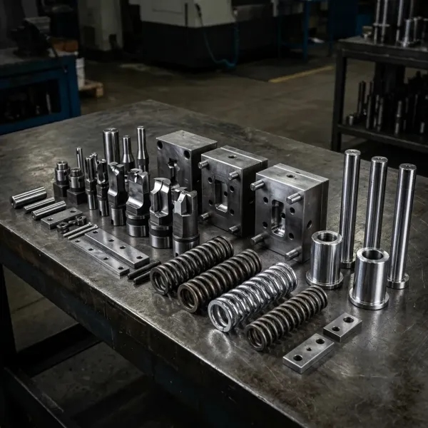
5. Vent packing on glass-filled PET. Symptom: burn marks appear at 300,000 shots, not at T1. Cause: glass dust and degradation residue compacting into vents. Fix: shallower vents, easier vent access, and cleaning intervals written into the maintenance schedule at 50,000-shot steps.
6. Ejector pin wear on hot CPET tools. Symptom: pin marks deepen, pins gall in their bores. Cause: 130°C operation softens the part, and thermal growth tightens clearances designed for cold operation. Fix: pins and sleeves specified with temperature-compensated fits, plus nitrided or coated pin surfaces.
Five of these six modes are decided at design stage. That is the argument for DFM review on every PET tool before steel is ordered, and it is why we return DFM feedback within 24 hours of receiving a drawing.
Applications: Preform Molds and Electrical Parts
Preform molds. The highest-volume PET injection application on earth. A preform is the test-tube-shaped precursor to a PET bottle, molded in APET form, then reheated and stretch-blow-molded. Preform tools are the extreme sport of PET mold making: 24, 48, 72 or 96 cavities typical, valve-gated hot runners, post-mold cooling, and cycle targets of 8-12 s. Cavity weight variation across the mold directly becomes bottle wall-thickness variation, so component machining at ±0.002 mm and balanced manifolds holding ±2°C per nozzle are the entry ticket. AA generation must stay low enough for food contact, which caps residence time and melt temperature.
Electrical and connector parts. Glass-filled PET, typically 30% glass, competes with PBT in connectors, bobbins, sensor housings and switch components because it holds stiffness at high temperature and resists soldering heat. The mold-side realities: strong anisotropy, so gate location drives flatness; abrasive melt, so wear plates, hardened slides and HRC 58+ surfaces at fiber contact points; and tight vent depths of 0.015-0.025 mm to keep glass from packing. Connector OEMs including TE Connectivity, Amphenol and Luxshare demand cavity-to-cavity consistency across multi-cavity sets, which is a machining-precision and thermal-balance problem long before it is a process problem.

CPET trays and technical parts. Oven-safe food trays, appliance housings and heat-exposed automotive secondary components use the crystalline play. The 120-140°C mold temperature, 40-90 s cycles and heated-tool engineering described earlier all apply. Programs quoting CPET parts must carry the cycle-time cost honestly, because a CPET part costs 3-5 times more in press time than the same part in APET, at typical shop rates.
PET Mold Design Checklist
Before releasing a PET mold design, we run this checklist. Buyers can use it to audit any supplier's proposal.
- Structure declared: APET or CPET, with shrinkage factor written on the cavity drawing, not assumed. Our rules for shrinkage compensation in mold design apply with the structure-specific factor.
- Drying verified in the quote review: -40°C dew point desiccant dryer, 4-6 h, moisture below 0.02% typical ceiling.
- Melt path rated 290°C+ with ±2°C thermocouple control per nozzle, and residence time computed for the manifold.
- Thermal system matched to structure: 8-15°C chilled loop with turbulent flow for APET, or 130°C heating loop with insulation boards and high-temp seals for CPET.
- Vent depths set at 0.02-0.03 mm unfilled or 0.015-0.025 mm glass-filled, with access for cleaning every 50,000-100,000 shots.
- Steel selected for the play: polishable stainless for clear APET, temper-stable and hardened for CPET hot tools, hardened wear surfaces for glass-filled grades.
- Thermal growth fits calculated for hot tools, roughly 12 µm/m/°C, on slides, lifters and ejector bores.
- T1 sampling plan includes cavity temperature mapping and IV or weight checks, not just dimensional reports.
A final note on verification. PET programs live or die on first-article data. At T1 we record cavity temperatures at minimum 4 points per cavity family, part weight per cavity to ±0.01 g, and dimensional results against the declared shrinkage factor. That record, not a verbal "parts look good", is what separates a tool that ramps in two trials from one that cycles through five.
FAQ
Q1. What is the difference between PET and PBT for injection molding?
Both are polyesters, but PBT crystallizes in seconds at mold temperatures of 60-90°C while PET needs minutes near its 170-190°C peak rate. PET therefore splits into amorphous APET at 10-30°C mold temperature or crystalline CPET at 120-140°C. PET also runs hotter, with a melt window of 260-290°C versus 230-260°C for PBT, and dries hotter at 150-165°C for 4-6 hours.
Q2. How dry must PET be before molding?
Below 0.02% moisture is the typical ceiling for general molding, and preform or high-clarity work often targets 0.005% or lower. Use a desiccant dryer at -40°C dew point with resin at 150-165°C for 4-6 hours. Wet PET hydrolyzes at melt temperature, dropping intrinsic viscosity and showing up as splay, silver streaks and brittle parts.
Q3. Why is my PET part hazy or not transparent?
Transparency requires the amorphous structure, which needs quenching below roughly 70°C before crystals form. Haze means some cavity region ran above 70°C, often from cooling channel scale, unbalanced flow or a thick section retaining heat. Check cavity temperature uniformity first: clear APET tools should hold 10-30°C within ±3°C across all cavities.
Q4. What shrinkage factor should a PET mold be cut at?
Typical industry figures: 0.5-0.7% for amorphous APET, 1.2-2.0% for crystalline CPET, and 0.3-0.9% for glass-filled grades with strong flow-direction anisotropy. The exact grade datasheet value governs, and T1 samples must verify it before any cavity correction is cut. Never quote a PET tool with a single generic shrinkage number.
Q5. Can one mold produce both APET and CPET parts?
Not practically. The two structures need opposite thermal systems: chilled water at 8-15°C supply for APET versus 120-140°C heated circuits for CPET, plus insulation boards and high-temperature seals that a cold tool does not carry. The shrinkage factors also differ by roughly 2-3 times, so cavity dimensions cannot serve both. Decide the structure at DFM stage.
The Bottom Line
PET is a material that turns mold design decisions into part quality. Structure, drying, vent depths and thermal balance must all be locked in steel before the first shot. DieStrike builds PET tooling at ±0.005 mm mold precision and ±0.002 mm component geometry, with DFM feedback in 24 hours and injection mold lead times of 2-5 weeks. If your program involves PET, preform or glass-filled electrical parts, you can start with a drawing review through our contact page.
KEEP READING
Related Reading
PBT Material Guide
PBT crystallizes in seconds where PET needs minutes, and that gap drives drying, mold temperature and cycle time decisions.
Read articleArticleHow to Fix Splay and Silver Streaks
Wet PET shows up as splay and silver streaks first, so this troubleshooting guide pairs directly with the drying section here.
Read articleArticleHow to Prevent Sink Marks: 8 Mold-Side Root Causes
Gate sizing and packing access decide whether PET parts sink, and these eight mold-side fixes apply to crystalline PET especially.
Read articleArticleLCP Material Guide
LCP is the extreme case of anisotropic shrinkage, useful for comparing against the flow-direction behavior of filled PET.
Read articleNEXT STEP
Ready to Start Your Mold?
Send us your element dimensions or part numbers — our team responds within 24 hours with pricing and lead time.

Written by
Ray ChanMold Buyer's Guide Author · Precision Mold Manufacturing Specialist. Ray helps global importers, distributors and OEMs source factory-direct molds and mold parts.