
How to Prevent Sink Marks: 8 Mold-Design Root Causes and Fixes
Table of Contents
A gloss appliance housing was scrapped at final inspection because 0.05 mm dimples sat above two internal screw bosses. The dimples were sink marks: the skin over each boss had been pulled inward while the thicker material underneath cooled and shrank. The part measured in spec, hit its target weight, and passed every dimension. It failed on looks, and the customer returned the entire lot.
A sink mark is a shallow surface depression, usually opposite a rib, boss, gusset, or other locally thick section. The visible surface solidifies against the cavity steel first. The mass underneath stays molten longer, shrinks as it cools, and drags the thin skin inward before it gains enough stiffness to resist. The result is a cosmetic dish that no dimensional tolerance catches.
This article goes deep on sink marks only. Our nine-defect troubleshooting guide covers flash, short shots, weld lines, and the rest; this one stays on the single defect and its mold-side causes. It is written for mold buyers, part designers, and tooling engineers who approve geometry at the DFM stage and specify the tool that follows. Process levers appear only where a mold dimension decides whether they can work. Data values are typical published or industry practice; verify against your grade datasheet and mold maker before cutting steel.
The Snapshot
- Sink marks form where a rib, boss, or gusset thickens the local section, so the shrinking core pulls the skin inward.
- Keep rib bases at 0.5 to 0.6x nominal wall, boss walls near 0.6x, and wall transitions under 2 to 1.
- Gate near the sink-critical feature with a depth of 50 to 80% of wall so packing reaches it before freeze-off.
- Run cooling channels 2 to 2.5x their diameter from the cavity surface, including under bosses.
- Beryllium copper inserts move heat at 105 to 130 W/m·K versus tool steel at 25 to 30 W/m·K.
- Sinks read on gloss surfaces from roughly 0.025 mm up, so set that as a trial acceptance value.
What a Sink Mark Is: Surface Dip vs. Internal Void
Injection molding freezes plastic from the outside in. The skin touching the cavity steel cools first and hardens. The center of a thick section cools last, and every polymer shrinks as it loses heat. When the shrinking core cannot draw enough melt through the still-open gate, it pulls on the skin above it. A thin, unsupported skin dips inward, and that dip is the sink mark.
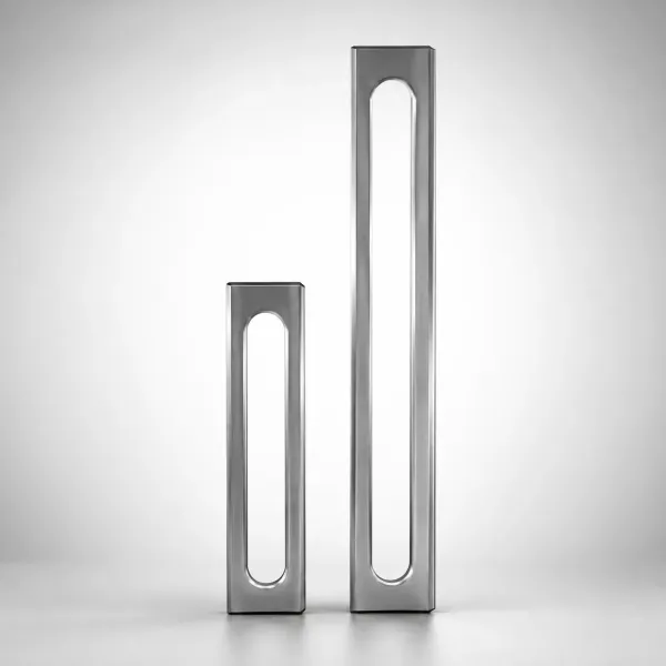
Sink depth on typical parts runs from a barely visible 0.01 mm up to 0.2 mm on high-shrink resins with heavy local sections. Depth tracks three things: how much the material shrinks, how thick the local section is, and how long the skin stays soft enough to be pulled. All three are locked before the press ever runs.
Sink marks and voids are cousins with the same parent cause: a thick section that cannot be packed. A void is an internal cavity left inside the part, invisible from the surface. A sink mark is the surface version, formed when the skin yields to the pull of the shrinking core. Which one appears depends on skin stiffness and cooling balance.
A thick, well-cooled skin on the visible face resists the pull, so the center tears open into a void instead. A thin or warm skin gives way, and the surface dips. Mold cooling layout and steel choice decide which side of the part yields, which is why this is a mold-design problem before it is a process problem.
Voids hide inside the wall and show up only on sectioned parts, x-ray checks, or weight loss. Sink marks show up on the surface under normal light. A tool that fixes one often trades it for the other: aggressive cavity-side cooling can move the defect inward, converting a visible sink into an internal void. Cosmetic parts prefer that trade. Structural parts may not.
Sink marks are not gate blush, flow marks, or short shots. Those defects sit near the gate or follow the flow front. A sink sits exactly above a geometry feature, in a repeatable spot, on every shot. That fixed location is the first diagnostic clue, and it points at the drawing, not the press.
Root Cause 1: Rib and Boss Geometry That Invites Sinks
Root Cause 1 is geometry approved at DFM: ribs, bosses, and gussets thicker than the skin can support. A 2 mm wall with a rib base of 1.2 mm carries roughly 3.2 mm of local thickness under the same skin. Shrinkage scales with that mass. The designer who adds a rib to stiffen a wall is also adding the exact local thick section that sinks.

The standard rib rule is a base thickness of 0.5 to 0.6x the nominal wall, a typical published guideline. A 2 mm wall takes rib bases of 1.0 to 1.2 mm. Boss walls follow the same logic at about 0.6x the nominal wall, and screw bosses get a center core-out hole so the wall thickness around the thread stays uniform. Gussets at rib bases obey the same ratio. Structure comes from rib height and count, not from fattening a single rib.
Nominal walls of 2 to 3 mm are typical for engineering housings and connectors. Keep the wall uniform across the part. Where thickness must change, step it gradually: a transition of 2 to 1 or less is the common published practice. Any local section above roughly 1.5x the adjacent wall is a sink candidate and should carry a mitigation plan on the drawing.
Root Cause 1: Ribs and bosses thicker than the rule. A designer who draws a 1.0x-wall boss because the screw needs support has created a sink that no process engineer can fully remove. The mold cannot subtract material later without welding and recutting steel. Fix it in CAD: core the boss, thin the rib to 0.5 to 0.6x wall, and add gussets for the stiffness the thinned rib lost.
Geometry changes cost paper at the DFM stage and steel after it. This is why the part drawing, not the press, is the first place sinks are decided. If the geometry is locked and the local section stays heavy, the remaining seven root causes are the mold's compensation levers. Each has a lower ceiling than a clean drawing.
Root Causes 2-4: Gate Position, Gate Size, and Fill Balance
Geometry sets the risk. Gate and runner layout decides whether the mold can feed the thick zone while its skin is still molten. Root causes 2 to 4 are all fill-side decisions made in the mold-design review.
Root Cause 2: Gate positioned away from the thick section. Packing pressure travels down the flow path and decays with distance and frozen skin. A gate placed at the far end of a long housing leaves the boss at the opposite end with the weakest pack and the earliest freeze. The thick section that needs the most feed gets the least.
Place the gate at or near the sink-critical feature so it packs first and holds longest. Long parts with two thick zones take two gates, each feeding its own mass. Moving the gate changes weld-line position, so review both in the same DFM pass.
Root Cause 3: Gate too small, freezing before packing ends. The gate is the last part of the flow path to freeze in a well-designed tool, because it must stay open to transmit hold pressure. Gate depth at 50 to 80% of wall thickness is the typical published range. A sub-gate chosen only for a small vestige can be so thin that it freezes during the fill itself, cutting the cavity off from packing pressure. The machine can hold pressure all day; a frozen gate simply does not deliver it.

Gate sizing is a freeze-time decision, not just a fill decision. A gate must pass the fill rate without excessive shear, then stay molten through the pack phase long enough to feed the thick sections. When the gate depth sits below 50% of wall on a sink-prone part, expect the sink to survive every process change. Enlarge the gate, shorten the land, and polish the gate area so the melt flows clean.
Root Cause 4: Unbalanced fill in a multi-cavity mold. In an 8-cavity tool, every cavity should see the same fill time and the same pack. Runner geometry that favors the near cavities starves the far ones, so the starved cavities pack less and sink first. Fill-time spread of 2 to 5% across cavities is a common balance target.
Check cavity balance at the mold-design review with runner sizing and gate tuning, then confirm at trial with short shots and cavity pressure. A cavity that cannot reach pack pressure will show a sink no matter how the process is set.
Overpacking the fast cavities to help the slow ones makes it worse: the fast cavities swell and flash while the slow ones still sink. Balance is a geometry problem solved with runner layout and gate sizing, both mold-side decisions made before steel.
Root Causes 5-6: Cooling Layout and Steel Conductivity
Fill decides whether the mold can feed a thick zone. Cooling decides how long the skin stays soft and where the heat goes. Root causes 5 and 6 are thermal, and they explain why two identical molds for the same part can sink differently.
Root Cause 5: Cooling channels too far from the thick section, or missing under it. The published rule for channel depth is 2 to 2.5x the channel diameter from the cavity surface. A 10 mm channel sits 20 to 25 mm from the steel face. Straight-drilled circuits cannot reach the steel directly under a boss or a deep rib, so that zone runs hot while the rest of the cavity runs cool. A hot core under the boss keeps the center molten longer, which lengthens the pull on the skin and deepens the sink.

Mold temperature uniformity matters more than absolute temperature. A cavity held within about ±5 °C across the face is the typical control target. The cavity side and core side also need independent temperature control.
A cold cavity face with a hot core underneath tilts the balance toward a visible sink on the cavity side. Where straight channels cannot reach, use baffles, bubblers, thermal pins, or conformal cooling inserts to pull heat from the feature base. Our cooling channel design guide covers depth, pitch, and circuit balance in detail.
Root Cause 6: Low-conductivity steel under hot features. Prehardened tool steel conducts heat at roughly 25 to 30 W/m·K, a typical published figure. Beryllium copper runs about 105 to 130 W/m·K, roughly four times faster. Under a boss that cannot be reached by a channel, a beryllium copper insert pulls heat out of the feature base and shortens the time the core stays molten. That directly reduces the pull on the skin above.
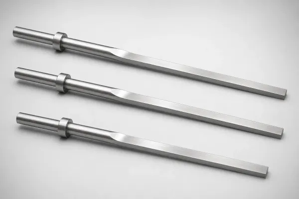
The trade is wear and cost. Beryllium copper is softer than hardened tool steel and wears faster at gate-adjacent locations, so it earns its place under bosses and ribs, not at gate impingement zones. Typical practice seats the insert in a hardened steel pocket, with cavity steel hardened to the HRC 58 to 62 range for gloss surfaces and long runs. High-conductivity cores also cut cycle time, which pays for the insert on high-volume parts.
Cooling asymmetry between the visible side and the hidden side is a mold decision. A part that sinks on a visible gloss face can often be flipped by moving heat to the hidden side. Cool the visible cavity and insulate or warm the core behind the boss. The dip then moves to the surface nobody sees. That is a cooling-circuit spec written at design time, not a process trick.
Root Causes 7-8: Packing Pressure Window and Material Shrinkage
Two root causes remain: the pressure window the mold offers during packing, and the amount of shrinkage the material brings into the cavity. Both are specified before the tool ships.
Root Cause 7: A packing window the mold cannot deliver. Hold pressure is a process setting, but whether it reaches the sink zone is a mold dimension. Pressure drops along the runner, and the drop scales steeply with length and inversely with runner radius. A long cold runner with a small sprue can eat most of the packing pressure before it reaches a distant boss. Gate freeze time sets the end of the window: hold time past gate freeze is wasted.
Mold-side fixes start with full-round runners sized for the flow length. Keep gate depth at 50 to 80% of wall with short polished lands. The gate should freeze after the sections it feeds.
Specify the trial sequence so the window is proven. Raise hold pressure and extend hold time at T1 and watch the sink. If the sink does not respond, the gate froze or the runner choked, and the fix is steel, not more machine settings. If it responds, the mold is capable and the process can carry the part.
Root Cause 8: Material shrinkage class. Semicrystalline resins shrink more than amorphous ones and keep shrinking after the skin freezes, which is why they sink deepest. Published mold-shrinkage ranges for typical grades run wide. Polypropylene sits at 1.5 to 2.5%, POM at 1.8 to 2.2%, and PA66 at 1.2 to 2.0%. Polycarbonate runs 0.5 to 0.7%, and glass-filled PBT runs 0.3 to 0.9%.
A high-shrink resin on a thick boss is the worst combination in this article. Fillers cut the risk: glass and mineral fillers reduce shrinkage and stiffen the skin, which is why the same geometry sinks less in PBT-GF30 than in unfilled PP. Material selection happens before the mold contract, so lock the grade before the cavity is compensated. Our five shrinkage compensation rules cover the cavity math for rates from 0.3% to 2.0%. When a gloss housing can run in either of two resins, the lower-shrink one is the cheaper mold decision even if the pellet price is higher.
How Much Sink Is Visible: Thresholds by Surface
Visibility is the acceptance test, and it depends on surface finish more than sink depth. On high-gloss piano surfaces, sinks read from roughly 0.01 to 0.025 mm because the flat reflection bends at the dip edge. A textured or satin finish breaks up the reflection and hides sinks two to four times deeper. The industry rule of thumb is that 0.025 mm and up reads on gloss, and 0.05 to 0.1 mm reads on most matte surfaces. Set the threshold on the drawing, not at the trial.
Measurement is part of the spec. Sink depth is read with a profilometer, an optical 3D scanner, or a stylus gauge across the feature, and a raking light makes shallow dips visible to the eye. Trial plaques should include the worst-case geometry: the deepest boss and the widest rib, molded in the final resin and final surface finish.
Match the material to the risk before the trial. This table summarizes typical published mold-shrinkage ranges and the sink risk each class carries.
| Material | Typical Mold Shrinkage | Relative Sink Risk | Mold-Side Notes |
|---|---|---|---|
| PP | 1.5-2.5% | High | Gate on every sink zone; generous hold window |
| POM | 1.8-2.2% | High | Thick bosses need core-out and BeCu support |
| PA66 | 1.2-2.0% | Medium-High | Rib ratio and gate depth decide the outcome |
| PC | 0.5-0.7% | Low-Medium | Gloss surfaces still catch shallow sinks |
| PBT-GF30 | 0.3-0.9% | Low | Glass cuts shrinkage; watch abrasive wear on steel |
← swipe to scroll →
Table: Typical published mold-shrinkage ranges for common injection grades. Verify your grade datasheet before setting cavity compensation or sink acceptance values.
Read the table with the geometry rules: high-shrink resin plus a heavy local section is a doubled risk, and no amount of packing fully erases it. Low-shrink resins on clean geometry rarely sink enough to see. The acceptance number belongs in the mold spec, with the surface named and the measurement method agreed.
The DFM Checklist to Send Your Mold Maker
Sink prevention is decided in the documents that move before steel: the part drawing, the DFM review, and the mold specification. Send this checklist with your RFQ and require the mold maker to answer each line before cutting cavities.
- Wall map: every nominal wall listed with target 2 to 3 mm typical, and the maximum-to-minimum transition held under 2 to 1.
- Rib geometry: every rib and gusset base drawn at 0.5 to 0.6x nominal wall, not left to the mold maker's discretion.
- Boss geometry: boss walls near 0.6x nominal wall, with core-out holes specified for screw bosses.
- Thick sections: every local section above roughly 1.5x the adjacent wall flagged with its mitigation plan.
- Gate plan: gate location on or near each sink-critical feature, with gate type and depth at 50 to 80% of wall.
- Fill balance: for multi-cavity tools, the runner layout, natural balance method, and fill-time spread target.
- Cooling plan: channels 2 to 2.5x their diameter from the cavity surface, including core-side cooling under bosses.
- Steel and inserts: cavity steel hardened to the HRC 58 to 62 range, with beryllium copper inserts under high-heat bosses.
- Temperature control: cavity temperature uniform within about ±5 °C, with independent cavity and core circuits.
- Trial acceptance: maximum sink depth on named surfaces, typically 0.025 mm on gloss, measured by an agreed method at T1.

Require the mold maker to return a gate and cooling layout with the DFM response, not just a quote. A mold flow analysis at this stage shows where the last-filled zones sit and whether the gate plan can pack them. The analysis costs days at the drawing stage and saves a tool revision at trial.
DieStrike builds sink-critical tooling under IATF 16949 across 120+ machines. Geometry holds ±0.005 mm standard and ±0.002 mm precision, with molds delivered in 2 to 5 weeks and standard mold parts in 3 to 7 days. The same review discipline that gates connector programs applies to any gloss housing with a boss behind it.
FAQ: Sink Marks in Injection Molded Parts
Q1. How deep does a sink mark need to be before it is visible?
On high-gloss surfaces, sinks read from roughly 0.025 mm up, and some piano finishes catch dips at 0.01 mm. Textured and matte finishes hide deeper sinks, often 0.05 to 0.1 mm. Set the visibility threshold for your actual surface finish and write it into the trial acceptance criteria.
Q2. What is the difference between a sink mark and a void?
A sink is a surface depression where the skin was pulled inward. A void is an internal cavity left inside the thick section. Both come from a section that cannot be fully packed. When the skin is thick and stiff, the center tears open into a void. When the skin is thin or warm, it dips into a sink, and cooling layout decides which side yields.
Q3. How thin can a rib be before it loses its function?
Keep the rib base at 0.5 to 0.6x the nominal wall, the typical published rule. Structure comes from rib height, count, and gussets, not from base thickness. If a 0.6x rib is not stiff enough, add another rib rather than fattening the first one. A boss at about 0.6x wall with a core-out hole keeps the screw support without the sink.
Q4. Can the process engineer fix a sink without changing the mold?
Sometimes, and only when the mold is capable. Raising hold pressure and extending hold time packs the cavity if the gate stays open and the runner delivers pressure. When the sink does not respond to longer hold time, the gate froze early or the runner choked, and the fix is a mold change. That trial test separates process issues from tooling issues.
Q5. When is a beryllium copper insert worth the cost?
When a boss or rib base cannot be cooled by a straight channel and sits under a visible surface. Beryllium copper conducts 105 to 130 W/m·K against 25 to 30 W/m·K for tool steel, pulling heat out of the feature base about four times faster. Use it in hardened steel pockets, away from gate impingement, and the cycle-time saving often pays for the insert on high-volume parts.
Q6. Which single mold specification most often prevents sink marks?
Gate position and size on the largest thick section. A gate placed at the sink-critical feature with a depth of 50 to 80% of wall keeps packing alive until the section freezes. Geometry ratios at 0.5 to 0.6x wall are the other half of the answer, and both belong in the DFM review before steel is ordered.
The Bottom Line
Sink marks are designed in, then fed or starved by the mold. The drawing decides the risk: rib bases at 0.5 to 0.6x wall, boss walls near 0.6x, uniform 2 to 3 mm walls, and transitions under 2 to 1. The mold then decides whether the risk becomes a defect.
Gate the thick zone and size the gate at 50 to 80% of wall so packing arrives before freeze-off. Balance multi-cavity fill, run cooling channels 2 to 2.5x their diameter from the surface, and pull heat from under bosses with baffles or beryllium copper inserts. Match the shrinkage class to the geometry. Prove the packing window at T1. Accept parts against a measured sink depth on the named surface, typically 0.025 mm on gloss.
Every one of those decisions is a mold specification made before steel. A buyer who sends the DFM checklist with the RFQ and gets a gate and cooling layout back will not scrap a gloss housing over 0.05 mm dimples. DieStrike builds these molds under IATF 16949 across 120+ machines, with ±0.005 mm standard geometry, ±0.002 mm precision, and 2 to 5 week delivery. Connector OEMs including TE Connectivity, Amphenol, and Luxshare run sink-critical programs on the same tooling discipline.
KEEP READING
Related Reading
5 Mold Cooling Channel Design Tips for Faster Cycles
Cooling channel diameter, depth from cavity surface, and circuit balance decide cycle time and part quality. Five rules for channels that cool ribs and bosses evenly.
Read articleArticleHow to Balance Multi-Cavity Molds: Runner, Gate and Cooling
Cavity-to-cavity fill balance prevents the starved cavities that sink first. Runner sizing, natural layouts, and gate tuning for consistent packing across the tool.
Read articleArticlePolypropylene (PP) Injection Molding: Grades & Processing
PP shrinks 1.5 to 2.5 percent and sinks faster than almost any other resin. Mold-side rules for a high-shrink material that tests every gate and cooling decision.
Read articleServiceMold Design & DFM
DFM review that flags sink-prone ribs, bosses, and gussets before steel is ordered, then locks gate, cooling, and packing windows into the mold spec.
Read articleNEXT STEP
Ready to Start Your Mold?
Send us your element dimensions or part numbers — our team responds within 24 hours with pricing and lead time.

Written by
Ray ChanMold Buyer's Guide Author · Precision Mold Manufacturing Specialist. Ray helps global importers, distributors and OEMs source factory-direct molds and mold parts.