
How to Calculate Press Tonnage for Stamping Dies
Table of Contents
A 1.5 mm stainless progressive die was booked on a 20-tonne press because the quote sheet measured one blank perimeter. Four stations cut in the same stroke, and the true peak demand was 250 kN, or 25.5 tonne. On tryout the slide stalled 12 mm above bottom dead center, the hydraulic overload dumped, and the corner punch cracked through the heel. The rebuild cost more than the press upgrade would have.
That number was wrong on paper before any steel was cut. Press tonnage for stamping dies is not a guess and not a rule of thumb by part size. It is a sum of forces: shear force at every cutting station, plus bend and draw loads, plus stripper and cushion loads, plus a margin. This article gives the formulas, two complete worked examples, and the press matching checks that decide whether a die can physically be run on the machine it was quoted for.
This is the stamping side of press sizing. The injection side uses a different model entirely, because melt pressure replaces shear force, and that math is covered in our clamp tonnage guide. Steel grades for the punches that carry these loads are covered in our stamping die steel guide.
The Snapshot
- Shear force equals cut perimeter x stock thickness x shear strength. A 50 mm disc in 2 mm mild steel cuts at 97.4 kN, or 9.9 tonne, before any margin.
- Shear strength runs 0.6 to 0.8 of tensile strength: about 310 MPa for mild steel, 520 MPa for 304 stainless, 165 MPa for 5052 aluminum and 150 MPa for annealed copper.
- Stripper force adds 10 to 20% of the cutting load, and a practical sizing margin adds 30%, so 9.9 tonne of shear becomes a 14.8 tonne press demand.
- Staggering stations or grinding shear on punch faces cuts peak force by 30 to 50%, often cheaper than buying the next press class.
- Keep peak demand at or below 60 to 70% of press rating for continuous stamping, and verify die weight, press bed size, shut height and stroke before the press is booked.
Why Press Tonnage Math Decides Die Life
Press sizing has two failure directions and both are paid in cash. An undersized press stalls at the instant of peak load, and the shock travels through the punches. An oversized press runs every stroke at the hourly rate of a machine the die never needed. Stamping is less forgiving than molding on the first direction, because the load arrives in milliseconds and the press cannot stretch capacity the way an injection unit can.
The load a stamping press sees is not the average force over the stroke. It is the peak force at the moment the punch tips enter the stock and the fracture front propagates. On a mechanical crank press that peak happens near mid-stroke on the down travel, where the crank arm has the least mechanical advantage. A die that averages 100 kN over 60 mm of stroke can still demand 250 kN for 6 mm of that stroke, and the press frame and drive see the 250 kN.

The cost asymmetry is real but small compared with a stall. Shop rates rise with press class, and the gap between a 60-tonne and a 200-tonne mechanical press is typically USD 25 to 55 per hour in press time before energy. Booking 40 tonne of headroom you do not need costs money, but booking a press that stalls costs the overload protector, the punch block and the tryout week. Every tonnage number belongs on the die spec sheet next to the press class, not in a spreadsheet someone opens after the die is built.
The Shear Force Formula: Perimeter, Thickness, Shear Strength
Every cutting operation in a stamping die, whether blanking, piercing, notching or trimming, is sized with one formula:
F = L x t x Ss
F is the shear force in newtons. L is the total cut perimeter in millimeters, measured around the profile that separates from the strip. t is the stock thickness in millimeters. Ss is the shear strength of the sheet material in megapascals, which is newtons per square millimeter. The unit check is simple: mm x mm x N/mm2 gives newtons.
The cut perimeter is not the part perimeter alone. A blanking station cuts the outside profile of the part, a piercing station cuts the inside holes and slots, and a trim station cuts the carrier and web. A part with four 6 mm holes adds 4 x 18.85 = 75.4 mm of perimeter to the blank profile. Complex profiles come straight from the CAD flat pattern, and the widely used shortcut is to measure the outline with the CAD measure tool rather than estimate.
Shear strength is the correct material property, not tensile strength. Cutting happens by shear along a narrow band ahead of the punch edge, so the resistance is lower than the tensile value. Published practice puts shear strength at 0.6 to 0.8 of ultimate tensile strength for most sheet metals, and 0.8 of UTS is the safe upper end for stainless and high-strength grades. Using UTS directly in the formula oversizes the press by 25 to 40%, which has cost plenty of buyers a press class they did not need.
A sharp die with correct clearance cuts at a factor of 1.0. A die near the end of its regrind interval cuts at 1.1 to 1.3, because dull edges crush before they shear and the fracture zone widens. Sizing on the dull condition is the conservative choice, and it also covers the clearance spread across a long-run progressive die.

Convert to press tonnage at the end of the sum: 1 tonne of press rating equals 9.81 kN. A 250 kN demand is 25.5 tonne. Never size the press in kN and order in tonne without the conversion, a mismatch that has booked 25 tonne dies on 25 kN thinking.
Typical Shear Strength Values for Common Sheet Metals
Use the supplier datasheet when it exists, because tempers and coatings move shear strength by 10 to 20%. The values below are typical room-temperature figures for standard tempers, and they are accurate enough for press sizing when a datasheet is not available at quote time.
| Sheet Material | Typical UTS (MPa) | Typical Shear Strength Ss (MPa) | Notes for Press Sizing |
|---|---|---|---|
| Mild steel DC01, SPCC, 0.8 to 2 mm | 300-400 | 310 | Baseline for brackets, covers and general parts |
| Deep-draw mild steel DC04, DC05 | 280-350 | 250 | Lower Ss but higher draw load share |
| HSLA 340 to 440 grades, 1.5 to 3 mm | 440-550 | 350-420 | Automotive structural and seat parts |
| 304 stainless, annealed | 520-750 | 520 | Also work hardens, so edge radius grows fast |
| 430 stainless, annealed | 450-520 | 310 | Lower load than 304, used for appliance trims |
| Aluminum 5052-H32 | 230-270 | 165 | Low load, but edges smear without polish |
| Aluminum 6061-T6 | 310 | 210 | Temper matters, T4 cuts at about 60% of this |
| Copper C11000, annealed | 220-250 | 150 | Busbars and terminals, soft and gummy |
| Brass C26000, half hard | 370-460 | 260 | Higher load than copper, cleaner cut edge |
← swipe to scroll →
Table note: typical room-temperature values for standard tempers, with Ss taken at 0.6 to 0.8 of UTS. Confirm against the mill certificate or supplier datasheet before final press booking, because temper, thickness and coating shift Ss by 10 to 20%.
Worked Example 1: Blanking a 50 mm Disc From 2 mm Mild Steel
The simplest tonnage calculation in a stamping shop is a round blank on a single-station die. The part is a 50 mm diameter disc, 2 mm thick, in DC01 mild steel, with a 1.0 mm clearance per side and a 15% stripper load. Work the numbers in order.
Step 1, perimeter. L = pi x 50 = 157.1 mm. For a rectangle it would be 2 x (a + b), and for a CAD profile you measure the outer loop directly.
Step 2, shear force. F = L x t x Ss = 157.1 x 2 x 310 = 97,400 N, or 97.4 kN. That is the force to separate the disc from the strip in one stroke with sharp edges.
Step 3, tonnage. 97.4 kN / 9.81 = 9.9 tonne of shear load at the press.
Step 4, stripper load. The stripper must pull the strip off the punch, and the load is 10 to 20% of the cutting force. At 15%, add 14.6 kN, for 112 kN total, or 11.4 tonne.
Step 5, safety margin. Multiply by a 1.3 sizing margin for dull edges, thicker stock at the top of tolerance and press wear. 112 x 1.3 = 145.6 kN, or 14.8 tonne.
Step 6, press class. A 16-tonne press covers the intermittent case at 93% of the 145.6 kN demand, which is too tight for production. A 20-tonne press holds the peak at 74% of rating, acceptable for single-stroke or slow runs. For continuous running at 300 strokes per minute, keep the peak under 60% of rating, so the floor becomes 145.6 / 0.6 = 243 kN, or a 25-tonne class press.
The same die also has to fit the machine. A single-station blank die of this size weighs about 180 to 250 kg. It fits a 400 x 250 mm press bed with margin, and needs 15 to 25 mm of cutting stroke. Stripping and clearance add another 20 to 30 mm. Those checks are covered further down. What matters here is that the arithmetic never stops at step 2. The stripper, the margin and the utilization limit together doubled the answer.
Cutting Peak Force 30 to 50%: Staggered Punches and Shear Grinding
The formula gives the static force of a flush cut, where the whole perimeter breaks at once. Almost no production die cuts that way. Two standard tricks spread the cut over time and cut the peak, and both are cheaper than the next press class.
The first is staggering. In a progressive die, the designer offsets the cutting stations in stroke position so that only part of the total perimeter fractures in any 1 to 3 mm of slide travel. Offsetting stations by 2 to 4 mm of stroke, or splitting a long trim into two stations 3 to 5 stations apart, typically reduces peak shear force by 30 to 40% with no change to the total work. The cycle time is unchanged because each station still cuts once per stroke.
The second is shear grinding, or shear on the punch face. Grinding an angle or a stepped form across the punch face makes the edge contact the stock progressively, like a guillotine blade. A shear height equal to 40 to 65% of stock thickness reduces the peak blanking force by 40 to 50% on thick stock. For a 2 mm mild steel cut at 97.4 kN, a 1.0 mm shear ground across the punch face brings the peak to roughly 50 to 60 kN.

Shear grinding has costs. The sheared edge is not straight in the stroke direction, so a part with a flatness or burr requirement on the cut face may need the shear on the scrap side only. Shear also reduces effective punch life on thin stock below 0.8 mm, where the reduced edge support causes chipping. Grind shear for thickness above about 1.2 mm and for heavy cuts, and stagger stations for everything else.
Adding Bend Force, Drawing Force and Blank Holder Force
Cutting is not the only load in the stroke. A forming or draw station adds force that peaks at a different point in the stroke, and on a progressive die the moments overlap enough that both must be summed into press tonnage.
Bend force. Free or air bending uses F = (K x L x t2 x UTS) / (r + t). L is the bend length, r is the inside bend radius, and UTS is tensile strength. K is 1.33 for air bending and 1.2 for bottoming. A 40 mm bend in 1.5 mm 304 stainless at UTS 700 MPa and a 1.5 mm inside radius gives F = 1.33 x 40 x 2.25 x 700 / 3.0 = 27,930 N. That is 27.9 kN. V-die bending against an opening width W uses the same form with W in place of (r + t). The answer comes out 15 to 25% different.
Drawing force. The first draw uses F = pi x d x t x UTS x (D/d - 0.7), where d is the punch diameter and D is the blank diameter. A 50 mm cup drawn from a 100 mm blank in 1.0 mm DC04 at UTS 350 MPa gives F = 3.14 x 50 x 1.0 x 350 x (2.0 - 0.7) = 71,470 N, or 71.5 kN. The draw ratio D/d of 2.0 sits at the practical first-draw limit for mild steel. Stainless limits the first draw to 1.6 to 1.8, and exceeding that ratio is a cracking problem, not a tonnage problem.
Blank holder force. The blank holder adds its own load, calculated as ring contact area times holding pressure. The ring area for a 100 mm blank around a 56 mm ring is pi / 4 x (1002 - 562) = 5,391 mm2. At a typical holding pressure of 2 to 3 MPa for mild steel, that is 13,478 N, or 13.5 kN.
Add the draw and blank holder together and the draw station needs about 85 kN, roughly 8.7 tonne, before any margin. A die that blanks at 97 kN in one station and draws at 85 kN in another demands 182 kN if both peaks land in the same stroke window, which is common on short-pitch progressive dies. That is why the tonnage sheet lists station loads separately, not as a single part number.
Stripper Force, Impact Load and the Air Cushion
The stripper is the component that decides whether a tonnage number survives contact with production. Its load is not optional and not small. Stripper force runs 10 to 20% of the cutting force, and it must be available at the exact point in the upstroke where the strip grips the punch.
Spring strippers on a progressive die are usually preloaded coil springs or nitrogen gas springs. Nitrogen springs hold 8 to 15% more force over the full stroke than coil springs of the same envelope. That matters when the stripper travel exceeds 20 mm. A 97.4 kN cutting load needs 10 to 20 kN of stripping force per station. Undersized springs show up as pulled strip, bent pilots and, in the worst case, a strip carried into the next stroke.
Impact is the second load the static formula misses. At 200 to 400 strokes per minute the slide decelerates through the cut, and the dynamic factor runs 1.3 to 1.5 times the static shear force. A 97.4 kN blank becomes 127 to 146 kN of real load on a high-speed press. Sizing only the static number on a high-speed line is one of the most common causes of overload trips on otherwise healthy presses.
The air cushion is the third component, and it works in the opposite direction. A press cushion is a die cushion mounted in the bed or bolted to the bolster, and it holds the blank or the part during draw and ejecting cut-outs. Cushion rating is typically 10 to 20% of press tonnage, so a 40-tonne press carries a 4 to 8 tonne cushion, adjusted through air pressure in the 0.3 to 0.6 MPa range. Cushion force loads the press on the down stroke, so it belongs in the peak tonnage sum whenever it is active during the cut or form. A die with a 40 kN cushion draw and a 97 kN blank in the same stroke sums to 137 kN, then gets the safety margin.
Safety Margin and Tonnage Utilization Limits
The sizing margin covers everything the formula cannot see: material at the top of the thickness tolerance, shear strength at the upper end of the range, dull edges, uneven strip thickness across the coil, and press wear. Published practice uses a margin of 1.2 to 1.4 on the summed static load, and 1.3 is the working default for a progressive die that will be reground for years.
Margin is not the same as capacity. A press rated at 40 tonne is not meant to deliver 40 tonne on every stroke for a shift, and running there destroys the drive. Peak tonnage utilization is limited by press type and speed, and the limits below are the practical figures used when booking a machine.
| Press Duty | Max Peak Tonnage Utilization | Why the Limit Sits There |
|---|---|---|
| Mechanical press, single stroke or manual feed | up to 80% | Low stroke count, frame and drive recover between hits |
| Automatic progressive die, up to 150 SPM | 60-70% | Continuous duty heat build-up in the clutch and bearings |
| High-speed progressive, 200 to 400 SPM | 50-60% | Dynamic impact factor of 1.3 to 1.5 on every cut |
| Fine blanking, coining or cold forming in the die | 50-60% | Peak load is near bottom dead center, worst crank leverage |
| Hydraulic overload protector trip setting | 110% of rating, never a sizing target | Trips to protect the press, not to schedule production |
← swipe to scroll →
Table note: typical utilization limits by press duty. Confirm the actual figure in the press manual, because frame stiffness, flywheel energy and overload setting vary by builder and machine age.
Energy capacity is a separate gate from tonnage. A flywheel press has to deliver the work of the cut, and a short, very heavy cut can trip the press on energy even when the tonnage chart looks fine. Flywheel energy is usually stated in the manual in joules or in kilogram-meters, and a die that needs 900 joules per stroke on a press with 600 joules available is not a press that can run it, whatever the tonnage rating says.
Worked Example 2: Progressive Die Resultant and Center of Pressure
The second example is a five-station progressive die cutting 1.5 mm 304 stainless at Ss 520 MPa and UTS 700 MPa, with a 45 mm pitch and a 40 mm bend in the last station. Every station is sized with the same formula, then the loads are summed at the stroke position where they overlap.
Station 1, two pilot holes at 3.5 mm. Perimeter 2 x pi x 3.5 = 22.0 mm, so F = 22.0 x 1.5 x 520 = 17,160 N, or 17.2 kN.
Station 2, two holes at 6 mm. Perimeter 2 x pi x 6 = 37.7 mm, so F = 37.7 x 1.5 x 520 = 29,406 N, or 29.4 kN.
Station 3, notch trim. Perimeter 45 mm, so F = 45 x 1.5 x 520 = 35,100 N, or 35.1 kN.
Station 4, blank. Perimeter 180 mm, so F = 180 x 1.5 x 520 = 140,400 N, or 140.4 kN. This single station carries 63% of the cutting load.
Station 5, bend. F = 1.33 x 40 x 2.25 x 700 / 3.0 = 27,930 N, or 27.9 kN.
The cutting stations alone total 222.1 kN. Add the bend and the sum is 250 kN, or 25.5 tonne of static load. Stripping at 15% of the cutting force adds 33.3 kN, taking the peak to 283 kN, or 28.9 tonne. Apply the 1.3 sizing margin and the press demand becomes 368 kN, or 37.5 tonne.

Press class. A 40-tonne press rated 392 kN would run the die at 94% of rating after margin, which is not acceptable. The 63-tonne class at 618 kN holds the same load at 46% of rating, which leaves room for 150 to 300 strokes per minute and for a dull die at the end of its regrind interval. This is the number the quote sheet should have carried in the opening example, where a 20-tonne press was booked against 250 kN of demand.
Center of pressure. Load must be centered, or the slide tips and the die deflects unevenly. Take moments about station 1, with stations at 0, 45, 90, 135 and 180 mm:
M = (17.2 x 0) + (29.4 x 45) + (35.1 x 90) + (140.4 x 135) + (27.9 x 180) = 28,458 kN-mm. Divide by the 250 kN total and the center of pressure sits 113.8 mm from station 1, while the strip center sits at 90 mm. The blank station pulls the resultant 23.8 mm toward the back of the die.
Align the die on the bolster so that point meets the press centerline. Eccentricity limits are typically 5 to 10% of the bolster span. At 23.8 mm the value is acceptable on an 800 x 500 mm bed, but it must be planned, not left to the clamping slots. Shift that resultant 60 mm off center and the tipping moment becomes 250 kN x 0.06 m = 15 kN-m on the slide guides. That shows up as uneven guide wear and a die that cuts clean on one side and tears on the other.
Matching Die Weight, Press Bed Size, Shut Height and Stroke
Tonnage gets the die on the shortlist. Four more numbers decide whether it can actually be bolted down and run, and each of them is a real rejection reason at the tryout stage.
Press bed size and bolster area. The die footprint must fit inside the bed with room for clamps, typically 50 to 100 mm of clear margin on each side. A 60-tonne class press carries a bed around 800 x 500 mm and accepts a die up to about 700 x 420 mm. Footprint is not only about fitting, because a bed deflects under load, often 0.05 to 0.1 mm across the face. A die that covers a third of the bed concentrates its load in the middle and needs support blocks or shims at the edges to keep the plates flat.
Die weight. Slide and bolster load capacity is a nameplate number that most tonnage sheets ignore. A 60-tonne press usually supports 1.5 to 2.5 tonne of upper die weight, and a 200-tonne press 5 to 10 tonne. A five-station progressive die in the example above weighs 2.5 to 4 tonne complete, which is within the capacity of the 63-tonne class press but needs a handling plan. Crane capacity, die cart rating and the available lift height all belong in the same checklist as tonnage.
Shut height. The closed die height must fall inside the press adjustment range, often 250 to 320 mm on a 60-tonne class mechanical press. A die 10 mm too tall cannot be run at all, and a die 30 mm too short needs a spacer bolster plate that costs height accuracy. Regrinding eats into this margin, because each regrind removes 0.1 to 0.3 mm from the die block and cumulative stock removal over ten regrinds reaches 1 to 3 mm. Ask for 40 to 80 mm of shut height adjustment so the die survives its full regrind life.
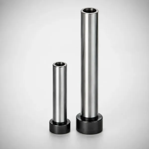
Stroke. Stroke length must cover the cut depth plus forming depth plus stripping travel plus strip lift, and the strip lift alone runs 3 to 8 mm on a progressive die with a fixed feed line. A crank press has a fixed stroke, so a die that needs 90 mm of working travel cannot be squeezed onto a 60 mm stroke machine, whatever its tonnage. Matching work at this stage is where stamping die manufacturing earns its keep, because the press list, the tonnage sheet and the die height all have to agree before steel is cut.
Undersized vs Overloaded: How the Math Fails in Practice
Bad tonnage math produces two distinct failure families, and the damage tells you which one you have.
Insufficient tonnage for the die demand. The press cannot complete the cut, so the slide stalls near bottom dead center with the punches buried in the stock. On a mechanical press the flywheel energy dumps into the frame in a fraction of a second, and the overload protector trips at 110% of rating. Every cycle before the trip leaves parts with torn edges, incomplete cuts and burrs on the shear face. The shock load also breaks punches, usually at the shank or the heel of a corner punch, and cracks appear in the punch retainer. Repeating the stall one more time is how a press loses a connecting rod.
Die deflection from undersized tooling on a big press. A light die on a heavy press is the mirror problem. The extra tonnage available does not get used, but the die plates flex under a load they were never sized for, punch-to-die alignment drifts, and galling starts on the punch flanks. Clearance control is the first thing to fail, and our punch clearance guide covers the measurement routine that catches it.
Overload damage to the press. When the protector is shimmed, taped or defeated, the peak travels into the drive. A mechanical press overload deforms the connecting rod or crankshaft, stretches the frame and scores the slide guides. Repair means a stripped press and weeks of downtime, not a new punch. No die is worth running past the 110% trip point, and the sizing margin exists so that nobody is tempted to try.
DieStrike builds stamping dies against a tonnage sheet that lists each station load, the press class and the center of pressure. DFM feedback comes back within 24 hours of the drawing set, die dimension accuracy holds at ±0.005 mm and die components at ±0.002 mm geometry, with forming and cutting inserts heat treated to HRC 62. Stamping die lead time runs 2 to 5 weeks, and standard components such as punches, die springs, guide posts and die sets ship in 3 to 7 days. Programs for connector and automotive customers including TE Connectivity, Amphenol, Luxshare and Dongshan Precision are sized this way before the first cut.
Press Tonnage FAQ
Q1. What is the formula for press tonnage on a blanking die?
Multiply the cut perimeter by the stock thickness by the shear strength, then add stripping at 10 to 20% and a 1.3 margin. A 50 mm disc in 2 mm mild steel at Ss 310 MPa gives 157.1 x 2 x 310 = 97.4 kN, which becomes 14.8 tonne after stripper and margin, so a 20-tonne press is the working floor for slow runs.
Q2. How much does staggered punching reduce press tonnage?
Staggering cutting stations across the stroke cuts peak force by 30 to 40%. Shear grinding 40 to 65% of stock thickness across the punch face cuts it by 40 to 50% on stock above 1.2 mm. Total work is unchanged, so flywheel energy demand stays the same.
Q3. How much safety margin should I add when sizing a press?
Use 1.2 to 1.4 on the summed static load, with 1.3 as the working default. Then check utilization: under 60% of rating for high-speed runs above 200 strokes per minute, 60 to 70% for automatic progressive work, and up to 80% only for single-stroke operation.
Q4. Why does the overload trip when the tonnage math looks fine?
Four usual causes: the dynamic impact factor of 1.3 to 1.5 at high stroke rates, cushion force left out of the sum, off-center loading beyond 5 to 10% of the bolster span, and flywheel energy limits on very heavy cuts. Check the die weight and press bed size fit as well. A die that overhangs the bed loads the frame unevenly.
Q5. What shear strength should I use for sizing when there is no datasheet?
Take 0.8 of the tensile strength as a safe upper bound and 0.6 as the low end for soft tempers. Typical working values are 310 MPa for mild steel, 520 MPa for 304 stainless, 210 MPa for 6061-T6 aluminum and 150 MPa for annealed copper.
The Bottom Line
Press tonnage for stamping dies is a sum, not a lookup. Add the shear force at every station to the bend, draw, blank holder, stripper and cushion loads. Multiply by a 1.3 margin, then check utilization, die weight, press bed size, shut height and stroke. Size it on paper and the die runs for its full regrind life. DieStrike builds dies to those numbers, and reviews the tonnage sheet at DFM stage before cutting steel.
KEEP READING
Related Reading
How to Calculate Clamp Tonnage
Injection clamp force from projected area and cavity pressure, with the safety margin rule for molding presses.
Read articleArticleHow to Select Stamping Die Steel
D2, A2, M2, PM-HSS and carbide by station duty, run length and shear strength of the stock.
Read articleArticleHow to Build a Progressive Die
The 8-step build sequence from strip layout to tryout, with cutting clearance and spring setup values.
Read articleServiceStamping Die Manufacturing
Progressive, compound and transfer die design and build with tonnage and press matching on the drawing.
Read articleNEXT STEP
Ready to Start Your Mold?
Send us your element dimensions or part numbers — our team responds within 24 hours with pricing and lead time.

Written by
Ray ChanMold Buyer's Guide Author · Precision Mold Manufacturing Specialist. Ray helps global importers, distributors and OEMs source factory-direct molds and mold parts.