
How to Design Transfer Mold Tooling: Ports, Pistons and Cavities
Table of Contents
A transfer tool that lets the piston clearance open to 0.25 mm pushes a 0.5 mm flash collar up the pot wall on every shot. Trimming that collar costs 20 to 40 seconds per part, and on a 4-cavity encapsulation tool running 200,000 parts a year one wear allowance decides whether the quoted piece price holds. This guide sets the pot, piston, port and cavity numbers for thermoset and LSR transfer tooling.
Every figure below is a typical value for pot-and-piston transfer molding, to check against the compound datasheet and the press before a drawing is released.
The Snapshot
- Transfer pressure of 70 to 140 bar. A 100 mm pot needs about 78 kN of piston force to hold 100 bar, and the same pressure packs each closed cavity through a 0.8 to 2.5 mm port.
- Piston clearance of 0.05 to 0.15 mm. Below 0.05 mm the piston seizes as the pot reaches 150 to 180 °C, and above 0.15 mm a flash collar of 0.1 to 0.5 mm climbs the wall.
- Charge volume of 1.10 to 1.30 x the part. The pot holds cavity volume plus runner volume plus a 3 to 8 percent residue allowance, and the piston stroke sets the usable pot depth.
- Cycle of 10 to 40 percent under compression. Cure starts in the 165 to 180 °C transfer channel, so a 3 to 6 mm wall gels sooner than an open compression charge at the same plate temperature.
Where Transfer Molding Sits
A transfer tool closes on empty cavities while the charge waits in a heated pot above the parting line. The piston descends at 2 to 15 mm/s and pushes compound through a sprue and a set of ports into closed cavities at 70 to 140 bar. Cure starts inside the transfer channel, so the melt enters each cavity near the plate temperature and gels in 10 to 40 percent less time than an open charge on a 3 to 6 mm wall.
That position defines the route economics. Compression molding drops a weighed preform into an open cavity and closes the press, so the tool is cheap and the cycle is long. Thermoset injection melts and meters with a screw and a runner system, so fill control is tight but the barrel needs purging between grades. Transfer keeps a closed-cavity fill without a screw, and the cured sprue is reground instead of scrapped. The open-cavity route is covered in the thermoset compression mold guide, and the screw route in the thermoset injection mold guide.
| Route | Charge placement | Fill pressure | Cycle versus compression | Scrap and regrind | Tool cost index |
|---|---|---|---|---|---|
| Compression | Weighed preform in an open cavity | 20 to 70 bar clamp | 1.0 baseline on a 3 to 6 mm wall | Flash 3 to 8 percent, no runner | 1x |
| Transfer | Charge in a heated pot, piston pushed | 70 to 140 bar transfer | 0.6 to 0.9 x compression | Sprue and pot residue, 5 to 15 percent | 1.2 to 1.8x |
| Thermoset injection | Metered by screw into a closed cavity | 300 to 1,200 bar at the nozzle | 0.5 to 0.8 x compression | Cull and runner, purge between grades | 1.5 to 2.5x |
← swipe to scroll →
Table note: pressures, cycle ratios and cost indexes are typical industry values by route. Confirm the transfer pressure, the cure schedule and the clamp rating against the press datasheet and the compound supplier data before a tool is released.
Transfer tools usually carry 2 to 12 cavities on one pot. The part families that justify the route are bobbins, brush holders, terminal blocks, sensor bodies, coil encapsulation and LSR seals molded over a metal insert. They share a shape problem: a closed cavity with a small entrance, where an open compression charge cannot be placed by hand on every cycle.

A transfer tool can hold a metal lead frame or a coil at one station and fill around it at 70 to 140 bar, which a compression tool cannot do without moving the insert on the close stroke.
Piston and Pot Arithmetic
The pot diameter runs 50 to 150 mm and follows the charge. Pot area multiplied by piston stroke must cover the charge volume, which is cavity volume plus runner volume, times 1.10 to 1.30. A 100 mm pot gives 7,854 mm2 of piston area, so a 90 cm3 charge needs about 11.5 mm of piston travel.
Size the piston force from the same area. At 100 bar the pressure is 10 N/mm2, and 7,854 mm2 times 10 N/mm2 gives 78.5 kN, or about 8 metric tons on the pot. A tool that needs 140 bar to fill carries 110 kN, so the press transfer cylinder rating sets the pressure ceiling long before the port size does.
Clearance between piston and pot runs 0.05 to 0.15 mm on diameter. A clearance under 0.05 mm leaves no room for the thermal growth of a pot at 150 to 180 °C and the piston seizes mid-stroke. A clearance over 0.15 mm lets compound extrude past the land, and a 0.1 to 0.5 mm flash collar climbs the pot wall and consumes 3 to 8 percent of the charge. Set the cold clearance at 0.08 to 0.12 mm so it lands inside the band when hot.

Wear is measurable and finite. Check the piston-to-pot clearance every 10,000 to 25,000 shots with a feeler gauge or an air gauge, and plan a piston replacement at 0.25 mm. A phenolic with 30 percent glass can reach the limit in 60,000 shots where an unfilled epoxy takes 150,000, so keep the replacement piston and liner as a matched pair and never mix a new piston into a worn bore.
Port and Channel Design
The transfer port is the gate between the runner and the cavity, and it runs 0.8 to 2.5 mm in diameter at the cavity entrance. Flare the upstream side of the port at 30 to 60 degrees so the compound accelerates once and does not shear against a square step. A port under 0.8 mm freezes on a cold tool and starves the cavity. One over 2.5 mm dumps a cold slug and leaves a gate witness the size of a pencil point.
Port velocity is the shear limit that matters on filled compounds. Keep the gate velocity under 15 mm/s, because above that a 30 to 40 percent glass-filled phenolic breaks fiber and loses 15 to 30 percent of its impact strength at the gate. That is the number that rules out a small port on a fast cycle: the piston speed and the port area together set the velocity, so a small port needs a slower piston.

Size the runner so it freezes after the cavity fills, not before. A 3 to 6 mm round runner carries the charge at low shear and then cures last, which is what lets the piston pack the cavity on a 5 to 20 second hold. A runner thinner than 3 mm freezes first, the piston has nowhere to push, and the part shows a density void at the far end.
Keep the channel from runner to cavity at 1.0 to 1.5 x the part wall over the last 10 to 20 mm. A channel at wall size freezes at the same moment as the part and blocks pack-off pressure. At 1.5 x wall the channel stays open 3 to 8 seconds longer than the part and passes the hold. The trade is regrind weight, because a fat channel cures into a heavier cull.
Multi-Cavity Balance
A transfer tool fills every cavity from one piston, so balance is a runner and port problem, not a machine setting. Use a balanced runner layout with equal flow length from the sprue to each port, and keep the runner round at 3 to 6 mm through the whole tree. An unbalanced runner sends more charge to the near cavities on every shot, and the far cavities stay 5 to 20 percent light.
Set the port size from a transfer ratio of 0.05 to 0.15 g of compound per mm2 of projected area, per cavity. A cavity with 2,000 mm2 of projected area needs 100 to 300 g of charge behind it, and the port that feeds it follows from the gate velocity limit.
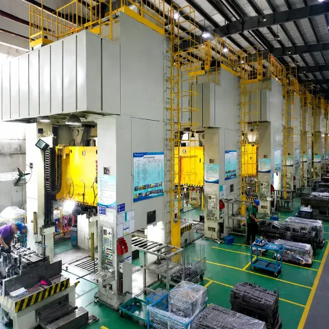
Set the first cut with a deliberate bias and trim it back. Cut the far ports 0.2 to 0.5 mm wider than the near ones on the first steel, then run 20 to 50 shots and weigh every cavity. Bring the wide ports down 0.1 mm at a time until the spread lands inside 5 percent. It is a 2 to 4 hour job on first cut and a 1 to 2 day job if the ports are cut equal and the tool has to come apart again.
Heat Control and Machine Set
Run the mold at 150 to 180 °C, held within plus or minus 3 °C across the cavity block. Run the pot zone 5 to 10 °C hotter than the cavity so the charge stays fluid in the pot and cures in the channel at the same time as the part. A pot 5 to 10 °C hotter shortens the cure 5 to 15 percent without scorching the compound at the port.
Set the clamp tonnage from projected area, not from the last job. Multiply the projected cavity area in mm2 by 70 to 140 bar and add the pot area times its transfer pressure, then divide by 10,000 to read tonnes. A tool with 8,000 mm2 of cavity area at 100 bar needs 80 kN of cavity force, and the pot at 100 mm adds 78.5 kN, so the clamp needs about 16 tonnes plus a 1.5 to 2.0 safety factor.
Set the transfer pressure and the piston speed together from the gate velocity. A 1.5 mm port with 30 mm2 of area at 15 mm/s passes 450 mm3/s of compound, which fills a 2,000 mm3 cavity in about 4.5 seconds. Keep the platens parallel within 0.05 mm, because a hot 150 to 180 °C platen moves the geometry by 0.05 to 0.15 mm and a tilted platen opens a 0.1 to 0.3 mm flash gap on one edge.

A 12-cavity tool caps the cavity count at what the pot can deliver, because every added cavity splits the same piston force. A pot that holds 100 bar across 4 cavities may hold only 70 bar across 12 and fall below the fill threshold on the far end, so the clamp tonnage and the pot pressure belong in the same calculation.
LSR and Encapsulation Transfer Work
Liquid silicone rubber changes two setpoints on the same tool. Run the mold at 150 to 180 °C so the platinum cure completes in 60 to 120 seconds, but hold the pot and the feed system at 20 to 40 °C, because LSR cures at plate temperature and would gel in a hot pot. The pot is then a cold chamber, and the feed channels are cooled, which is the opposite of the thermoset layout.
LSR clearance is tighter than a thermoset. Run the piston-to-pot clearance at 0.05 to 0.10 mm and hold the ports at 0.8 to 1.5 mm, because an LSR at 500,000 cps will not pass a cold 0.5 mm port in a useful cycle time. Feed pressure at the port runs 30 to 90 bar on a cold-runner system, and the cold runner block must sit within plus or minus 2 °C of the setpoint or a partially cured slug blocks a valve gate.
Encapsulation work is a transfer job with a low-pressure ceiling. A coil or a sensor body overmolded at 10 to 40 bar fills the winding without moving a 0.2 mm wire, and the pot feeds 4 to 24 cavities from one piston through a runner tree. The failure to watch is wire sweep: keep the gate velocity under 10 mm/s and the fill front under 10 mm/s, or a 0.05 mm wire displaces and touches its neighbor.
Read the material window before the tool is cut. Cure temperature, shrinkage and the viscosity curve set the pot temperature, the port size and the cure time together, and the LSR material guide carries those curves for the silicone family.
Transfer Mold Defects and Numbers
Transfer molding has a short defect list, and each defect traces to one tool number. The four that stop a line are short shot, density void, flash collar and a knit line where two ports meet. Each one has a measurable cause in the pot, the port or the runner, and each fix is slower than the mistake that created it.
| Defect | Root cause in the tool or set | Number to check |
|---|---|---|
| Short shot | Charge weight low, vent blocked, or pot 5 to 10 °C cold | Charge at 1.10 to 1.30 x cavity plus runner, vent 0.02 to 0.04 mm |
| Density void | Port freezes before pack-off, so the piston has nowhere to push | Hold the piston 5 to 20 s longer, channel at 1.0 to 1.5 x wall |
| Flash collar on the pot wall | Worn piston, clearance grown past 0.15 mm | Replace at 0.25 mm clearance, collar runs 0.1 to 0.5 mm |
| Knit line where ports meet | Two port streams meet cold in a large cavity | Weld is 15 to 30 percent weaker, raise the plate 5 to 10 °C |
| Wire sweep in an encapsulation | Gate velocity above 10 mm/s, or a pot too hot | Fill front under 10 mm/s, pot 60 to 90 °C |
| Scorch at the port | Pot zone more than 10 °C above the plate, or a stalled cycle | Pot 5 to 10 °C above the cavity set, cure 60 to 180 s |
← swipe to scroll →
Table note: causes and thresholds are typical values for phenolic, epoxy and LSR transfer molding. Confirm the charge weight, the pot setpoint and the vent depth from the trial record before changing tool geometry.
Two of those rows are the same number seen from opposite ends. A short shot from a cold pot and a density void from a frozen port both respond to a 5 to 10 °C pot rise before any steel moves, so check the pot setpoint and the actual pot temperature together.
The flash collar is wear, not a setpoint. A piston that has opened to 0.25 mm clearance throws a collar on every shot, and the collar becomes a 20 to 40 second trim per part. Replace the piston on the shot count schedule, before the collar appears.
Tool Steel and Wear Parts
Tool steel for a transfer tool is chosen for wear and for cure chemistry, not for impact. A phenolic or a glass-filled epoxy abrades the port and the pot wall, so use a hardened cavity insert in the 48 to 62 HRC band and a nitrided or PVD-coated pot liner. DieStrike holds plus or minus 0.005 mm mold tolerance, plus or minus 0.002 mm on EDM and jig grinding, and runs cavity heat treatment up to HRC 62.
The pot liner and piston are the wear pair. Run the liner at 50 to 58 HRC and the piston at 48 to 56 HRC so the piston wears before the liner, then hard-chrome or nitride the piston to cut friction. Match the piston and liner as a set and tag them with the pair number, because a piston from one tool rarely fits a liner from another inside the 0.05 to 0.15 mm band.
Ejection takes the last load. A cured thermoset part does not shrink onto the core the way a thermoplastic does, so design 4 to 8 ejector pins or a stripper plate and push on a boss or a wall over 2 mm, never on a 1 mm rib at 150 to 180 °C.
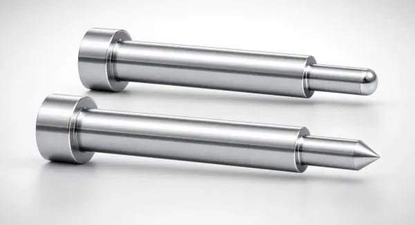
Standard components ship in 3 to 7 days and a full tool runs 2 to 5 weeks from drawing release. Keep a spare piston and liner pair, a spare port insert set and a spare ejector set on the shelf, because a 1 to 2 day change with a spare in the cabinet is a 1 to 3 week wait without one. The pot and piston spare set costs 0.5 to 1 percent of the tool price.
Buyer Rules for a Transfer Tool RFQ
An RFQ for a transfer tool carries four process numbers plus the part print: the compound and its cure profile, the parts per pot, the cavity count and the projected area per cavity. A supplier who is not told the cure profile cannot size the pot zone or the runner freeze.
Ask for the pot and piston arithmetic in the quote. A quote that shows pot diameter, piston stroke, charge volume at 1.10 to 1.30 x the cavity and the port diameter has already done the design. One that shows only a price and a lead time has not.
Demand a pot and piston spare set at 0.5 to 1 percent of the tool price in the same purchase order, plus the clearance the tool ships with and the shot count for the next check. A transfer tool without a matched spare pair stops the line the day the clearance crosses 0.25 mm.
Route the print, the compound cure profile, the cavity count and the volume through injection mold manufacturing or a DFM review before the tool steel is ordered. A DFM pass sets the port diameter, the runner size and the clamp tonnage from the part data, and the potting layout follows from those numbers. A tool that reaches the shop without that pass is a first cut with no balance bias and a 1 to 2 day teardown behind it.
Transfer Tool Design Checklist
Run this list against the drawing before a transfer tool is released. Each line is a number a reviewer reads off the drawing, not a value read off the press after the first shot.
- Pot sizing. Pot diameter 50 to 150 mm, piston stroke covering the charge, charge at 1.10 to 1.30 x cavity plus runner, and a 3 to 8 percent residue allowance.
- Piston and pot clearance. 0.05 to 0.15 mm on diameter, cold set at 0.08 to 0.12 mm, piston length 1.0 to 1.5 x diameter, replacement at 0.25 mm.
- Port diameter and flare. 0.8 to 2.5 mm at the cavity entrance, a 30 to 60 degree upstream flare, and a gate velocity under 15 mm/s on filled compound.
- Runner and channel. 3 to 6 mm round runner, balanced flow length to every cavity, channel at 1.0 to 1.5 x wall over the last 10 to 20 mm.
- Multi-cavity balance. Transfer ratio 0.05 to 0.15 g per mm2 of projected area, far ports cut 0.2 to 0.5 mm wider on the first steel, spread trimmed inside 5 percent.
- Heat zones. Mold at 150 to 180 °C within plus or minus 3 °C, pot 5 to 10 °C hotter for thermoset, pot at 20 to 40 °C for LSR, and a separate control circuit per zone.
- Clamp math. Projected cavity area times 70 to 140 bar plus the pot area load, with a 1.5 to 2.0 safety factor on the press rating.
- Venting. Vents at 0.02 to 0.04 mm at the last-fill corner and along the parting line every 20 to 30 mm, with a clean-out interval on the maintenance card.
- Wear parts and spares. Piston and liner matched as a set, pot liner at 50 to 58 HRC, a spare pair at 0.5 to 1 percent of the tool price, and a clearance check every 10,000 to 25,000 shots.
The checklist is also the tool file, so a transfer tool that carries its pot arithmetic, its port map and its cure schedule in one package runs the same after a shutdown as it did on the trial day.
The Bottom Line
Transfer mold tooling runs on a short list of numbers. Hold the piston-to-pot clearance at 0.05 to 0.15 mm, the transfer port at 0.8 to 2.5 mm with a 30 to 60 degree flare, the channel at 1.0 to 1.5 x wall, and the mold at 150 to 180 °C with the pot 5 to 10 °C hotter. Those four set the fill, the pack-off and the cycle.
The route sits between compression and injection. Transfer buys a 0.6 to 0.9 x cycle against compression and a 1.2 to 1.8x tool cost index, with a closed-cavity fill that holds an insert and a 70 to 140 bar pack. A multi-cavity tool lives or dies on balance, so cut the far ports 0.2 to 0.5 mm wider on the first steel and trim them inside a 5 percent spread.
DieStrike builds transfer, compression and injection tooling under IATF 16949, with plus or minus 0.005 mm mold tolerance, plus or minus 0.002 mm on EDM and jig grinding, HRC 62 cavity heat treatment and 120+ machines. Standard components ship in 3 to 7 days and tool lead times run 2 to 5 weeks, with tier-1 references that include TE, Amphenol, Luxshare and Dongshan.
KEEP READING
Related Reading
How to Design Compression Molds for Thermosets
Open-cavity charge placement, cure per mm of wall and the mold temperature set for phenolic and epoxy parts.
Read articleArticleHow to Design Thermoset Injection Molds: BMC and Phenolic
Screw injection tooling for thermosets: nozzle heat, runner freeze and the purge rules that protect the barrel.
Read articleArticleLiquid Silicone Rubber (LSR) Injection Molding Guide
Cure temperature, shrinkage and viscosity data for the platinum compound that runs through a cold pot.
Read articleServiceMold Design and DFM
IATF 16949 tool design reviews that set pot size, port diameter, clamp tonnage and cure time before cutting starts.
Read articleNEXT STEP
Ready to Start Your Mold?
Send us your element dimensions or part numbers — our team responds within 24 hours with pricing and lead time.

Written by
Ray ChanMold Buyer's Guide Author · Precision Mold Manufacturing Specialist. Ray helps global importers, distributors and OEMs source factory-direct molds and mold parts.