
How to Design Automotive Lighting Molds: Lens Optics and Housings
Table of Contents
A weld line across a headlamp lens can scrap the optical part. Automotive customers reject cosmetic defects at parts-per-million rates. A burn mark on a mirror cavity face cannot be fixed on the press. The steel goes back to the mold shop for a 2 to 5 day re-polish. Lighting tooling therefore wins or fails at the design table, before the first cavity is cut.
The Snapshot
- Lens cavities run in S136 ESR or NAK80 and polish to SPI A1, Ra 0.01 to 0.02 µm typical.
- Optical-grade PC shrinks 0.5 to 0.7%, so cavity steel is scaled before EDM and polishing.
- Gates land off the optical face so weld lines finish behind ribs and edges.
- PC vents run 0.01 to 0.02 mm deep typical, and cooling channels sit 2 to 3 hole diameters from the cavity face.
- Key optical dimensions hold ±0.02 to ±0.05 mm typical, verified by CMM on steel and OGP on molded lenses.
- DieStrike builds IATF 16949 tooling to ±0.005 mm mold accuracy with DFM feedback in 24 hours.
Start with the Optical Zone Map
Classify every surface before steel is ordered. A headlamp outer lens runs 300 to 500 mm long with a 2.5 to 3.5 mm wall. Its outer face is both a styling surface and an optic. Its inner face carries pillow optics or prisms spaced at 0.3 to 1.0 mm pitch. Each zone makes a different demand on steel, polish, gating and ejection.
Mark four classes on the part drawing. Optical clear zones need SPI A1 mirror finish. Semi-optical haze zones scatter light on purpose. Structural zones carry ribs, mounting lugs and weld flanges. Hidden zones never see light, so they take the vents and the ejector marks.
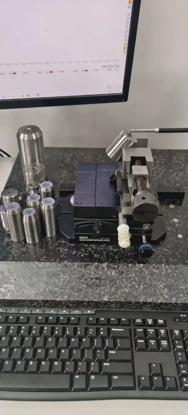
A misclassified zone is expensive to correct. Re-cutting a hardened cavity costs 2 to 4 weeks of schedule. The repair bill lands at 20 to 40% of the original tool value in typical cases. These parts also follow the same quality and warranty rules as other automotive components.
Sign the zone map off with the OEM before machining starts. Number every surface in the DFM drawing. Attach a finish class to each number. A lens face may carry an A1 callout at Ra 0.01 to 0.02 µm.
Its inner haze zone may sit at VDI 24 to 36. That one document later drives the polishing schedule, the gate plan and the inspection list. Cavity count is also fixed on this map. A 500 mm headlamp lens rarely runs more than 1x1. Mold base cost then runs 30 to 50% above a standard 2x2 frame.
Steel Selection for Lens Cavities: Polishability First
Clear lens cavities need steel that polishes to a mirror. S136 ESR is the default for optical work. Electro-slag remelting removes the inclusions that become pinholes on a polished face. After vacuum hardening it runs at 48 to 52 HRC typical. That hardness holds a mirror through 100,000 to 500,000 shot production runs.
NAK80 is the second common choice for lenses. It arrives pre-hardened at about 40 HRC typical. It skips the heat-treatment step and can shorten tooling lead time by 1 to 2 weeks. Use it for prototype lenses or validation runs under 50,000 shots. Softer steel dents and picks up orange peel faster at high volume.
Housing cavities follow a different logic. They need wear resistance and toughness, not a mirror. H13 or S136 hardened to 46 to 52 HRC typical is the standard answer. That applies to volumes above 100,000 parts per year. Glass-filled or flame-retardant housing resins push the choice toward the harder end.
| Mold zone | Typical steel | Typical hardness | Why it is chosen |
|---|---|---|---|
| Lens clear cavity | S136 ESR | 48 to 52 HRC | Polishes to SPI A1 without pinholes |
| Prototype lens cavity | NAK80 | 40 HRC pre-hardened | Short lead time, no heat treatment |
| Lamp housing cavity | H13 or S136 | 46 to 52 HRC | Wear and toughness at high volume |
| High-wear shut-off area | Hardened S136 | HRC 62 typical | Resists edge wear and flash |
← swipe to scroll →
Table note: Typical industry values for lighting tooling. Confirm steel and hardness with the mold maker at DFM stage, since run volume and resin decide the final grade.
Corrosion resistance matters on the lens side as well. Hot PC degrades slowly and releases acidic species near the steel. Stainless grades such as S136 resist that attack. Non-stainless steels pit under the same conditions after 50,000 to 100,000 shots typical. That pitting shows up first as haze on the polished optic.
Hardened steel also changes the machining plan. Cutting 48 to 52 HRC stock takes 20 to 30% longer than pre-hardened steel typical. Wire EDM handles the fine optic detail after hardening. Electrode count and EDM time go into the schedule at DFM stage.
Polishing to SPI A1 Without Surface Defects
SPI A1 is the baseline finish for a lens face. It measures Ra 0.01 to 0.02 µm. That sits below the wavelength of visible light. The surface neither scatters nor refracts light in a visible way.
Polishing removes real steel, so geometry drifts. Machine the cavity to within 0.02 to 0.05 mm of final size first. Hand polishing then takes out that stock. Skipping a grit step leaves deep scratches. Those scratches show as haze on the molded lens.
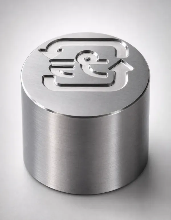
A typical schedule runs from 400 to 800 grit paper. Diamond paste follows at 6 µm, 3 µm and 1 µm. Change the polishing direction at every step. That crosses out the scratches from the previous pass.
EDM work on an optical face must be fully removed. Wire and sinker EDM leave a re-cast white layer of 0.01 to 0.03 mm typical. Polishing over that layer causes orange peel. It also leaves micro-cracks that open up in service. The full step sequence is in our mold polishing guide.
Inspect the mirror before assembly. Use a 5x to 10x loupe under angled light. Orange peel shows as a wavy reflection pattern. Check Ra on a witness coupon with a profilometer. Document the result before the cavity is bolted into the mold base.
Mirror cavities are handled like optics, not like steel. A single scrape from a tool ruins the face. Polishers and fitters use soft covers on bench fixtures. Re-polishing a scratched zone costs 1 to 2 days typical.
Controlling Optical Texture on the Inner Lens Wall
The inner wall of a modern lamp lens is rarely smooth. Pillow optics redirect light toward the legal beam pattern. These features are cut into the steel at 0.3 to 1.0 mm pitch. Where haze is wanted, the cavity gets a controlled etch. Typical textured surfaces land at Ra 0.4 to 1.6 µm.
Texture depth matters as much as the Ra number. A VDI 24 to 36 etch removes 0.03 to 0.06 mm of steel typical. Pre-texture machining must compensate for that loss. Otherwise the molded part grows thick in the textured zone.
Draft angle climbs with texture depth. The practical rule is 1 to 3 degrees for textured walls. Polished optics need only 0.5 to 1.0 degrees. Both values are typical industry guidance for lighting molds.
Specify texture by standard callout, never by verbal description. SPI, VDI and grain matching give a shared language between OEM and toolmaker. Approve the final choice on a molded coupon in the actual resin. A 48 to 52 HRC cavity also etches more evenly than soft steel. The full grade map is covered in our guide on how to specify mold texture.
Texture coupons cost little and save rework. Mold a coupon at the first trial. Compare it against the OEM master panel. Re-etching a full cavity costs 1 to 2 weeks typical. Coupons make that risk visible before production ramps.
Gate Placement That Hides Weld Lines
A weld line on a lens is an optical failure, not a cosmetic quirk. Two flow fronts meet and freeze into a visible seam. That seam scatters light and can push it out of the legal beam pattern. The fix is placement, not process. Gates land on non-optical faces, ribs, lugs or edges.
Small signal-lamp lenses take one or two side gates. Each gate feeds through a hidden lug on the part edge. Gate vestiges are held below 0.1 mm typical at the trim point.
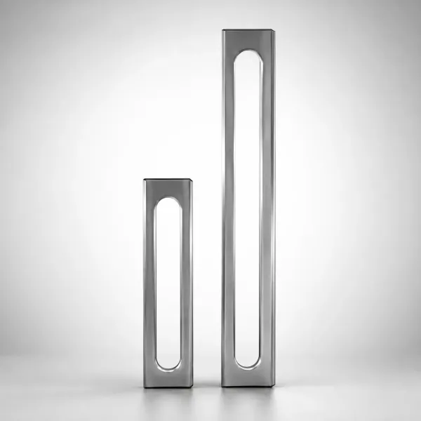
Large headlamp lenses use a film or fan gate. The gate runs across one edge of the part. The flow front then advances as a flat wave. The final weld line parks at the far edge. It can also finish behind an internal rib.
Runner balance matters more as cavity count climbs. A 4-cavity small-lamp mold needs natural balance. Equal flow keeps each lens optic identical. A hot runner suits 2x2 lens molds and saves 10 to 20% of cycle time typical.
Gate size follows the optic, not the wall thickness. A film gate land runs 0.5 to 1.0 mm thick typical. A tunnel gate bore runs 1.0 to 1.5 mm on small lamp lenses. Shear heating at the gate stays within the resin limit when those sizes are respected.
Resin preparation is the supporting input a mold cannot fix. Optical PC with moisture above 0.02% vents splay onto the mirror face. Drying at 120 °C for 4 hours typical is the standard answer. The full defect map for knit and flow lines is in our article on how to reduce weld lines.
Venting and Burn Risk on High-Gloss Cavities
Trapped air compresses as the melt front advances. It can reach temperatures that scorch the steel. On a polished face that scorch becomes a permanent brown mark. Repair means grinding below the damage. The mirror is then rebuilt with a 2 to 5 day re-polish.
PC is a medium-viscosity, low-moisture resin. Typical parting-line vents for PC run 0.01 to 0.02 mm deep. The vent land runs 3 to 5 mm before the relief slot. The relief slot opens to 0.3 to 0.5 mm depth typical. Deeper vents flash a glossy part, and shallower vents choke the air.
Ejector pins act as secondary vents. Pin clearance of 0.01 to 0.02 mm typical lets air escape. Weld lines trap air at their endpoints. Last-filled corners therefore get dedicated vents. Mold flow analysis shows where those corners sit before steel is cut.
Deep optic pockets trap air that parting-line vents cannot reach. Add core vents or porous steel in those pockets. Porous steel needs cleaning every 10,000 to 20,000 shots. A vacuum system is the last resort for thin lens walls.
Vent cleaning is also a maintenance task. Burns return when vents clog after 10,000 to 20,000 shots typical. Schedule vent checks inside the mold maintenance plan. Re-cutting a vent after a burn is a full cavity correction. Budget the same 2 to 4 weeks as any other rework.
Cooling Layout for Optical Stability and Short Cycles
Cooling dominates a lighting cycle. Typical lens cycles run 45 to 90 seconds. Cooling accounts for 60 to 75% of that total. Channel layout is therefore both a cycle lever and a quality lever.
The rule of thumb sets channel distance at 2 to 3 times the hole diameter from the cavity face. Channels of 8 to 12 mm sit 3 to 5 diameters apart, center to center.

Optical PC runs at 80 to 120 °C mold temperature typical. The mold must hold that temperature evenly. A spread above ±5 °C across the cavity causes differential shrinkage. That reads as warp and optical distortion on a flat lens.
Turbulent flow transfers heat far better than laminar flow. Target a Reynolds number above 4000 in each channel typical. Flow-rate checks belong in the mold trial checklist. Baffles and bubblers feed deep sections that straight drilling cannot reach.
Lens optics punish uneven cooling more than housings do. Warp of 0.1 mm on a 400 mm lens shows as measurable optical distortion typical. Cooling layout therefore gets the same DFM attention as gating. Both decisions are locked before steel is cut.
Balance the circuit by pressure drop, not by hole count. A starving cavity runs 3 to 5 °C cold. It shows different gloss and can add 10 to 20% to the cycle. Cooling design is the cheapest cycle-time investment before sampling starts.
Shrinkage, Draft and Tolerance Planning for Optics
Optical-grade PC shrinks 0.5 to 0.7% typical. Cavity steel is scaled by that factor before cutting. A 400 mm lens face grows 2.0 to 2.8 mm in the steel. Confirm flow-direction values on the resin data sheet. PC can shrink differently along and across flow.
Draft is the quiet geometry killer on optics. Polished optical faces run 0.5 to 1.0 degrees typical. That is the minimum that still releases a mirror finish. Textured walls need 1 to 3 degrees. Every rib, lug and housing wall gets its own callout on the zone map.
Warpage also follows gate count. A single-edge film gate on a 400 mm lens creates a bending moment from shrinkage. Two gates split the flow but add a weld line. Mold flow analysis weighs that trade before steel is cut.
Tolerance planning separates the optical print from the structural print. Key optical dimensions hold ±0.02 to ±0.05 mm typical. Those values are verified on molded parts. The steel itself is machined tighter than the part print. Molded tolerance always includes resin shrinkage scatter.
Clamp tonnage follows projected area. PC parts use 0.5 to 0.8 tonne per square centimeter typical. A large headlamp lens mold lands in the 150 to 300 tonne class. Small lamp molds run from 50 to 150 tonnes typical.
Tolerance charts also separate the steel print from the part print. Mold steel accuracy follows the tooling standard. Molded parts inherit resin scatter on top. A ±0.02 mm lens callout typically needs a steel feature at roughly one quarter of that value.
Housing and Light Guide Tooling Decisions
Lamp housings carry weld flanges, adhesive grooves and PCB standoffs. Their molds are usually simpler than the lens tool. Large housings run at 1x1 or 2x2 cavities. Small signal-lamp housings run at 4x4. Housing steel follows the cavity table above at 46 to 52 HRC typical.
Adhesive grooves need shut-off steel matched to the seal spec. Groove depth runs 0.5 to 1.0 mm typical. Wrong shut-off geometry causes adhesive bleed or a leaking lamp. Check groove walls against the housing draft before cutting.
Light guides are the third part family and the hardest on ejection. A lit light guide turns any ejector mark into a bright spot. Ejection therefore lands only on hidden ribs and lugs. Light-emitting faces never touch an ejector.
Film gates feed one end of the light guide. The flow front stays laminar along the part. Typical walls run 1.5 to 3.0 mm. Low and even stress keeps birefringence acceptable for even light output.
Undercuts bring slides and lifters into the design. Slide steels are nitrided or case-hardened to 50 to 58 HRC typical. That lets moving faces outlast the production run without galling. Standard components keep mid-run repairs fast. DieStrike ships ejector pins, core pins, mold bases and springs in 3 to 7 days.
Verification: CMM, OGP and Trial Protocol
Verify the steel before the mirror polish is signed off. A CMM report on the hardened cavity catches geometry errors early. Every optical feature at ±0.02 to ±0.05 mm is checked at that stage. Re-cutting is still possible while the insert is unfinished.
Touch probes cannot follow a 0.3 mm prism corner. Optical profiles go to a 2D vision system or an OGP contour projector. Pillow-optic facets are measured that way. CMM and OGP together cover the full optical print.
The first trial answers whether the part fills cleanly and whether the optic behaves. Dimensional checks on molded lenses confirm the real shrink factor. Haze, transmission and beam-pattern checks move to the customer photometry bench. Trials also expose venting, gate and polish defects that no drawing review predicts.
Run the protocol cavity by cavity. Each cavity is identified in the mold steel. First-article samples are kept per cavity. A later defect then traces to one insert. Typical sampling runs of 50 to 300 shots show the true dimensional scatter.
Keep a cavity ledger with the mold. Record steel grade, hardness and polish date per insert. Record EDM settings and texture batch numbers. A tool with a 2 to 5 week build time then carries a full repair history.
DFM and Selecting Your Mold Maker
Lighting molds punish the wrong supplier choice. Every correction touches a mirror surface. The DFM review is the quality gate. It confirms the zone map, gate placement and vent depths. Cooling, draft and tolerance feasibility are checked before steel is ordered.
A DFM answer that takes weeks is a risk signal. A 4 week recut can miss a vehicle launch window. DieStrike returns DFM feedback within 24 hours. That speed matters most when a lens program is already against the clock.
DieStrike is an IATF 16949 certified mold maker running 120+ machines. Mold dimensional accuracy runs ±0.005 mm. Mold component geometry holds ±0.002 mm. High-wear cavity zones are heat-treated to HRC 62. Injection mold lead times run 2 to 5 weeks from DFM approval.
The customer base includes automotive electronics and connector OEMs. TE Connectivity, Amphenol and Luxshare set that discipline bar. Their lighting modules and control units share the same dimensional standards. Ask any candidate three questions before cutting steel.
First, what S136 ESR or NAK80 polish trials has it run to SPI A1? Second, how does its DFM treat 0.01 to 0.02 mm vent callouts? Third, what CMM and OGP equipment verifies optical geometry? The answers separate a mirror-grade shop from a general toolhouse.
FAQ: Automotive Lighting Mold Design
Q1. Why can we not gate directly on the lens face?
A gate on an optical face leaves a vestige of 0.1 to 0.5 mm typical. It also leaves a stress ring that scatters light. It forces flow hesitation across the optic. Gates feed hidden lugs or edges instead. Trim the vestige below 0.1 mm typical at the trim point.
Q2. What steel gives the best mirror finish for a lens cavity?
S136 ESR hardened to 48 to 52 HRC typical polishes to SPI A1. The finish lands at Ra 0.01 to 0.02 µm with low pitting risk. NAK80 at about 40 HRC works for runs under 50,000 shots. It does not hold a mirror as long at high volume.
Q3. What vent depth works for PC optical parts?
Parting-line vents for PC run 0.01 to 0.02 mm deep typical. The land runs 3 to 5 mm. Deeper vents flash the glossy surface. Shallower vents trap air and burn the steel.
Q4. How many cavities should a headlamp lens mold have?
Large headlamp lenses typically run 1x1. Size and optical consistency drive that choice. Small signal lamps run 2x2 or 4x4. Fewer cavities mean fewer shrink and cooling signatures to match.
Q5. How do we verify an optical surface without destroying the lens?
Approve texture and finish on molded coupons first. Check geometry with CMM on the steel. Check molded lenses with OGP at ±0.02 to ±0.05 mm typical. Haze and transmission go to the customer photometry bench.
The Bottom Line
The mirror face decides whether a lighting mold succeeds. Polishable steel, hidden gates and 0.01 to 0.02 mm vents keep a Ra 0.01 µm surface alive through 500,000 shots. Balanced cooling protects the optical geometry. Send your lens or housing data through our contact page and get DFM feedback within 24 hours.
KEEP READING
Related Reading
Mold Polishing Guide: From Ra 3.2 to SPI A1
How a cavity moves from machined steel to a mirror finish: stone and paper sequences, diamond compounds, and the SPI grades from B1 to A1 that optical molds specify.
Read articleArticleHow to Specify Mold Texture: SPI, VDI and Grain Matching
Texture callouts control light scatter inside a lamp lens. This guide maps SPI and VDI grades to roughness values and shows how to verify them on coupons.
Read articleArticlePolycarbonate (PC) Injection Molding: Material Guide
Optical-grade PC shrinks 0.5 to 0.7% and needs 120 °C drying for 4 hours. The full guide covers grades, processing windows and mold-side requirements.
Read articleServiceMold Design & DFM
Send your lens or housing geometry for a DFM review with gate, vent, cooling and steel recommendations, returned within 24 hours.
Read articleNEXT STEP
Ready to Start Your Mold?
Send us your element dimensions or part numbers — our team responds within 24 hours with pricing and lead time.

Written by
Ray ChanMold Buyer's Guide Author · Precision Mold Manufacturing Specialist. Ray helps global importers, distributors and OEMs source factory-direct molds and mold parts.