
How to Reduce Weld Lines: Gate Placement and Tooling Fixes
Table of Contents
At 2:20 a.m. on a Friday night run, a quality technician pulled 3,200 connector housings from a 16-cavity tool. He flagged 840 for review. Tensile tests then broke 41 parts at the same spot, all along a hairline seam across a mounting boss. The seam measured just 0.03 mm deep, yet the boss carried only 52% of its design load. That seam was a weld line, and it looked cosmetic until it failed structural.
Weld lines, also called knit lines, are where two melt fronts meet, cool and fuse incompletely inside the cavity. They form around through-holes, cores, inserts, ribs and bosses, and at the far side of every flow obstruction. A weld line shows up as a faint surface seam or a V-notch 0.01 to 0.05 mm deep. The hidden cost is mechanical: a knit zone holds only part of the resin's full tensile strength.
This guide is the umbrella version of our per-resin articles. It ranks the fixes by payback: gate placement, overflow wells, mold temperature, venting and material change. Mold flow analysis predicts the knit before steel is cut. Figures are typical industry values; verify them on your resin data sheet and on your own knit test bars.
The Snapshot
- Unfilled amorphous resins such as ABS and PC keep 80-95% of tensile strength at a good knit; unfilled crystalline grades hold 70-90%.
- Glass-filled grades drop to 40-70% and LCP to 40-60%, because fibers sit parallel to the knit plane and never bridge it.
- A melt front temperature gap above 15-25 C at the meeting point makes a weak, visible knit likely; keep the gap under 10 C on structural parts.
- Raising mold temperature 10-30 C typically lifts knit strength 10-30%, and an overflow well 0.5-1.5 mm deep pushes the weak joint out of the part.
- Mold flow analysis locates the knit before steel, typically for 1-3% of tool cost, and removes 2-5 trial-shot iterations from the schedule.
Why Weld Lines Matter: Strength and Appearance
Judge a weld line by the job it does first. A faint seam on a painted A-surface rejects parts at 3-8% rates in cosmetic programs. Paint and plating amplify the notch into a visible crease. A knit on a structural boss, snap-fit arm or hinge carries load, and its failure is a field return, not a rework.
Visual severity and structural severity rarely line up. A 0.02 mm notch can be invisible to the eye and still cut tensile strength by 30-50% in a glass-filled grade. The reverse happens too: a frosty visible seam can sit on a resin that keeps 85-90% of strength, such as unfilled PC. Measure both appearance and load before you choose the fix.
The classic trap is the double weld. When melt splits around a through-hole, a boss or a core, the two fronts rejoin on the far side. They freeze two short knit lines, one per wall. Ribs and bosses near holes often carry both seams within 3-10 mm of the load path. Most double welds are found at first article, not at the DFM review.

Sort the defect before buying tooling changes. Ask three questions: does the line carry load, is it on a visible surface, and which resin family is running? A cosmetic-only knit on a non-loaded surface may need only a hotter mold or a vent. A loaded knit needs a gate move, an overflow well or a material change. Weld lines also travel with short shots, splay and hesitation marks; our guide on how to troubleshoot mold defects covers those companion symptoms.
How Weld Lines Form: Flow Fronts and Temperature
Two or more melt fronts reach the same point, and whichever arrives cooler and at lower pressure decides the bond. Fronts split at gates, cores, inserts, holes, bosses and sudden wall changes. A front that hesitates at a thin rib cools first and meets its partner late. The meeting angle matters too: a head-on collision freezes a notch, while an oblique merge knits more fully.
Temperature differential is the number to watch. Trial data show that fronts arriving more than 15-25 C apart in melt front temperature knit weakly. The seam shows on the surface too. Fronts within 10 C of each other fuse far better at the same cavity pressure. Gate and flow path design should keep both fronts hot and equal.
Time at temperature does the bonding. Polymer chains entangle only while the interface stays above the melt or glass-transition temperature. The skin of a 2 mm wall freezes in roughly 3-8 seconds at typical mold temperatures. A front that stalls early freezes a thicker, weaker knit. Air and gas trapped at the confluence also separate the fronts until pressure collapses the pocket.
Pressure packs the knit after the fronts touch. Low cavity pressure at the meeting point leaves a porous, notch-prone joint. That is why the last-filled corner and the far side of a long flow path produce the weakest welds. The fix list below moves the knit to a place where pressure and temperature arrive together.
Strength Loss by Material Family
Resin family sets the ceiling for knit strength. Unfilled amorphous resins give the best welds because long, mobile chains entangle across the seam. Crystalline resins give up more, and filled grades give up the most, because fibers orient along flow instead of bridging the knit. The gaps are large enough to redesign around once you know them.
| Material Family | Typical Retained Strength at a Good Knit | Why It Behaves This Way | Example Grades |
|---|---|---|---|
| Unfilled amorphous | 80-95% | Long chains entangle across the seam; no fibers to orient | ABS, PC, PS, PMMA |
| Unfilled crystalline | 70-90% | Weld zone may not re-crystallize as fully as the bulk | PA66, POM, PBT |
| Glass-fiber filled | 40-70% | Fibers align parallel to the knit and do not bridge it | PA66-GF30, PBT-GF30, POM-GF25 |
| LCP and highly filled | 40-60% | Rod-like molecules and fiber layers orient along flow | LCP, PPS+GF, PA46+GF |
← swipe to scroll →
Table: typical published weld line strength retention ranges. Actual values depend on wall thickness, gate design, process settings and knit quality; verify with a knit test bar before production.
Read the ranges with the word typical attached. A poorly vented, low-pressure knit in unfilled ABS can fall below 80%, while a well-packed knit in POM on a hot mold can exceed 90%. Glass-filled grades lose the most because the seam is held by matrix only, with no fibers crossing it. Ask your resin supplier for weld line data and run a tensile bar that reproduces the knit geometry.
Elongation collapses harder than strength at any knit. A filled grade may keep 50% of tensile strength yet drop to 10-20% of elongation at the seam. That matters for snap fits and living hinges. Impact-modified grades knit tougher because the rubber phase absorbs crack energy. If the part is structural, test impact and fatigue at the knit, not just tensile.
Gate Placement: The First Fix
Gate placement is the highest-impact fix because it decides where fronts meet. A single gate in the right spot can produce zero knit lines on many parts. Each additional gate shortens flow length but adds a knit line where fronts meet. The design task is to balance the two, not to maximize gate count.
Flow length sets the pressure budget. Typical maximum flow-to-wall ratios run 100-150:1 for unfilled amorphous resins and 60-100:1 for glass-filled grades. Beyond those, pressure climbs and the last-filled weld starves. Two gates can cut the effective flow length nearly in half and lower required injection pressure by 20-40%. Three or four gates on a large panel do the same, but each new meeting point is a new weld risk.
Move the gate, not the luck. Gate a boss from its base so melt fills it outward and no front wraps around it. Position the gate so fronts around a hole meet at an oblique angle on a non-critical wall instead of head-on at the load path. On cosmetic parts, hide the anticipated knit on the B-side or under a shadow line. Our guide on 7 gate design best practices covers gate type, size and position rules in full.
Gate count also interacts with cavity count. A 32-cavity tool still needs every cavity to fill identically; imbalance shifts knit positions from cavity to cavity and shot to shot. Balanced runners and identical gate geometry keep the knit in the same place every cycle, which is what makes overflow wells and vents workable. Fix runner balance before you blame the knit line.
Overflow Wells and Their Geometry
An overflow well is a small pocket cut in the steel at the knit location. It pushes the weak interface out of the part. The two fronts sweep through the weld zone and park the seam inside the well, which is trimmed as scrap. The knit that remains in the part forms at a higher temperature because the fronts keep moving while they join.
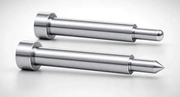
Geometry follows a simple recipe. Cut the well 0.5-1.5 mm deep at the knit, roughly the wall thickness or slightly more. Neck the opening with a land 0.5-1.0 mm wide so the part pulls clean at the trim point. Make the well diameter 2-3 times the local wall thickness so it fills, overflows and packs before freezing.
Place the well where the knit actually forms. That is usually the far side of a hole, boss or core, at the last-filled corner of a panel, or under a rib junction. Knits on moving surfaces such as snap arms may need the well cut in the moving half, with the trim action designed in. Wells add a trim step and a small flash risk, so reserve them for knits that carry load or sit on a Class-A surface.
Set expectations for the gain. A well-configured overflow well typically lifts knit strength 10-30% by moving the bond to a hotter, higher-pressure meeting point. It does not heal a cold knit caused by a 30 C front gap. Pair the well with mold temperature and venting work instead of using it alone.
Mold Temperature and Surface Heating
Hot steel keeps the meeting fronts molten longer, and molten chains entangle into a real bond. Raising mold temperature 10-30 C is the cheapest knit trial most molders never run. The gain shows fastest in crystalline and filled resins, where the weld zone re-crystallizes more completely against hot steel.

Typical mold temperature settings sit below the resin's optimal knit range. Unfilled amorphous parts run at 40-80 C mold temperature, PC at 80-120 C, and PA66 or PBT at 60-90 C. Reserve the top of each range for cosmetic or structural welds. LCP tools run the mold at 60-100 C with melt at 330-370 C. Stay inside the resin supplier's window; too hot slows the cycle and adds sink marks.
Surface heating goes further when the part earns it. Variotherm, or rapid heat cycle molding, heats the cavity surface to 120-180 C during fill, then cools before ejection. The extra equipment and longer cycle typically raise part cost 20-40%. It fits Class-A cosmetic panels and thin-wall structural parts where the knit cannot move. Start with a 10-30 C conventional rise before spending on variotherm.
Watch cycle time when you heat the mold. Every 10 C of mold temperature adds roughly 5-15% to cooling time on an unoptimized circuit, so pair the rise with cooling channel work. Measure part temperature at ejection and keep the rise inside the resin window. Mold temperature is a tuning knob, not a substitute for gate logic.
Venting at the Knit Line
Air and gas trapped at the confluence is a silent weld killer. As fronts close, trapped air compresses, heats and presses back, leaving a porous notch even when temperatures match. Venting at the knit lets the pocket escape so the fronts touch metal-to-metal under full pressure. Vent depth is a flash-versus-burn trade set by resin viscosity.
| Material Class | Typical Vent Depth (mm) | Venting Notes |
|---|---|---|
| PP, PE and low-viscosity flow grades | 0.01-0.03 | Deepest vents flash easily; keep the land short |
| Unfilled crystalline (PA66, POM, PBT) | 0.02-0.04 | Knit strength gains most from venting |
| Glass-filled grades (PA66-GF30, PBT-GF30) | 0.02-0.05 | Fiber content helps seal; less flash risk |
| Unfilled amorphous (ABS, PC, PMMA) | 0.03-0.06 | High viscosity tolerates deeper vents |
| LCP | 0.005-0.015 | Flashes at tiny clearances; vent via pins at the knit |
← swipe to scroll →
Table: typical parting-line vent depths by material class. Too shallow burns and starves the knit; too deep flashes. Verify each value against the resin data sheet.
Vent geometry is as important as depth. Keep the vent land 0.5-1.0 mm long, then open a relief 0.5-1.5 mm deep to atmosphere; a long land chokes the pocket. Space vents along the suspected knit every 5-15 mm where the parting line allows. A parting-line vent reaches the knit only when the knit sits on the parting plane.
Internal knits need internal vents. Knits around bosses, cores and inserts sit below the parting plane, so vent through ejector pins, inserts with machined clearances, or porous steel. A vented ejector pin placed 1-3 mm from the knit often clears the pocket that a parting-line vent cannot touch. Clean vents every 5,000-20,000 cycles; clogged vents are the top cause of weld lines that appear late in a production run.
Pair venting with the temperature fixes above. A vent clears trapped air; a hot mold keeps the fronts molten; together they move a weak knit toward the resin's retention ceiling. Full vent design rules, including land lengths and relief channel layout, are in our mold venting guide.
Predicting Weld Lines with Mold Flow Analysis
Mold flow analysis finds the knit before steel exists. The fill-pattern result plots every meeting point, the melt front temperature at each, and the meeting angle. The gate can then move in CAD instead of the toolroom. A DFM-stage analysis typically costs 1-3% of tool price and adds 3-7 days to the front of a program.
Read three outputs on the knit report. First, knit-line location and length across the part. Second, melt front temperature at each meeting point; flag every knit with a front gap above 15-25 C. Third, the meeting angle, because oblique merges knit better than head-on collisions.
Use the results to move the defect, then re-run. Relocate the gate, resize a rib, add a wall or shift the overflow well, and the knit plot moves with each change. Two or three analysis loops usually land the knit in a well or off the load path. Expect 2-5 fewer trial iterations on the press when the knit was predicted in advance.
Analysis has limits. It models fill well but approximates packing, shrinkage and fiber orientation, so treat its strength numbers as ranking tools rather than certificates. Gate a test bar with the same knit and verify strength before production. Our mold flow analysis guide explains when simulation pays and how to specify the study.
When Material Change Is the Real Fix
Sometimes the geometry wins and the resin has to change. A knit that cannot move off a load path, in a grade whose retention ceiling is 40-50%, fails no matter how well the tool vents. Material substitution is the last fix because it changes the whole part story: strength, cost, shrinkage and cycle time.
Unfilled and impact-modified grades knit stronger than filled ones. PA66-GF30 keeps roughly 40-70% of tensile strength at a knit, with a 9,000-10,000 MPa modulus. Impact-modified unfilled PA66 keeps 80-90% at the knit, yet its modulus drops to 2,800-3,200 MPa. If stiffness drives the design, compare the knit zone gain against the modulus loss before switching.
Mineral and glass-bead fillers behave better than fiber at a knit. Beads and platelets do not align along the weld plane the way fibers do, so retention sits closer to the unfilled range in many grades. Fiber length changes the picture too: short-glass grades knit better than long-glass versions at the same loading. Ask suppliers for knit retention data before you commit a structural grade.
LCP deserves its own warning. Rod-like molecules orient along flow, so a head-on knit in LCP retains roughly 40-60% of strength. The seam is brittle too. Thin-wall connectors live with this by gating to avoid flow-around-core welds. They also run maximum melt and mold temperature.
The LCP material guide details the melt, tool and gate settings that hold its knits at the top of the range. When an LCP knit still fails, the answer is usually geometry, not another LCP grade. The PBT and POM material guides carry the same per-resin detail for their families.
FAQ: Reducing Weld Lines
Q1. Where do weld lines most often show up on a molded part?
The far side of through-holes, cores, inserts and bosses, where the melt splits and rejoins, plus any last-filled corner of a long flow path. Around a hole the result is a classic double weld, two short seams 3-10 mm apart, one on each wall. Multiple gates add a meeting line at the balance point between them.
Q2. Can a weld line be removed completely?
Yes, when geometry allows. A single gate with no flow split around a core produces zero knit lines. Relocating the gate to one side of a hole turns a head-on weld into a stronger oblique merge. When the knit cannot be removed, an overflow well 0.5-1.5 mm deep moves the weak seam out of the part so it can be trimmed.
Q3. How much strength does the part really lose at a knit?
It depends on the resin family: unfilled amorphous grades keep 80-95% at a good knit, unfilled crystalline 70-90%, glass-filled 40-70%, and LCP 40-60%. Elongation falls harder, often to 10-20% of the base value at the seam. Verify with a tensile bar that reproduces the knit rather than trusting the range.
Q4. Does raising mold temperature fix weak knits in LCP and other hard cases?
Partially. A 10-30 C rise plus maximum melt temperature helps LCP knits reach the top of their range. LCP still sits at 40-60% retention at best. Gate the part so fronts meet obliquely and vent at the knit with shallow 0.005-0.015 mm vents. Reserve material change or geometry revision for seams that still fail.
Q5. How do I prove a knit is acceptable before production?
Gate a test bar with the same knit geometry and mold it at production settings. Pull it in tension and compare against an unknit bar. Confirm the retention ratio meets the design target, commonly 60-70% minimum on structural connector housings, and check the fracture surface for a clean bond. Repeat after any process or tooling change.
The Bottom Line
Fix weld lines in order. Place gates so fronts meet hot and oblique, then park the remaining knit in an overflow well 0.5-1.5 mm deep. Raise mold temperature 10-30 C and vent the meeting point. Predict the whole scheme with mold flow analysis before steel. Unfilled amorphous resins can hold 80-95% of strength at a well-made knit; glass-filled and LCP grades need the geometry to do the work for them.
Verify every fix with a knit test bar, because published retention ranges depend on wall thickness, gate, fiber content and process. A tensile bar molded at production settings beats any table. Document the knit location on the mold drawing so trials, repairs and future changes respect it.
DieStrike builds molds under IATF 16949 with 120+ machines and hardened cavity steel at HRC 62. Standard geometry holds ±0.005 mm and precision geometry ±0.002 mm, with molds in 2-5 weeks and standard components in 3-7 days. Connector OEMs including TE Connectivity, Amphenol and Luxshare run our tools. Knit lines are reviewed at the DFM gate with mold flow, not discovered at first article. Send the part file and the load case, and we will tell you where the knit lands before we cut steel.
KEEP READING
Related Reading
7 Gate Design Best Practices for Balanced Filling
Mold maker's 7 gate design rules for balanced multi-cavity filling: gate depth 50-80% of wall thickness, land 0.5-1.
Read articleArticleMold Flow Analysis: When It Pays in Mold Design
Mold flow analysis predicts knit-line position, meeting temperature and fill pressure before steel is cut; analysis costs 1-3% of tool price and removes 2-5
Read articleArticleMold Venting: Depth, Location and Design Rules
Mold venting at the knit line clears trapped air so fronts meet under full pressure: vent depths run 0.01-0.06 mm by material, with a land 0.5-1.
Read articleArticleHow to Troubleshoot Mold Defects: 9 Common Causes
Nine common mold defects from short shots to splay share root causes with weak knits: hesitation, low pressure and trapped gas behind 70-80% of fai
Read articleNEXT STEP
Ready to Start Your Mold?
Send us your element dimensions or part numbers — our team responds within 24 hours with pricing and lead time.

Written by
Ray ChanMold Buyer's Guide Author · Precision Mold Manufacturing Specialist. Ray helps global importers, distributors and OEMs source factory-direct molds and mold parts.