
How to Design Blanking Dies: Clearance, Strippers and Scrap
Table of Contents
A 2 mm mild steel bracket ran at 12 percent clearance per side and produced a 0.30 mm burr against a 0.10 mm print limit. The deburring cell added 9 seconds to every part, and the 40,000 piece order absorbed close to 100 hours of extra labour. The edges were not worn and the tonnage was inside the rating; the clearance was wrong from the first drawing. This article covers the working design of a blanking die: clearance by material, punch and die sizing, stripper choice, slug control, layout and the burr budget.
The figures below are typical values for sheet from 0.5 to 6 mm and need checking against the material certificate.
The Snapshot
- Clearance drives the burr. A 5 to 10 percent clearance per side on mild steel and 8 to 12 percent on stainless and AHSS holds the burr near 5 percent of sheet thickness, which is 0.10 mm on a 2 mm sheet against 0.30 mm at 12 percent per side.
- Force runs 0.6 to 0.8 of ultimate tensile strength. A 300 mm blank perimeter in 2 mm steel at 320 MPa needs 144 kN of shear force, plus 10 to 20 percent more for the stripper.
- Punch shear cuts the peak 20 to 30 percent. A 1.5 to 5 degree shear angle across the punch face on a 2 mm sheet spreads the load over a longer stroke and lowers the shock on the press.
- Hardened edges hold 100,000 to 1,000,000 hits. D2 or A2 at HRC 58 to 62 covers that window in mild steel, while PM-HSS and carbide take over above 1 million hits or on stainless.
How the Cut Works: Clearance, Break and Rollover
A sheared edge is four zones stacked through 2 mm of steel. Rollover appears where the punch first presses into the surface. The burnish band is the smooth wall the punch shears away. The fracture zone is the rough grain where the two cracks run and meet. The burr is the thin lip of material left at the die side of the cut.
Clearance sets where those two cracks meet. At the right clearance, the crack running down from the punch edge and the crack running up from the die edge travel toward each other and join. The fracture zone stays narrow, rollover stays under 30 percent of thickness, and the burr lands near 5 percent of thickness.
Open the clearance too far and the cracks miss. The bridge of material between them has to tear in tension, which widens the fracture zone, drives rollover past 30 percent of thickness and pushes the burr toward 15 percent of thickness. On a 2 mm sheet that is 0.30 mm of burr against the 0.10 mm a typical print allows.

Tighten the clearance too far and the edge looks clean while the tool pays for it. A cut under 4 percent per side on 2 mm mild steel raises the temperature at the punch face and wears a sharp edge out in 20,000 to 40,000 hits instead of 100,000.
A part that needs a 90 percent shear face without a secondary machining step goes to fine blanking instead, where a V-ring and counter pressure replace clearance control.
Clearance Numbers by Material and Thickness
Clearance is written as a percentage of sheet thickness per side, because that is the number the die is cut to. A 2 mm mild steel blank at 7 percent per side carries 0.14 mm per side, which is 0.28 mm between punch and die.
Blanking and piercing put the clearance on opposite components, and mixing the two is a common reason a new die runs out of print. In blanking the part is the slug, so the die opening holds the part size and the punch is cut smaller by twice the clearance. In piercing the hole is the part feature, so the punch holds the hole size and the die opening is cut larger.

| Material | Tensile strength | Clearance per side | Notes |
|---|---|---|---|
| Low carbon steel, 1 to 3 mm | 320 to 400 MPa | 5 to 7 percent of thickness | Burr near 5 percent of thickness with D2 edges at HRC 58 to 62 |
| Low carbon steel, above 3 mm | 320 to 400 MPa | 6 to 9 percent of thickness | Thicker sheet tolerates more clearance before the burr grows |
| Stainless 304 and 430 | 520 to 700 MPa | 8 to 12 percent of thickness | Work hardens at the edge; PM-HSS or carbide above 1 million hits |
| AHSS DP590 and DP780 | 590 to 800 MPa | 8 to 11 percent of thickness | Wider clearance protects the punch edge from the shear load |
| AHSS DP980 and above | 980 to 1,200 MPa | 9 to 12 percent of thickness | Add punch shear and a die protection sensor on each blank station |
| Aluminium 5052 and 6061 | 230 to 310 MPa | 6 to 10 percent of thickness | Soft sheet smears; polish the die face to stop pick-up and galling |
| Zinc coated and galvanized | 320 to 420 MPa | 6 to 8 percent of thickness | Coating flakes at tight clearance; add 1 percent and lubricate for the coating |
← swipe to scroll →
Table note: clearance bands are typical shop values for a single stroke blanking die. Confirm the tensile strength and the coating on the material certificate, then set the final clearance against a physical tryout strip.
The band matters more than the exact value, and it narrows as the edge wears. A die cut at 6 percent and a die cut at 8 percent both hold a 0.10 mm burr on 2 mm mild steel, while a die at 14 percent will not.
Shear Force, Stripper Load and Press Tonnage
Shear force is the cut perimeter times sheet thickness times ultimate tensile strength, scaled by a shear factor of 0.6 to 0.8. That factor exists because fracture starts after 0.6 to 0.8 mm of penetration in a 2 mm sheet.
Take a 300 mm blank perimeter in 2 mm mild steel at 320 MPa. The force is 300 x 2 x 320 x 0.75, which is 144 kN, or about 14.7 metric tonnes. Add a stripper load of 10 to 20 percent and the blank station demands 158 to 173 kN at the bottom of the stroke.

Choose the press so the peak shear force sits at 60 to 70 percent of rated capacity. That margin covers friction in the slides, the strip feeder and the wear of the next 500,000 hits.
Check stroke energy as well as tonnage. The 144 kN blank in 2 mm steel consumes 90 to 115 J per stroke, and a press inside its tonnage rating can still stall on a flywheel sized for a shallow coining job.
A shear angle across the punch face lowers the peak load 20 to 30 percent. Grind 1.5 to 5 degrees on the punch face for sheet up to 3 mm, and the cut starts at one end instead of hitting the full perimeter at once. The energy per stroke stays close to the same, so the saving is in peak force and press shock. The full arithmetic sits in the article on calculating press tonnage for stamping dies.
Punch and Die Materials, Hardness and Plate Thickness
D2 and A2 cover most blanking work at HRC 58 to 62. That window holds a sharp edge for 100,000 to 1,000,000 hits in mild sheet. At DieStrike, hardened die and punch edges are heat treated to a maximum of HRC 62.
Move above 1 million hits, or onto stainless and AHSS, and the grade changes. PM-HSS and carbide edges resist the abrasive wear those materials drive, at 2 to 4 times the edge cost. Grade-by-grade selection and the hardness trade-offs are set out in the article on selecting stamping die steel.
Die plate thickness runs 25 to 40 mm for a 2 mm sheet, which is 12 to 20 times material thickness. A backing plate of 20 to 30 mm carries the bending load, and corner inserts take the wear at the strip entry.
Every cutting opening needs a short straight land and then relief. Hold a 3 to 5 mm parallel land below the die face, then open the slug hole 0.5 to 1 degree so slugs fall free. A land longer than 5 mm grips the slug, and a die with no relief has to be stripped apart to clear a jam.
Stripper Design: Solid, Urethane and Preload
The stripper does two jobs. It holds the sheet flat against the die face while the punch cuts, and it pulls the strip off the punch on the upstroke without dragging the blank out of position.
A solid stripper on a fixed stop is the stable answer for sheet from 1.5 mm upward. Set the stripper face 1.5 to 2 percent of sheet thickness below the strip line, so the sheet is clamped before the punch enters the material and cannot ride up the punch face.
Spring and urethane strippers suit high speed and thin gauge work, where a solid plate would be too heavy to cycle. Urethane pads carry 5 to 15 percent of the blank force and return fast; size the pad so it is compressed 15 to 25 percent of its free height at the bottom of the stroke, and the force curve stays flat across the last 3 to 5 mm of travel.
Budget the force before choosing hardware. Stripper force runs 10 to 20 percent of the shear force, so a 144 kN blank needs a 14 to 29 kN stripper, which on a 4 spring pack is 4 to 7 kN per spring at the working deflection. Size the springs at the compressed length, never at free length.
Run 0.02 to 0.05 mm between the punch and the stripper bore, and hold the punch on a shoulder so bore wear cannot walk the punch off centre.
Slug Pulling, Slug Escape and Scrap Chutes
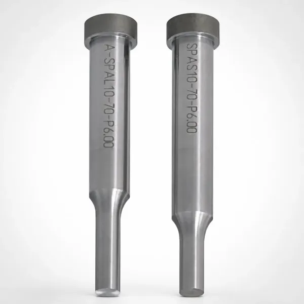
A pulled slug rides up the punch and lands on the strip. The next hit coins it into the die face and takes out a punch edge, and one slug can turn a 10 minute stop into a full die repair.
Five causes cover most events. Clearance more than 3 percent per side above nominal, a die land longer than 5 mm, a flat and well oiled punch face, a die opening that has bell-mouthed from wear, and a slug that springs against the punch wall as it releases.
Fix the geometry before adding hardware. Taper the slug hole 0.5 to 1 degree below a 3 to 5 mm land, break the punch face with a shallow crown or a 0.2 to 0.5 mm bevel on one edge, and keep the punch face at 0.4 to 0.8 micrometre Ra so oil cannot hold a slug by surface tension.
Scrap has to leave the die as fast as it arrives. Size the slug chute at 1.5 to 2 times the blank section so two slugs can never bridge it, and slope side exits at 15 to 30 degrees so offcuts slide out instead of stacking under the die block. A chute that is 1 to 1.2 times the blank section will block within a shift.
Then add a positive device as a second line. A spring loaded slug ejector inside the punch, an air blast at 0.3 to 0.5 MPa on slug exit, or an anti-pull insert on a heavy blank all work.
Blank Layout, Web Width and Registration
Layout decides how much of the coil becomes a part. Carry a web of 1.5 to 2.5 times sheet thickness between blanks and the same bridge at the coil edge, which on a 2 mm sheet is a 3 to 5 mm bridge that must not shear thin.
Nest wherever the geometry allows. A round blank nested on a 0.5 to 1.0 times thickness offset lifts material use 8 to 15 percent against a straight row.
Match the coil width to the layout instead of forcing the layout onto a stock coil. A 300 mm coil carrying two 120 mm blanks and three 4 mm bridges puts 84 percent of the strip into parts, against 83 percent for the same blank on a 155 mm coil.
Registration is a clearance problem, not a sensing problem. Pilots locate the strip through pierced holes at 0.02 to 0.05 mm per side, and a two step pilot enters on a taper and then locates on a straight shank for high speed feed. Set the pilot diameter at hole size minus 0.04 to 0.10 mm and make sure the pilot is fully engaged before the blank punch touches the strip. Station sequence and carrier design belong to the article on designing a progressive die layout.
The Burr and Rollover Budget
A blanking print should state the burr side and the burr height, because the tool has to be built around both. Most prints allow 5 percent of sheet thickness, which is 0.10 mm on a 2 mm sheet, and 10 to 15 percent where the edge will be welded, painted or covered by a gasket.
The burr forms on the die side of the cut, opposite the punch entry, so the direction is fixed by how the tool is built rather than by how it is set. If the drawing calls for the burr up, drive the punch down or invert the strip; never leave the burr side to the operator's judgement at the press.
Rollover is the other half of the budget. Expect 20 to 30 percent of thickness of rollover on a correctly cleared cut, which is 0.4 to 0.6 mm on 2 mm sheet, alongside a burnish band of 40 to 50 percent and a fracture zone of 20 to 30 percent. A print that allows 0.1 mm of rollover on a 2 mm part is asking for a different process.
Resharpen on the burr, not on the calendar. A D2 edge in mild steel holds 100,000 to 200,000 hits before the entry radius passes 0.20 mm, while stainless and AHSS grades reach the same limit in 30,000 to 80,000 hits. A die that runs past the limit cuts a 0.20 mm burr and needs 0.3 to 0.5 mm ground off the face to recover.
Compound, Progressive and Fine Blanking Compared
The same flat part can be cut three ways, and the route is decided by tolerance, volume and edge quality rather than by shop habit. Each route changes the clearance, the press and the tool cost together.
A compound die cuts the full profile in one stroke and drops the blank through the bed. It holds the best hole to edge relationship and the best flatness, and it suits a flat part with a moderate annual volume where the tool budget is tight.

| Item | Compound die | Progressive die | Fine blanking |
|---|---|---|---|
| Clearance per side | 6 to 10 percent of thickness | 6 to 10 percent of thickness | 0.5 to 1 percent of thickness |
| Edge and burr | Burr near 5 percent of thickness | Burr near 5 percent of thickness | 90 percent shear face, burr under 0.02 mm |
| Flatness on a 150 mm part | Best of the three routes | 0.1 to 0.2 mm in the strip | 0.05 mm with counter force |
| Press | Standard mechanical press | Standard press at 60 to 400 SPM | Triple action hydraulic, 2 to 3 times tonnage |
| Tool cost for one profile | Lowest | Higher, adds stations and carrier | Highest, adds V-ring and counter pad |
| Hits between sharpenings | 100,000 to 200,000 in mild steel | 100,000 to 200,000 in mild steel | 30,000 to 80,000 on a 4 mm part |
← swipe to scroll →
Table note: route comparison at typical shop values for carbon steel. Confirm tonnage, sheet range and flatness against the press specification and the part print before the tool route is fixed.
A progressive die spreads the work across stations, carries the strip on a skeleton, and cuts the blank free at the last station. It earns its cost above roughly 200,000 parts a year, runs 60 to 400 strokes per minute, and absorbs a pierce, a form or a lance without a second operation.
Fine blanking buys a cut face that needs no secondary machining. It cuts at 0.5 to 1 percent clearance per side with a V-ring stinger of 0.5 to 0.8 mm width and a counterforce of 30 to 50 percent of the shear force, on a triple action press that carries 2 to 3 times the conventional tonnage.
Tolerances, Inspection and Die Trial
Cut the die opening to plus or minus 0.005 mm and hold the punch to die clearance to plus or minus 0.01 mm on the pair. At DieStrike, EDM and jig grinding work runs to plus or minus 0.002 mm, which is what makes an 8 percent clearance repeatable across every station of a multi-station die.
Inspect the parts before the die is assembled. CMM the die opening, the punch profile, the pilot diameters and the stripper face, and check punch to die parallelism at 0.01 mm over 300 mm. A punch that is tilted by 0.02 mm cuts one side of the blank at 5 percent clearance and the other side at 12 percent, and the burr appears on one edge only.
Acceptance numbers worth writing into the purchase order: burr under 5 percent of thickness, blank dimensions inside print on the first article, no slug pulling across 1,000 consecutive hits, slug and scrap clear of the die at 60 strokes per minute, and a Cpk of 1.33 or better on the critical dimensions from a 50 part study.
DieStrike builds blanking, piercing, compound and progressive dies to IATF 16949, with 120+ machines and tier-1 references that include TE, Amphenol, Luxshare and Dongshan. Standard components ship in 3 to 7 days, complete tool lead times run 2 to 5 weeks, and hardened edges go to HRC 62 max. Send the part print, the material grade and the annual volume to the stamping die manufacturing team and we will return a clearance and tonnage plan before the die steel is ordered.
Blanking Die Design FAQ
Q1. How do I turn a clearance percentage into punch and die sizes?
For blanking, set the die opening at the part size and cut the punch smaller by twice the clearance. A 2 mm mild steel part at 7 percent per side needs 0.14 mm per side, so the punch is 0.28 mm under the die opening. For piercing, reverse it: the punch holds the hole size and the die opening is cut 0.28 mm larger.
Q2. What stops slug pulling in a blanking die?
Clearance under 3 percent above nominal, a die land of 3 to 5 mm, a 0.5 to 1 degree taper below the land, and a punch face at 0.4 to 0.8 micrometre Ra. Add a spring slug ejector, an air blast at 0.3 to 0.5 MPa or an anti-pull insert on heavy blanks, then confirm with a die protection sensor.
Q3. How much stripper force does the die need?
Budget 10 to 20 percent of the shear force, which is 14 to 29 kN on a 144 kN blank. Urethane pads cover the lower end at 5 to 15 percent of blank force for thin gauge work. Size springs at the compressed length, because a spring pack loses 20 to 30 percent of its force over 1 million cycles.
Q4. What burr height is acceptable on a blanked edge?
Under 5 percent of sheet thickness, which is 0.10 mm on 2 mm steel and 0.25 mm on 5 mm steel. Welded, painted or gasketed edges often accept 10 to 15 percent. Measure five parts every 5,000 hits and resharpen before the entry radius passes 0.20 mm.
The Bottom Line
A blanking die is four numbers: clearance per side of 5 to 12 percent of thickness, shear force plus a 10 to 20 percent stripper load, an edge at HRC 58 to 62 on a 25 to 40 mm plate, and a burr budget of 5 percent of thickness. Set them in the drawing and the tool runs from the first strip. Miss them and no press setting recovers the edge.
DieStrike builds blanking, piercing, compound and progressive dies to IATF 16949 with plus or minus 0.005 mm die accuracy, plus or minus 0.002 mm on EDM and jig grinding, and HRC 62 maximum edge hardness. Standard components ship in 3 to 7 days and complete tools in 2 to 5 weeks.
KEEP READING
Related Reading
How to Calculate Press Tonnage for Stamping Dies
Perimeter, thickness, shear strength and the safety margin that keeps a die off the press frame stops.
Read articleArticleHow to Prevent Stamping Burr: Clearance, Wear and Set-Up
Which variables raise burr height, and the inspection numbers that tell you when to resharpen.
Read articleArticleHow to Design Stamping Die Strippers
Solid, spring and urethane strippers, plate clearance and the force budget behind each choice.
Read articleServiceStamping Die Manufacturing
IATF 16949 die building with clearance and tonnage planning, HRC 62 max edges and 2 to 5 week lead times.
Read articleNEXT STEP
Ready to Start Your Mold?
Send us your element dimensions or part numbers — our team responds within 24 hours with pricing and lead time.

Written by
Ray ChanMold Buyer's Guide Author · Precision Mold Manufacturing Specialist. Ray helps global importers, distributors and OEMs source factory-direct molds and mold parts.