
Stamping Die Strippers: Pressure Pads and Stripper Plates
Table of Contents
A 12-station progressive die running 1.2 mm cold-rolled steel lifted its stripper plate 0.06 mm off the strip on the second shift. Four coil springs with no preload could not hold the 320 mm plate flat between stations. The strip rose with the punches instead of being pressed off them. By part 8,400 a slug had jammed and two 6 mm pilots sheared. The press then stood idle for 5 hours while the plate and the punch block were rebuilt.
A stripper is not a cover plate. It clamps the strip flat against the die face and presses the part and skeleton off the punch after every stroke. It also guides the slender punches that cannot stand on their own. Force, travel and clearance decide whether it does those three jobs or fights them.
This guide works through the numbers behind that job. It covers stripping force as a share of blanking force, spring selection and preload, travel and guidance, punch clearance and plate stiffness. Punch support, strip control, pressure pads in draw dies, galling, marking defects and spring replacement intervals follow. All figures are typical published or shop values for sheet metal from 0.4 mm to 4 mm. Each one still needs checking against the strip grade, the press and the drawing before a die is cut.
The Snapshot
- Stripping force at 3 to 10 percent of blanking force. A 240 mm cut perimeter in 1.2 mm cold-rolled steel takes roughly 86 kN of blanking force, so the stripper needs 2.6 to 8.6 kN at full travel.
- Preload at 15 to 20 percent of travel. A spring that only touches the plate at top dead center lets the strip lift 0.05 to 0.15 mm and pulls parts off station.
- Punch clearance of 0.01 to 0.03 mm per side. The stripper bore runs tighter than the die clearance, which sits at 0.06 to 0.12 mm per side on 1.2 mm steel.
- Plate flatness within 0.02 mm. Bowing above 0.05 mm across a 300 mm plate marks the strip and cuts punch life by 30 to 50 percent.
Why Strippers Decide Die Performance
A stripper does three jobs at once: clamp, strip and guide. In a progressive die running 200 to 600 strokes per minute, all three happen inside 100 milliseconds. There is no time for a plate to settle, and no second chance if it lifts.
Stripping is the job that fails in service. Friction between punch and sheet can drag the strip 0.05 to 0.30 mm off station as the punch withdraws. That drag is worst on stainless, aluminium and coated steels, where dry contact can pull 8 to 20 percent of the blanking force upward. Anything the stripper does not hold flat rises with the punch and then falls back a little off position.
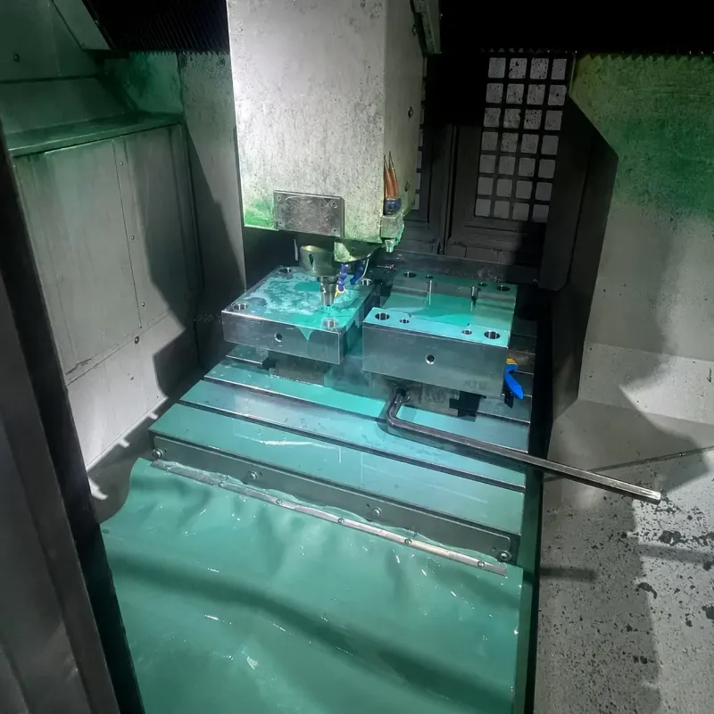
Punch support is the second job, and it is the one buyers pay for later. A 2 mm round punch in 3 mm stainless behaves like a spring: it bends before it breaks. The stripper bore is the only lateral support that punch gets between strokes. Clearance in that bore decides whether it cuts straight or deflects 0.05 mm and tears the hole edge.
All three failures share one cost structure. Die maintenance rises, strip quality drops, and the die comes off the press for unplanned work in the middle of a run. Most of that is avoidable at the drawing stage with four numbers: 3 to 10 percent, 15 to 20 percent, 0.01 to 0.03 mm and 0.02 mm.
How Stripping Force Is Calculated
Start from blanking force, because stripping force is defined as a share of it. Blanking force equals cut perimeter times sheet thickness times shear strength: F = P x t x tau. For a bracket with 240 mm of cut edge in 1.2 mm cold-rolled steel at 300 MPa shear, that is 86 kN.
Stripping force is then taken as 3 to 10 percent of that number, which gives 2.6 to 8.6 kN for the same bracket. Where the share lands depends on thickness, material and how much of the strip the punches grip. Thin and soft sheets take the high end because the punch embeds less and releases less cleanly.
| Sheet and material | Typical die clearance per side | Stripping force share | What drives it |
|---|---|---|---|
| 0.5 to 0.8 mm cold-rolled steel | 0.03 to 0.05 mm | 7 to 10 percent | Low punch embedment, high friction per unit of thickness |
| 1.0 to 1.5 mm cold-rolled steel | 0.06 to 0.12 mm | 5 to 8 percent | Baseline case for most progressive dies |
| 2.0 to 3.0 mm hot-rolled or HSLA | 0.15 to 0.30 mm | 3 to 6 percent | Heavier shear load, thicker punch shank, more grip |
| 0.8 to 1.5 mm aluminium | 0.05 to 0.09 mm | 8 to 12 percent | Soft metal smears and clings to the punch face |
| 0.8 to 2.0 mm stainless 304 or 430 | 0.08 to 0.15 mm | 7 to 11 percent | Work hardening and galling raise withdrawal friction |
← swipe to scroll →
Table note: clearance and force shares are typical values for single-stroke blanking in a guided die. Confirm against the strip grade certificate and the shear strength used in the tonnage calculation, and record both in the die file.
Then add a safety factor. Size the spring package for 1.5 to 2.0 times the calculated stripping force. Springs lose 10 to 20 percent of rated force over the first 250,000 strokes, and galling raises withdrawal friction as a die wears. A stripper sized exactly at the calculated number works well for a week and fails on the second.
Spring Selection and Preload
Three spring types dominate stamping dies, and each has a band where it is the right answer. Coil die springs in chromium-silicon wire handle most applications up to about 10 kN per spring. Nitrogen gas springs deliver constant force from very little space and hold their force to within 5 percent over the stroke. Urethane springs are cheap, but their force rises steeply with deflection and they sag above 60 degrees C.
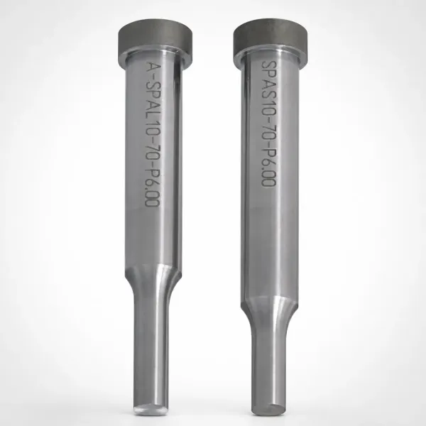
Preload is the number shops skip. A coil spring should start the stroke already compressed by 15 to 20 percent of its working travel. On an 8 mm stripper travel that means 1.2 to 1.6 mm of preload. Roughly 15 to 25 percent of the spring force is applied before the punch touches the sheet. Without it, the plate rattles, the strip lifts, and the springs see an impact load instead of a gradual one.
Stay inside the deflection limit. A coil die spring rated for 30 to 40 percent of free length as maximum travel should be designed to 20 to 25 percent for a long life. Running a spring at its catalog maximum is the fastest way to shorten free length by 1 to 2 mm. At that point the stripper stops holding the strip at all.
Set the preload with shims or a shoulder screw, not with a spacer cut in the shop. Then write the installed height on the drawing. A package that is 2 mm short on installed height will still assemble and strip parts for a few thousand strokes before marking defects appear.
Gas springs belong on high-force, low-space jobs: heavy trim pads, draw die pressure pads, and thick-sheet blanking where four coil springs cannot fit in the pocket. They cost 5 to 10 times a coil spring and need a charge check, but they hold force for 500,000 to 2,000,000 strokes. That saves 30 to 50 percent of the pocket space. That space often decides the plate layout on a crowded upper shoe.
Stripper Travel and Guidance
Stripper travel is set by the material, not by the spring catalog. The plate has to clear the strip by enough for the feed to advance without dragging. It also has to stay engaged long enough to hold the strip flat through the cut. A working rule is sheet thickness plus 3 to 6 mm of clearance. A 1.2 mm strip then needs 5 to 8 mm of travel, and a 3 mm strip needs 8 to 12 mm.
Feed height drives the same number from the other side. If the strip has to lift 4 mm to clear a pilot or a lifter, a stripper with 3 mm of travel will drag the strip on every stroke. That drag shows up as scratched stock, a jammed feed and a 0.1 to 0.3 mm loss of station accuracy within a single shift.
Guide the plate on shoulder screws or on dedicated guide pins, never on the springs. Four shoulder screws of 12 to 16 mm diameter on a 300 to 500 mm plate keep it parallel within 0.02 mm. Add hardened bushings in the stripper plate when the die runs above 300 strokes per minute. A shoulder screw alone is a locating device, not a bearing.
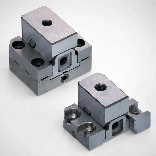
Long travel without guidance is a defect generator. A plate that tilts 0.10 mm releases one corner of the strip before the other. The punches on that corner then pull the sheet upward while their neighbours still clamp it. The result is a bent 3 mm punch and always at the station where the tilt is worst.
Clearance Against the Punch: The 0.01 to 0.03 mm Rule
The stripper bore is a sliding fit on the punch, and its clearance is the tightest tolerance in the die. Typical stripper clearance runs 0.01 to 0.03 mm per side for punch diameters above 3 mm, and 0.005 to 0.015 mm per side for punches under 3 mm. It must stay tighter than the die clearance, which runs 5 to 10 percent of sheet thickness per side.
Clearance works both ways. Too loose and the punch bends inside the bore, guides poorly and wears a bell mouth that grows 0.01 mm per 100,000 strokes. Too tight and the bore grips the punch, wipes off lubricant and starts to gall the shank. Galling on a punch shank then transfers to the bore, and the pair seize at the next break in the run.
| Punch diameter | Stripper clearance per side | Max unsupported length | Failure if wrong |
|---|---|---|---|
| 1.0 to 2.0 mm | 0.005 to 0.010 mm | 4 x diameter | Punch buckles at 30 to 60 percent of rated tonnage |
| 2.0 to 5.0 mm | 0.010 to 0.020 mm | 6 x diameter | Hole edge tears and the punch shank wears a taper |
| 5.0 to 12 mm | 0.015 to 0.025 mm | 8 x diameter | Stripper drags, strip lifts, station accuracy drifts |
| Above 12 mm | 0.020 to 0.030 mm | 10 x diameter | Bore galls on the shank and seizes mid-run |
← swipe to scroll →
Table note: clearance bands assume a guided punch with a hardened stripper bore at HRC 58 to 62. Verify the ground bore with an air gauge or a setting plug at assembly and log the reading against the punch diameter.
Grind the bore, do not ream it and leave it. A reamed bore carries a 0.01 to 0.03 mm taper that grips the punch at the entry and shows up as a polished band on the shank. On punches ground to ±0.005 mm, the stripper bore should be wire EDM cut and jig-ground to ±0.002 mm, then polished in the direction of punch travel and never across it.
Replace the plate when the bore wears past 0.05 mm per side. That is the point where a 5 mm punch has 0.10 mm of slop, which is enough to bend under 8 kN of stripping load. Rebushing the bores or fitting hardened inserts costs far less than the punch set and the press downtime that follow a failure.
Plate Thickness and Stiffness
Plate thickness follows punch size and plate span, not shop habit. A common starting point is 25 to 30 percent of the plate span for small dies. On a 400 to 600 mm progressive die, start at 30 to 40 mm of plate thickness. Below that, the plate bows between the springs and stops holding the strip flat over the outer stations.
Deflection is easy to estimate. For a plate supported over a span L with a total stripping load F, mid-span deflection scales with L cubed. Doubling a spring span multiplies the sag by eight. That is why spring placement matters more than spring size on large plates.
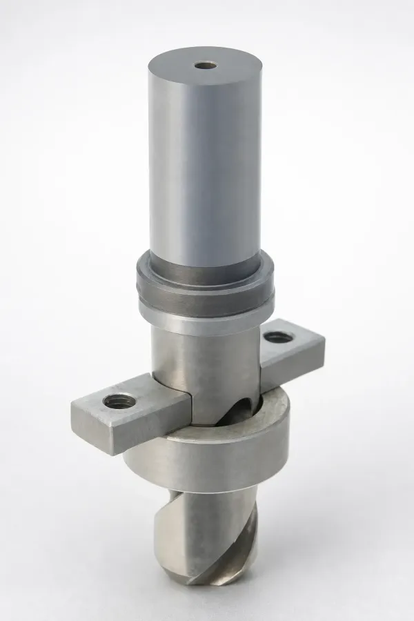
Flatness is the acceptance number, not thickness. Grind both faces and hold flatness within 0.02 mm across the full plate. Support the plate on the die shoe with a backing plate wherever the span exceeds 150 mm. Keep the spring pockets ground square to the face so the springs do not tilt the plate as they compress.
Supporting Slender Punches
Slender punches fail in bending before they fail in compression. A 1.5 mm punch in 2 mm stainless at 6 x diameter of unsupported length stands about 0.8 mm from the stripper bore at full stripping load. That deflection is enough to snap the punch at the shoulder, and it usually happens at 3,000 to 20,000 strokes rather than on the first hit.
Support means engagement, not proximity. The stripper bore should hold the punch over 1.0 to 1.5 times the punch diameter at top of stroke. The punch should also enter the bore before the tip touches the sheet. On small punches, keep the machining shoulder below the bore so the shank, not the body, carries the lateral load.
Where a punch is shorter than 4 x diameter and still delicate, add a punch guide plate or use a two-stage punch. A stepped punch with a 6 mm shank and a 1.5 mm point carries the bending load in the shank. Only the last 3 to 5 mm sits in the fine section. The same trick applies to a pilot punch that also pierces.
Retention style feeds the same design. A ball lock punch needs a retainer bore and a set screw behind the plate, while a shoulder punch loads against the backing plate. The ball lock head takes 8 to 12 mm of vertical space in the punch holder. That space decides how much stripper bore engagement is left at the top of the stroke.
Match the punch material to the job as well. Standard HSS punches above 60 HRC hold an edge well but snap under lateral load. Powder metallurgy grades and tool steel at HRC 60 to 62 give 20 to 40 percent more bending resistance. Carbide belongs only where the stripper bore clearance is under 0.01 mm and the press has excellent parallelism. Order the punches with the stripper bore size on the same drawing, cut to a matched clearance band.
Strip Control and Feeding Interaction
The stripper is part of the feed system whether the designer intends it or not. It sets the height the strip has to reach before the feed can advance. That height interacts with pilot engagement, the lifter springs and the feed roll release timing.
Sequence the cycle so the pilots are in the strip before the stripper releases it. A typical rule is 2 to 3 mm of pilot engagement in the strip at the point where the stripper plate has risen clear. If the pilots enter after the plate releases the strip, every stroke starts with the strip free to shift. The die then loses 0.05 to 0.20 mm of station accuracy.
The progressive die layout decides how much of that is possible. Station pitch, carrier width and pilot position all constrain the stripper travel. A stripper that needs 10 mm of travel on a die built for 6 mm will drag the strip on every indexing step. That is a layout problem to fix on the drawing, not a spring problem to fix on the bench.
Pressure Pads in Draw and Forming Dies
A pressure pad is a stripper with a forming job, so the force calculation changes. In a draw die the pad is a blank holder: it controls material flow into the die radius rather than simply pressing the part off the punch. Blank holder force typically runs 20 to 40 percent of the drawing force, and it goes higher for high-strength steels where springback control matters more than formability.

Too little force and the blank wrinkles in the flange: 1 to 3 mm wrinkles that show on the panel and block the die. Too much force and the material cannot flow, so the wall thins and the part tears at the punch radius. The window between those two failures is narrow on high-strength steel, often only 15 to 20 percent of the force range.
Set pressure pads with gas springs or a die cushion rather than coil springs. A cushion delivers force proportional to drawing force through the stroke. A coil spring delivers 30 to 50 percent more force at the bottom of the stroke than at the start. That force rise is what tears a thin wall in the last 5 mm of the draw.
The pad face has to be spotted to the blank, not machined flat and left. Full contact within 0.05 mm over the blank area prevents local high spots, and high spots are where the coating wears first and galling begins. On a 400 mm panel, a 0.10 mm high spot carries 30 to 50 percent of the pad load on about 5 percent of the area.
Galling and Marking Defects
Galling is material transfer from the sheet to the punch or the stripper bore. Stainless, aluminium and coated steels gall first, and the damage compounds. A picked-up lump on the punch face grows until it tears the bore, and the bore then marks every part. A 0.05 mm lump is enough to score a visible line down a visible panel.
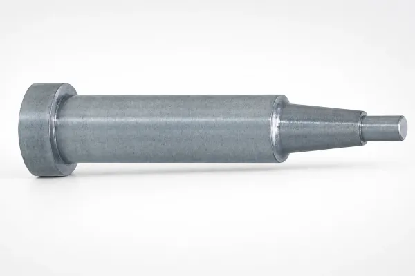
Four causes cover most cases. Clearance that is 0.005 mm too tight raises contact pressure and wipes the lubricant film. A bore polished across the direction of travel carries microscopic edges that shear metal off the shank. Dry or thin lubricant lets metal-to-metal contact start within the first 500 strokes. And a bore at 45 HRC or softer peens and holds embedded particles that then act as a lap.
Fix the contact, not the symptom. Grind and polish bores to Ra 0.2 to 0.4 µm along the direction of punch travel. Hold bore hardness at HRC 58 to 62, and open clearance by 0.005 mm when galling proves to be a pressure problem.
Coat the punch and bore as a pair with TiCN or AlCrN at 2 to 4 µm for stainless work. Where the sheet is the source, switch to a drawing lubricant with extreme pressure additives. A boundary film that survives 80 to 120 MPa of contact pressure is what keeps bare steel off bare steel. Our guide to preventing stamping die galling covers coating and lubricant selection in more depth.
Spring Life and Replacement Schedule
Springs are consumables and belong in the maintenance plan. A coil die spring designed to 20 to 25 percent of free length deflection typically holds its rated force for 500,000 to 2,000,000 strokes. Designed to the catalog maximum of 40 percent, the same spring loses 10 to 20 percent of its force within the first 250,000 strokes.
Force loss is the failure mode that hides. Shortening free length by 1 to 2 mm removes the preload, so the plate starts the stroke touching the strip and the marking and drag defects return. Check free length every 100,000 strokes against the value recorded at build, and replace a coil spring once it is 0.5 to 1.0 mm shorter.
Replace springs as a set. A stripper with three new springs and one tired spring tilts. The tilt shows up as uneven marking and a bent punch at the corner where the plate lifts first.
Write two numbers on the die maintenance card: the installed height of the spring pocket and the free length of each spring when new. Nitrogen gas springs need a charge check every 500,000 strokes and a rebuild at 1,000,000 to 2,000,000 strokes. They fail with a slow force loss rather than a break.
Inspection and Trial Acceptance for Strippers
Inspect the stripper before the die closes, not after the first crash. Verify plate flatness within 0.02 mm on a surface plate and measure every punch bore with an air gauge or a setting plug. Confirm the installed spring height against the drawing, and check that travel clears the strip by 3 to 6 mm.
Then run T1 with the numbers written down. Check for strip drag above 0.10 mm and marking depth above 0.02 mm on a visible face. Station accuracy must hold within ±0.05 mm over 30 to 50 strokes. Spring force must stay within 5 percent of design at the preload height. Record the air gauge reading for each bore and the free length of each spring in the die file at handover.
Stripper and Pressure Pad FAQ
Q1. How much stripping force does a stamping die need?
Three to ten percent of blanking force, with the share rising as the sheet gets thinner and softer. Size the spring package at 1.5 to 2.0 times that figure to cover spring force loss and rising friction as the die wears.
Q2. What clearance should a stripper plate have on the punch?
0.01 to 0.03 mm per side for punches above 3 mm and 0.005 to 0.015 mm per side below that. It must always stay tighter than the die clearance, which runs 5 to 10 percent of sheet thickness per side.
Q3. How much spring preload should a stripper use?
15 to 20 percent of working travel, so 1.2 to 1.6 mm on an 8 mm stripper. Preload keeps the plate against the strip at the top of the stroke and stops the strip from lifting with the punch.
Q4. Coil springs or nitrogen gas springs for a pressure pad?
Gas springs where force has to stay flat through a draw and pocket space is tight, since they hold within 5 percent over the stroke. Coil springs are the economical choice for stripping on most progressive dies up to about 10 kN per spring.
Q5. How thick should a stripper plate be?
25 to 30 percent of the plate span for small dies, and 30 to 40 mm on a 400 to 600 mm progressive die plate. If the plate is already built and bows, move the springs closer to the cut contour before adding thickness.
The Bottom Line
Stripper and pressure pad design comes down to five numbers. Stripping force runs 3 to 10 percent of blanking force, preload 15 to 20 percent of travel, and clearance 0.01 to 0.03 mm per side. Plate flatness stays within 0.02 mm, and the spring replacement interval belongs in the maintenance plan.
DieStrike builds stamping dies and precision tooling to IATF 16949 with ±0.005 mm tolerance, ±0.002 mm on EDM and jig grinding, HRC 62 heat treatment and 120+ machines. Standard components ship in 3 to 7 days and full die lead times run 2 to 5 weeks, with programs running for tier-1 suppliers such as TE, Amphenol, Luxshare and Dongshan. Send the strip grade, the die layout and the press data, and we will return a stripper and spring concept with the force calculation attached through the contact page.
KEEP READING
Related Reading
Stripper Plate vs Ejector Pins
When a full-face stripper beats pins, and the plate flatness and clearance numbers that separate the two.
Read articleArticleHow to Choose Die and Mold Springs
Load classes, deflection limits and stroke life for coil springs against nitrogen gas springs.
Read articleProductPunches
HSS, powder metallurgy and carbide punches ground to 0.002 mm, with matching stripper bores.
Read articleServiceStamping Die Manufacturing
IATF 16949 die building with DFM feedback in 24 hours, standard components in 3 to 7 days and 2 to 5 week lead times.
Read articleNEXT STEP
Ready to Start Your Mold?
Send us your element dimensions or part numbers — our team responds within 24 hours with pricing and lead time.

Written by
Ray ChanMold Buyer's Guide Author · Precision Mold Manufacturing Specialist. Ray helps global importers, distributors and OEMs source factory-direct molds and mold parts.