
How to Design a Hot Runner Manifold: Balance, Expansion and Seals
Table of Contents
A 24-drop manifold on a glass-filled PA66 connector tool ran 9 °C hotter at the two outer drops than it did at the center. On a 19 second cycle that sounds harmless. Across 300,000 shots it meant those two cavities produced parts 0.04 mm thicker, and the melt parked in the outer runners spent closer to 7 minutes at 265 °C instead of 4. That is long enough to char a nylon and short enough that nobody sees anything until the first black streak appears in a part.
Manifold problems rarely trace back to the machine or the setter. They trace back to decisions made on the manifold drawing: where the block is located, how far it is allowed to grow, how the runner network divides flow, how the seal lands receive their preload, and how much heater power is packed into a given length of steel. Each of those is a number, and each number has a range that works.
This guide covers the manifold body only. Nozzle selection, controller tuning, gate detail and leak repair are separate decisions with their own guides, and this article stays out of them except where a manifold dimension sets them up. It is written for mold buyers, tooling engineers and manufacturing engineers who sign the manifold drawing before steel is cut. All figures are typical published or industry values. Verify them against the steel certificate and the resin datasheet before releasing a drawing.
The Snapshot
- Expansion budget. Tool steel grows about 0.12 mm per 100 mm of length per 100 °C of temperature rise. A 600 mm H13 manifold grows 1.67 mm on the way to 250 °C, and each drop moves 0.84 mm from the center pin.
- Locate once, at the center. One hardened center pin plus guided support pads keeps growth symmetric. Hard pins on both ends of the same axis double the reaction force at the seal lands and push roughly 586 MPa of thermal stress into the block.
- Balance decides melt history. Hold melt residence time under 4 to 6 minutes for PA, PBT and POM. Runner volume above 25 cm³ per drop usually breaks that limit on a low-throughput thick part.
- Heaters run 3 to 6 W/cm². That band ramps a 40 kg manifold to setpoint and holds it there. Zone spread must settle within ±5 °C after soak before anyone judges a part quality decision on the tool.
- Torque is a hot number. M8 class 12.9 cap screws at 30 N·m cold lose 15 to 25 percent of their preload after two thermal cycles. Recheck torque at operating temperature, then again after 1,000 shots.
Why Manifold Design Fails Before the Mold Does
Four failure paths account for most manifold problems, and every one of them starts as a line on a drawing rather than an action on the shop floor.
Seal land leakage. Melt escapes where a nozzle body meets the manifold face, or where the inlet meets the sprue bushing. At 1,200 to 2,000 bar of injection pressure, a face gap of 0.02 mm is already a leak path. The escaped melt carbonizes in the air gap under the manifold, destroys the thermal break, and shifts the temperature balance of the whole plate. By the time it is found, the block usually needs a re-cut or a replacement, and a $6,000 manifold can take $20,000 of press time down with it.
Cold zones and dead corners. A runner with a sharp 90 degree turn and no radius traps melt. That trapped volume sits in the block for 12 to 20 minutes instead of 4, degrades, and then releases a slug of charred material into a cavity. One degraded slug can scrap 200 to 600 parts before an operator notices the streak on the bench. Dead ends, blind crossovers and abrupt section changes are the usual locations.
Thermal fatigue at heater and sensor grooves. Every startup puts the steel through a 200 °C excursion. A sharp internal corner at a thermocouple well is a stress riser, and a crack opens there first. On un-nitrided P20 at 30 HRC, manifold cracking typically appears between 30,000 and 80,000 thermal cycles, which on a 20 second cycle with two shifts is 6 to 18 months of running. Nitriding plus generous corner radii push that window out by a factor of two to three.
Unsupported spans and fretting. A manifold spanning 400 mm between support pads deflects under injection load, frets the spacers, and slowly loses seal contact on the outer drops. The symptom shows up as a short shot in the end cavities and gets blamed on balance, when the real cause is 0.04 mm of mid-span deflection and a set of worn spacers.
The economics are lopsided. A manifold block is 8 to 15 percent of hot runner system cost, and typical industry service data puts 40 to 60 percent of unplanned hot runner downtime behind manifold and seal failures. Press time alone runs $75 to $150 per hour, before the crew cost of $60 to $120 per hour. A $6,000 manifold that fails at 40,000 shots costs more than a $12,000 manifold that runs 500,000.
Five checks on the drawing remove most of that risk: an expansion budget, a single center location, a balance method with a residence time limit, seal and groove dimensions, and a heater power density with a zone tolerance. The rest of this article works through them in that order.
Manifold Anatomy: Five Zones That Decide Performance
A manifold is a heated distribution block, but it is not one system. Five functional zones carry the design load, and each needs numbers on the drawing rather than a note in a review meeting.
1. Inlet and sprue seat. The inlet bore carries full injection pressure through a 12 to 20 mm passage. The seat face needs 60 to 75 percent contact area against the sprue bushing or machine nozzle, with flatness held to 0.01 mm and a finish of Ra 0.4 µm. The pass condition is a lapped seat that shows even contact after blueing, not a face that was milled flat and assumed good.

2. Runner network. Full-round runners of 6 to 12 mm diameter suit unfilled engineering resins, and 8 to 14 mm suits glass-filled grades. Every turn carries an inside radius of at least 1.5 times the runner diameter, and dead ends are milled flat and polished to Ra 0.4 µm so degraded melt has no corner to collect in. Flow length from the inlet to each drop is a controlled dimension on the drawing, not a consequence of layout.
3. Nozzle drop bores. Drop bores are machined to H7 and sized for 0.03 to 0.06 mm diametral clearance on the nozzle body at 20 °C. That clearance closes as the block heats, because bore and body expand at slightly different rates: at 240 °C the running clearance is nearer 0.01 mm. Less than that and the nozzle locks in the bore, which means a re-cut and a new nozzle body.
4. Heater and sensor map. One control zone per 150 to 250 mm of manifold length keeps gradients under 10 °C across the block. A 900 mm manifold for a large appliance housing tool typically needs 5 to 7 zones, each with a thermocouple well at least 25 mm from a heater groove and 15 mm from the runner wall. That map belongs on the drawing, not only in the controller memory.
5. Support and location plane. The manifold never sits directly on the plate. Titanium or 420 stainless spacers hold a 3 to 5 mm air gap on the top face and insulate the bottom face. That gap is the thermal break and, on the unguided axis, the expansion allowance at the same time.
Every zone above carries a tolerance in the drawing package. Systems that ship with undefined numbers are the systems that leak in the first month. DieStrike machines manifolds and hot halves as part of its hot runner systems work, with runner networks, seal seats and locating features cut to ±0.005 mm and hardened components held to ±0.002 mm.
Natural Balance vs Artificial Balance: Melt Residence and Shear
Balance decides whether every cavity fills at the same moment with the same melt history. Two methods get there, and both need numbers on the drawing.
Natural balance gives equal flow length from a single inlet to every drop. An 8-cavity square layout with a symmetric runner cross achieves it with identical branch diameters. The pass condition is a flow length spread under 5 mm between the longest and the shortest path, measured on the machined runner rather than on the layout sketch. Any branch that needs a jog to clear a nozzle bore breaks natural balance unless the jog is mirrored on all branches.
Artificial balance compensates unequal flow lengths by changing diameter instead. A branch that is 40 mm longer than its twin gets a diameter 0.5 to 1.0 mm larger so the pressure drop matches. This is the normal answer for family molds and for two-cavity tools with unequal part weights. It costs machining time because every branch is a separate cut, and it only holds for one resin at one melt temperature. A viscosity change of 20 percent moves an artificially balanced system off balance by 3 to 8 percent on part weight.
Residence time sets the limit on runner volume. A full-round 10 mm runner holds 0.785 cm³ per centimeter of length, so a 700 mm manifold with 10 mm runners carries about 55 cm³ of melt. Residence time is that volume divided by melt throughput. At 0.5 cm³/s the melt turns over every 110 seconds, which is healthy. On a thick part running 0.15 cm³/s, the same block holds melt for about 6 minutes, and PBT or POM starts to degrade at that point.
Typical upper limits on residence time are 2 to 3 minutes for PVC, 3 to 5 minutes for POM, 4 to 6 minutes for PA, PBT and ABS, and 8 to 10 minutes for PPS and PEEK. Treat those as published starting points and confirm them with the resin supplier for the specific grade, colorant package and flame retardant system in use.
Shear rate is the second limit. Runner shear rate follows γ = 4Q / (πR³), with Q in cubic millimeters per second and R in millimeters. A flow of 40 cm³/s through a 10 mm runner gives 4 × 40,000 ÷ (3.1416 × 125) = 407 s⁻¹. Most engineering resins fill well between 100 and 2,000 s⁻¹ in the runner. Under 100 s⁻¹ the melt advances too slowly and freezes in a cold spot, and glass-filled grades above 3,000 s⁻¹ risk fiber damage and surface splay.
Balance also shows up in part weight. Cavity to cavity weight spread should stay within 2 to 3 percent of the mean on the first trial, and a spread above 5 percent means the runner network is doing the metering rather than the process. For the decision between a heated manifold and a cold runner in the first place, the trade-offs are covered in this hot runner vs cold runner comparison. For automotive tools with 16 cavities and up, the drop count and balance method that hold up in production are covered in this hot runner selection guide for multi-cavity automotive molds.
Thermal Expansion Calculation: 0.12 mm per 100 mm per 100 °C
Thermal growth is predictable, and the formula is short: ΔL = L × α × ΔT, where L is the length at 20 °C, α is the coefficient of thermal expansion for the steel, and ΔT is the working temperature rise from ambient.
For hot-work tool steels α sits between 10.4 and 12.6 × 10⁻⁶ per °C. That works out to about 0.12 mm of growth per 100 mm of manifold length for every 100 °C of rise, which is the number to keep in your head during drawing review. A 600 mm H13 manifold running at 250 °C grows 1.67 mm from the cold state, a 900 mm manifold grows 2.51 mm, and a 1,200 mm block for a large appliance tool grows 3.35 mm.
The same growth lands on the diagonals, which is where it usually gets forgotten. On a 600 × 400 mm plate the diagonal is 721 mm, and that diagonal grows 2.01 mm at 250 °C, so a drop positioned on the diagonal moves 1.00 mm from the center pin instead of 0.84 mm. Every drop bore, every seal land and every locating slot carries a dimension that comes from this arithmetic.
| Manifold steel | α (10⁻⁶/°C) | Growth on 400 mm | Growth on 600 mm | Typical manifold use |
|---|---|---|---|---|
| P20 / 1.2311 (30 HRC) | 12.6 | 1.13 mm | 1.70 mm | Runs to 220 °C, low cavitation, budget tools |
| 1.2343 / H11 (46 HRC) | 12.2 | 1.10 mm | 1.65 mm | General purpose, nitrided, good fatigue life |
| H13 / 1.2344 (48 HRC) | 12.4 | 1.12 mm | 1.67 mm | High cavitation and glass-filled resins |
| 1.2083 / 420 stainless | 10.4 | 0.94 mm | 1.40 mm | Corrosive resins such as PVC and POM with acid residue |
← swipe to scroll →
Table note: growth is calculated with ΔL = L × α × ΔT from 25 °C to 250 °C, so ΔT = 225 °C. Coefficients are typical published values for each grade and shift slightly with heat treatment and direction of rolling, so confirm against the steel certificate before you commit a clearance dimension to the drawing.
Two design rules follow from the table. First, size the air gap and the seal preload for the growth of the specific steel, not for a rule of thumb carried over from a P20 tool. Second, allow growth on the axis that has no locating feature. A block that cannot grow on any axis grows into the cavity face instead, and 1.67 mm of movement across a nozzle face is a leak with a clock on it.
Center Locating Pin and Guided Growth
Growth has to go somewhere, and the drawing has to say where. The standard answer is one hardened locating pin at the center of the runner cross, plus support pads that allow sliding in the radial direction.
One pin defines the zero point. A 12 mm hardened dowel in an H7/h6 fit with 30 to 40 mm of engagement does the job. Every dimension on the manifold, including every drop bore, is located from that center. Growth then radiates outward from the pin in all directions, each drop moves the same distance, and the seal preload stays even across the block.
Know how far each seal land travels. A 600 mm manifold that grows 1.67 mm moves 0.84 mm from the center pin to the outer drop. The seal land and the nozzle body must absorb that movement while the manifold face stays in contact with the plate. Clearance in the drop bore plus a compliant tip design handles it. On the plate side, locating slots need at least 1.0 mm of travel beyond the calculated growth, which puts the slot clearance at 2.0 to 2.5 mm on a 600 mm block.

Blocking growth creates real stress. If pins at both ends of the same axis prevent all movement, the manifold behaves like a fully constrained bar and thermal stress follows σ = E × α × ΔT. With E = 210 GPa, α = 12.4 × 10⁻⁶ per °C and ΔT = 225 °C, that stress reaches 586 MPa. That is roughly 40 percent of the yield strength of 48 HRC H13 and far above what M8 cap screws can hold at 30 N·m. Constrained steel does not compress quietly: it bends the plate, frets the pads and opens the seal lands.
Guided axis versus free axis. A common pattern is a round center pin for the full zero point, plus one diamond or slotted pad that controls rotation without controlling radial movement. Valve gate manifolds need angular location for pin alignment, so the second locating feature must be a slot cut perpendicular to the growth direction. A slot clearance of 0.10 mm on a 20 mm width holds the manifold within 0.02 mm angularly while still letting it grow.
Bolt holes are not locators. Manifold bolt holes are drilled 0.5 to 1.0 mm oversize with hardened washers under the heads. A bolt that clamps the block against expansion turns the block into a spring and the bolts into a fatigue test. Torque, not fit, holds the manifold down.
Support pads carry the injection load. A 10 mm runner bore at 1,500 bar generates about 11,800 N, or 1.2 tonnes, on the manifold cross section. Four pads of 300 mm² each take that load at roughly 9.8 MPa of bearing stress, which is comfortable for a hardened spacer. The working rule is one pad under every drop position plus one at each free end, so the block never spans unsupported more than 300 mm.
Plate Thickness and Runner Section Ratio
Manifold thickness is driven by runner diameter, heater grooves, seal seats and bending stiffness. Working those four items in order is faster than guessing at a plate size and then adding steel to fix a deflection problem.
Web under the runner runs 0.8 to 1.0 times the runner diameter. An 8 mm full-round runner needs at least 6.5 to 8 mm of steel between the runner bottom and the seal face or the plate bottom. Less web than that means the seal land deflects under injection pressure, and a land that moves 0.02 mm leaks. Total plate thickness typically lands at 2.0 to 3.0 times the runner diameter for a clean section, which puts an 8 mm runner manifold at 35 to 45 mm thick and a 12 mm runner manifold at 55 to 80 mm.
Heater groove depth and position. Grooves run 5 to 8 mm deep on both faces of the plate, with 8 to 10 mm of steel left between the groove bottom and the runner wall. Closer than that produces a hot stripe over the runner, which shows up as splay or a silver streak in the cavity nearest that heater. Thermocouple wells sit 15 to 25 mm from the runner wall and at least 20 mm from the nearest heater groove.
Thickness carries stiffness. Between support pads the manifold spans 200 to 300 mm at 200 °C with about 1.2 tonnes on the runner cross. A 40 mm block deflects roughly 0.01 mm over a 250 mm span under that load, which holds seal contact. A 25 mm block deflects nearly 0.04 mm, which pushes the outer seal land out of contact and produces the short shot that gets misdiagnosed as poor balance.
| Runner diameter | Minimum web | Plate thickness | Max unsupported span | Typical drop count |
|---|---|---|---|---|
| 6 mm | 5-6 mm | 25-35 mm | 250 mm | 4-8 drops, small parts, PP and ABS |
| 8 mm | 6.5-8 mm | 35-45 mm | 300 mm | 8-16 drops, general engineering resins |
| 10 mm | 8-10 mm | 45-60 mm | 300 mm | 16-32 drops, PA and PBT connector work |
| 12 mm | 9.5-12 mm | 55-80 mm | 350 mm | 16-32 drops, glass-filled grades |
| 14 mm | 11-14 mm | 70-100 mm | 350 mm | Large parts, high throughput, up to 48 drops |
← swipe to scroll →
Table note: thickness figures assume a full-round runner in H13 with 5 to 8 mm heater grooves on both faces and a pad grid at 250 to 300 mm. A manifold with a long thin section under an inlet bore should be checked for deflection on that section alone, because the local span, not the average plate thickness, decides whether the seal land stays in contact.
Weight follows thickness, and weight needs support. A 700 × 400 × 40 mm H13 manifold weighs about 88 kg, and a 700 × 400 × 55 mm block weighs 120 kg. Injection pressure pushes against that mass on every shot, so a pad grid at 250 to 300 mm spacing is not optional. Thickness is also one of the cheapest decisions in the tool: adding 10 mm to a 700 × 400 mm plate adds 22 kg of stock, worth roughly $150 to $250, and removes 0.03 mm of mid-span deflection.
Split the block when growth gets large. Above roughly 800 mm of length a single manifold grows past 2.2 mm and starts fighting its own drops. Two blocks with a bridged inlet, each under 500 mm, cut the growth per block to about 1.4 mm and simplify both the drawing review and the heater map. The bridge carries its own seal and its own expansion allowance.
Edge Gate Sealing and O-Ring Groove Dimensions
Melt at 1,500 bar finds every gap in the system. Two sealing methods handle it, and both live in the manifold drawing.
Metal-to-metal seal lands. The nozzle body or the inlet presses a narrow land against the manifold face. That land needs 1.5 to 2.5 mm of face width, flatness within 0.005 mm and a surface finish of Ra 0.4 µm. Contact stress of 100 to 200 MPa is the target, and it comes from thermal growth plus bolt preload rather than from hand tightening. A land that only touches after the manifold reaches 200 °C will leak during warm-up, which is why preload is set cold and verified hot.
O-ring seals on lower temperature interfaces. Material selection comes first. FKM holds 200 to 205 °C continuously and about 230 °C short term, silicone tops out near 200 °C, and FFKM is the practical choice above 240 °C. A 250 °C manifold running FKM seals hardens in 3,000 to 6,000 hours and starts weeping at the gland. Similarly, a nitrile ring rated at 90 °C has no place anywhere on a heated half.

Groove dimensions matter more than the ring. Cut a groove for a 2.0 mm cord 2.6 to 2.8 mm wide and 1.45 to 1.55 mm deep. That leaves 20 to 25 percent squeeze when the parts close, which is the band that seals without permanently deforming the cord. For a 3.0 mm cord, use 3.8 to 4.0 mm width and 2.20 to 2.30 mm depth. Groove floors and walls run at Ra 1.6 µm or better, inside corners break with a 0.2 mm radius, and the entry edge gets a 0.2 mm chamfer so the ring is not nicked on assembly.
| Cord diameter | Groove width | Groove depth | Squeeze | Typical use on a manifold |
|---|---|---|---|---|
| 1.5 mm | 1.9-2.1 mm | 1.05-1.15 mm | 20-25% | Small drop glands on low pressure tools |
| 2.0 mm | 2.6-2.8 mm | 1.45-1.55 mm | 20-25% | Standard drop and inlet glands |
| 2.5 mm | 3.1-3.4 mm | 1.80-1.90 mm | 20-25% | Manifold to plate static seals |
| 3.0 mm | 3.8-4.0 mm | 2.20-2.30 mm | 20-25% | Inlet seals on large blocks |
| 4.0 mm | 5.0-5.3 mm | 2.95-3.05 mm | 20-25% | High pressure inlet, 250 °C and above |
← swipe to scroll →
Table note: dimensions follow typical elastomer gland practice for static seals with a 20 to 25 percent squeeze. At a 250 °C manifold surface, the ring sees the local steel temperature, not the setpoint of the zone, so measure the gland temperature before choosing the compound.
Put the groove in the part you can replace. A groove cut in the manifold face can be re-cut twice before the block is scrap, and each re-cut costs a press day. A groove in a nozzle body is a $200 part. Most drawings put the gland in the smaller, softer part and leave the manifold face as a lapped seal land.
A thermal gate is a seal too. On an edge gate, melt freezes across the gate for 0.5 to 1.0 mm and that frozen plug holds injection pressure for the rest of the cycle. A gate diameter of 0.8 to 1.5 mm with a 0.5 to 1.0 mm land produces a gate that breaks clean without stringing. A gate that is too large never freezes fully, drools on every cycle, and looks like a seal failure when it is a gate sizing problem.
Heater Power Density and ±5 °C Zone Control
Manifold heaters fail in two ways: too little power to hold setpoint, or too much power concentrated in a short length. Both show up in the first trial, and both are visible on the drawing before the block is machined. A DFM review of the heater layout, bore diameter and heated length catches both failure modes at the drawing stage, where the fix is a pencil edit rather than a re-cut block.
Power density is a ratio, not a wattage. Calculate it as W ÷ (π × D × L), with D and L in centimeters. A 400 W cartridge in a 12 mm bore over a 200 mm heated length gives 400 ÷ (3.1416 × 1.2 × 20) = 5.3 W/cm². Manifold heaters in an air-gap design run best between 3 and 6 W/cm². Nozzle bodies with metal-to-metal contact can carry 6 to 10 W/cm², because the heat has a direct path out of the sheath. Above about 12 W/cm² the sheath runs 80 to 150 °C hotter than the block, and cartridge life drops to 2,000 to 5,000 hours from the 20,000 hours a correctly loaded heater can reach.
Sizing for warm-up. H13 needs about 460 J per kilogram per °C. A 40 kg manifold raised 225 °C absorbs about 4.1 MJ, and the plate, spacers and insulation take another 20 to 35 percent on the way. Installed power of 12 to 20 kW per manifold covers that load plus the standing losses into the plate and the air gap, and lets the controller ramp at 30 to 50 °C per minute. Faster ramps of 100 °C per minute put the seal lands ahead of the manifold body and open a gap during startup, which is exactly when a leak starts.
Soak before you judge. A manifold needs 20 to 30 minutes at setpoint before the thermal map is stable, because the plate and the spacers come up more slowly than the block. A zone tolerance of ±5 °C across the block is the normal production target, and optical or medical tools tighten that to ±2 to 3 °C. A single zone that drifts 10 °C from setpoint after soak points to a thermocouple or a heater, not to controller tuning. A hot runner tool at 250 °C with a 6 kW controller on each half of the plate behaves differently from the same tool on a single 12 kW unit, because the zones interact through the steel.
Thermocouple placement decides the reading. Wells sit 15 to 25 mm from the runner wall and at least 20 mm from the nearest heater groove, with the sensor spring loaded against the well bottom. A thermocouple resting 3 mm off the bottom reads 15 to 40 °C low and the zone runs hot to compensate. Type J couples cover 750 °C and stay accurate across the 200 to 300 °C window manifolds use, which is why most hot runner controllers ship with that type.
Every contact shortcut costs watts. A steel support pad bridging the manifold to the plate conducts 20 to 40 W out of the block and cools the runner above it. Titanium spacers conduct about a third of that, and the 3 to 5 mm air gap does the rest of the work. Heaters on the outer 100 mm of a large block need 10 to 20 percent more power density than the center, because the ends lose heat on three faces instead of one. That is also why the end zones on a 900 mm manifold are the ones that run cold when the installed power is sized on average rather than at the ends.
Leak-Free Assembly: Preload, Torque and Thermal Cycles
A manifold seal is a clamped joint that cycles from 25 °C to 250 °C hundreds of times a year. Preload, not torque, is what keeps melt inside, and torque is only the way preload gets set.
Target 60 to 75 percent of bolt yield. A class 12.9 M8 cap screw has about 36 kN of proof load, so the working clamp load is 22 to 27 kN. Torque is a rough proxy for that with dry threads: M6 takes 14 to 16 N·m, M8 takes 30 to 35 N·m, M10 takes 55 to 65 N·m and M12 takes 90 to 105 N·m. Lubricated threads reach the same preload at 20 to 25 percent less torque, which is why the assembly sheet must state whether threads are dry, oiled or coated. Two fitters using different lubricants on the same manifold produce two different clamp loads, and one of them leaks.
Thermal cycling costs preload. The manifold, the bolts and the plate expand at different rates, and the washer stack relaxes. Measured cold, a bolted manifold joint typically loses 15 to 25 percent of its preload after two full thermal cycles. That is normal behavior, and the answer is procedure rather than a larger bolt: torque cold, run two heat cycles to setpoint with a 30 minute soak each, re-torque at operating temperature, then re-torque once more after 1,000 shots. After that second check the joint is stable and an annual torque check is enough.
Use a sequence, not one pass. Tighten in three passes at 30, 60 and 100 percent of final torque, working outward from the center of the block in a cross pattern. A single pass to full torque on a 600 mm manifold tips the block, opens the far seal land, and leaves a leak path open until thermal growth happens to close it. A torque log with the wrench setting, the date and the technician initials takes five minutes and settles most supplier arguments later.
Verify with a leak test, not with a look. After assembly, pressure test the water circuit at 1.5 times working pressure for 10 minutes, and test the melt path with nitrogen at 30 bar while brushing soap solution on every seal land and groove. A leak that appears only at 250 °C is a preload or flatness problem rather than a seal material problem, and the blueing check on the land tells the two apart in minutes. When a leak does develop in service, the sequence for finding it without pulling the whole stack apart is set out in this hot runner leak troubleshooting guide.
Manifold Steel Grades and Coatings: P20, 1.2343 and H13
Steel choice on a manifold is decided by three demands: hot strength at 250 °C, resistance to thermal fatigue at heater grooves, and cost. Hardness alone does not settle it.
P20 and 1.2311 at 30 to 34 HRC suits low cavitation tools running to 220 °C where the budget is tight. It machines quickly and holds seal flatness well. It does not suit glass-filled resins, and an un-nitrided P20 block will crack at thermocouple grooves somewhere between 30,000 and 80,000 thermal cycles. If P20 is chosen, budget for nitriding before the first run.
1.2343 and H11 at 46 to 48 HRC is the general purpose manifold steel. Nitride it to 1,000 to 1,100 HV with a case of 0.05 to 0.15 mm, keep the seal lands masked and lapped, and it will run millions of cycles without cracking at a well radiused heater groove. It resists the softening that a P20 block shows after a few hundred hours at 250 °C.
H13 and 1.2344 at 48 to 52 HRC is the choice for high cavitation and glass-filled grades, where the inlet bore and drop seats see abrasive melt at high pressure. Its hot hardness holds up at 250 to 280 °C, and its thermal fatigue resistance is the reason high-drop-count manifolds are usually specified in this grade. A 48 HRC block also takes a lapped seal land that survives repeated re-cuts.
1.2083 and 420 stainless at 48 to 54 HRC is specified for PVC and for resins with acidic residue, where a carbon steel manifold corrodes at the water and seal interfaces. Its expansion coefficient of 10.4 × 10⁻⁶ per °C is the lowest in the table above, which is a genuine advantage on a long block, but it costs two to three times a P20 block and machines more slowly.
Coatings serve specific problems and each has a boundary. Nitriding adds fatigue and wear resistance on the whole block at low cost. PVD coatings such as TiAlN, 2 to 4 µm thick at roughly 3,000 HV, resist abrasive wear on gate seats and drop bores. Electroless nickel at 25 to 50 µm and 500 to 600 HV protects water channels and corrosive interfaces. DLC at 2 to 5 µm reduces friction where sliding surfaces fretted. None of them belongs on a seal land: three micrometers of coating edge buildup changes local flatness, and a land that was lapped to 0.005 mm no longer seals. Mask every seal face and gate seat before coating, and re-lap after coating if the drawing calls for a coated surface that also seals.
Heat treatment and verification close the loop. Stress relieve a manifold billet at 550 to 600 °C before final machining, not after, because stress relief moves the block. Verify incoming steel by hardness and chemistry against its certificate, then check flatness of the seal faces on the finished block. A three point hardness spread of 3 HRC across a manifold changes fatigue life far more than it changes thermal growth, which moves less than 0.1 percent, so it is a durability check rather than a dimension check.
Assembly and Trial Inspection Checklist
A manifold is signed off on measurements taken before the first shot and after four hours of running, not on how the block looks on a bench. The checklist below is what to write into an assembly and trial record.
Cold fit check. Verify the 3 to 5 mm air gap at eight points with a feeler gauge, the drop bore clearance at 0.03 to 0.06 mm, and the center dowel fit. Check that every locating slot has at least 1.0 mm of travel beyond the calculated growth on a 600 mm block.
- Electrical checks. Heater resistance within 5 percent of the nameplate value, insulation resistance above 100 MΩ at 500 V, thermocouple continuity and correct polarity, and a zone wiring map that matches the drawing. A zone wired to the wrong thermocouple holds the wrong temperature and no controller alarm catches it.
- Blueing check. Seal lands show even contact, with at least 60 percent contact area on the inlet seat and a continuous ring on every drop seat.
- Torque log. Three passes at 30, 60 and 100 percent, cold and then at operating temperature, with values recorded per bolt.
- Thermal map. Eight to twelve contact temperature points, a 30 minute soak, and a spread within ±5 °C across the forming zone. A single zone off by 10 °C is a fault to fix before any part is judged.
- First shot assessment. Weight per drop within 2 to 3 percent of the mean, no short shot on the outer drops, gate break clean on every drop, and no sign of splay over the runner line.
- Four hour run. Cycle time held within 3 percent, scrap rate flat, and heater power draw stable on every zone. A zone whose power creeps up during the run has a heater or a short circuit developing.
- Leak inspection. Air gap clean under the manifold, no weep at the seal lands, no melt film in the plate pockets, and a repeat pressure test on the water circuit after the run.
- Documentation. CMM report on seal faces and drop bores, steel certificates, zone map, torque log, wiring diagram and the thermal map, all filed against the tool number.
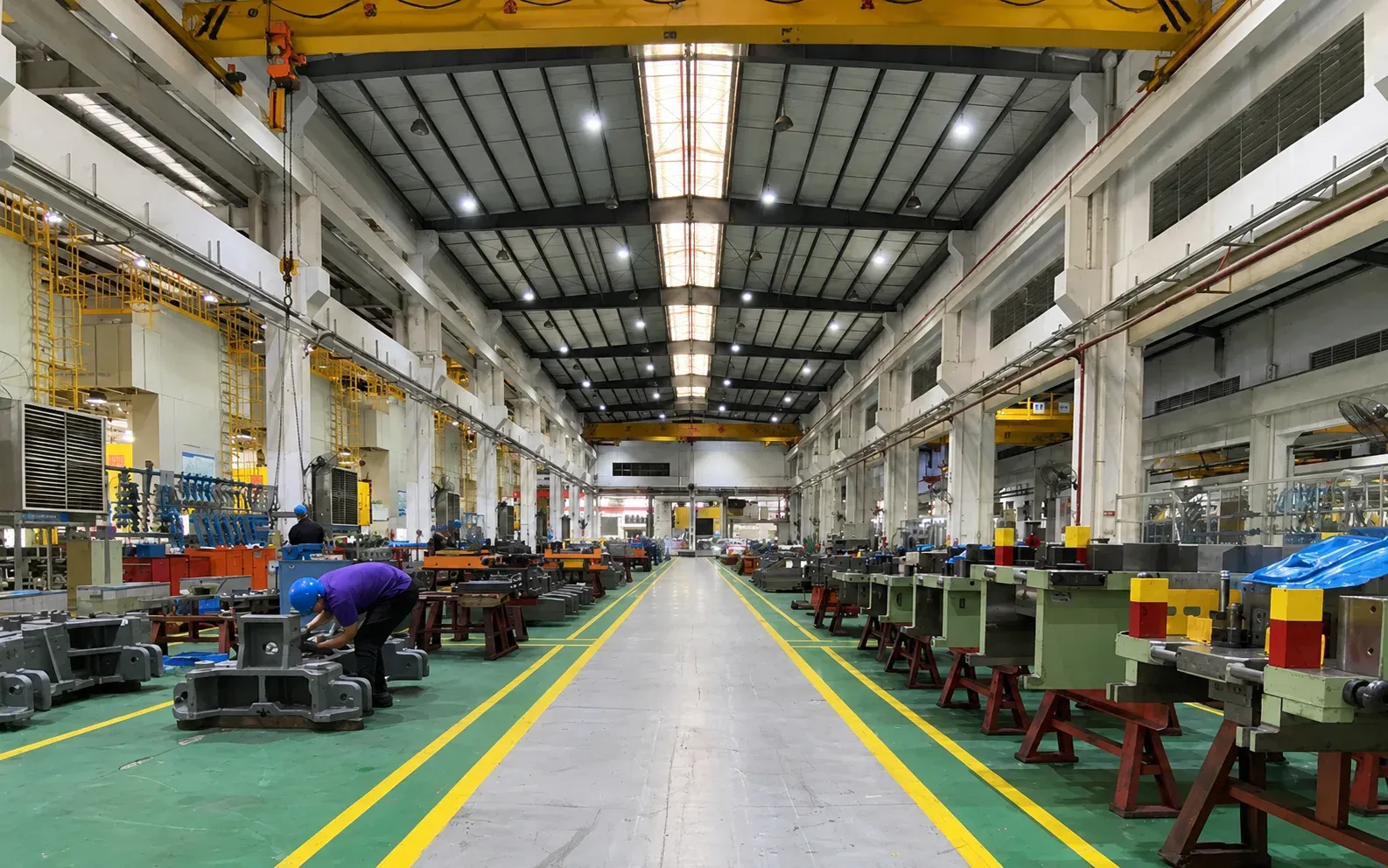
DieStrike builds manifolds and hot halves to these checks, with mold accuracy held to ±0.005 mm, part-forming geometry to ±0.002 mm, cavity heat treatment at HRC 62 where the geometry demands it, and injection mold lead time of 2 to 5 weeks from design freeze. Standard manifold components such as sprue bushings, locating pins and heater hardware ship in 3 to 7 days, which keeps a manifold repair from waiting on a custom cut. The wider acceptance sequence for a new system, including the process window study and the drop by drop study, is set out in this hot runner system validation guide.
Hot Runner Manifold Design FAQ
Q1. How do I calculate how much a manifold will grow?
Use ΔL = L × α × ΔT. For hot-work tool steel, α is about 12 × 10⁻⁶ per °C, so the working shortcut is 0.12 mm per 100 mm of length per 100 °C of rise. A 600 mm H13 manifold from 25 °C to 250 °C grows 1.67 mm, which is 0.84 mm from a center pin to each outer drop. Size slot clearance, air gaps and drop bore clearance from that number for the specific steel rather than from a rule of thumb.
Q2. Where should the manifold be located in the plate?
At one point, in the center of the runner cross, with a hardened dowel in an H7/h6 fit and 30 to 40 mm of engagement. Support pads then allow radial sliding. If you pin both ends of the same axis, the block is fully constrained, thermal stress reaches roughly 586 MPa and the seal lands open. Bolt holes should be 0.5 to 1.0 mm oversize so they never act as locators.
Q3. Natural or artificial balance for an 8-cavity tool?
Natural balance if the layout allows equal flow length to every drop, with a measured flow length spread under 5 mm. Artificial balance is the answer for family molds and for cavities with unequal part weights, and it works by adding 0.5 to 1.0 mm of diameter to a branch that is about 40 mm longer. Both methods should land cavity to cavity weight spread within 2 to 3 percent on the first trial.
Q4. What O-ring groove should I cut for a 2 mm cord at 250 °C?
Groove 2.6 to 2.8 mm wide and 1.45 to 1.55 mm deep, giving 20 to 25 percent squeeze, with Ra 1.6 µm or better walls, a 0.2 mm inside radius and a 0.2 mm entry chamfer. Choose the compound for the gland temperature, not the setpoint: FKM is good to about 200 °C continuous, and a 250 °C gland needs FFKM.
Q5. What heater power density should I specify on a manifold?
Three to 6 W/cm² for cartridge heaters in an air-gap manifold, calculated as W ÷ (π × D × L) with D and L in centimeters. Nozzle bodies with metal contact can carry 6 to 10 W/cm². Above 12 W/cm² the sheath runs 80 to 150 °C hotter than the block and cartridge life falls to 2,000 to 5,000 hours. Size installed power so a 40 kg manifold, which absorbs about 4.1 MJ, reaches setpoint on a 30 to 50 °C per minute ramp.
Q6. Why do manifold bolts come loose after a few weeks?
Because thermal cycling removes preload. A bolted joint typically loses 15 to 25 percent of its cold preload after two heat cycles as the manifold, bolts and washers expand at different rates. Torque cold, re-torque at operating temperature, and check again after 1,000 shots. If bolts still loosen, check whether the holes are acting as locators: oversize holes and hardened washers are what let the block grow instead of fighting its fasteners.
The Bottom Line
Manifold design is a short list of numbers that have to be right before steel is cut: a 0.12 mm per 100 mm per 100 °C growth budget, one hardened center location with guided support pads, a balance method with residence time under 4 to 6 minutes, a runner and plate ratio that holds seal contact, O-ring grooves at 20 to 25 percent squeeze, and 3 to 6 W/cm² of heater density holding ±5 °C after soak. Get those six items onto the drawing and most manifold leaks never happen.
DieStrike builds injection molds and hot halves under an IATF 16949 quality system with 120+ machines, mold accuracy of ±0.005 mm, part-forming geometry of ±0.002 mm and HRC 62 cavity heat treatment. Manifold and hot half lead time runs 2 to 5 weeks from design freeze, standard components ship in 3 to 7 days, and the same heavy-cavitation programs run for connector and electronics OEMs including TE Connectivity, Amphenol, Luxshare and Dongshan Precision. Contact us with the manifold layout and the resin, and the expansion and runner check comes back with the DFM report.
KEEP READING
Related Reading
How to Select Hot Runner Nozzles: Open Gate vs Valve Gate
Nozzle type, tip geometry and gate vestige rules for the drop that sits in your manifold.
Read articleArticleHot Runner vs Cold Runner: Which Is Right for Your Mold?
Cost, scrap and cycle comparison that decides whether the manifold is worth building at all.
Read articleArticleHow to Design Cold Runners: Sizing, Layout and Scrap Rules
Runner sizing and layout rules for the cold runner route, with scrap and regrind limits.
Read articleServiceInjection Mold Manufacturing
IATF 16949 mold and hot half building with manifold design review and DFM feedback in 24 hours.
Read articleNEXT STEP
Ready to Start Your Mold?
Send us your element dimensions or part numbers — our team responds within 24 hours with pricing and lead time.

Written by
Ray ChanMold Buyer's Guide Author · Precision Mold Manufacturing Specialist. Ray helps global importers, distributors and OEMs source factory-direct molds and mold parts.