
How to Choose a Hot Runner for Multi-Cavity Automotive Molds
Table of Contents
Here is a failure mode we see repeated in tooling audits. A Tier 1 supplier approved a 64-cavity hot runner for an automotive connector housing. Cavity 1 filled in 2.1 seconds. Cavity 64 took 3.4 seconds.
The X-manifold had unequal flow lengths. The mold scrapped 4,300 parts before the imbalance was found. Rework cost $38,000 and the launch slipped 6 weeks. The hot runner itself was not broken. The selection was wrong.
Hot runner selection for automotive connector molds is an eight-link chain. The links are cavity count, layout, manifold type, gate type, nozzle tip, resin compatibility, thermal control and controller. Break any link and the mold delivers imbalance, scrap, or a gate vestige that fails a connector appearance spec. This guide walks the chain in order, with numbers you can put in an RFQ. Figures are typical industry values unless stated otherwise.
The Snapshot
- 64-cavity hot runner systems run $65,000 to $120,000, typically 15% to 25% of total mold cost.
- An H-manifold stays naturally balanced at 2, 4, 8, 16, 32 and 64 drops. An X-manifold balances 4-way patterns only.
- PA66 GF30 and LCP demand 44+ HRC wetted steel, and LCP leaks through 0.02 mm gaps at 330 °C.
- Thermal target: ±2 °C at every nozzle tip, with 4 to 8 controller zones per 8 cavities.
- DieStrike returns DFM feedback in 24 hours and a hot runner selection with cost breakdown in 48 hours.
Start With Cavity Count and Layout
Cavity count is a volume decision, not a habit. At 6,000 productive hours per year, 80% utilization and a 30 s cycle, one cavity delivers about 576,000 parts. A 2,000,000 part program needs 4 cavities. A 10,000,000 part platform needs 16 to 24. A 40,000,000 part global connector program needs 64.
Housing shot weights run 2 to 15 g, so cavity pitch lands between 25 and 60 mm. Two-row and four-row layouts dominate because they keep gate-to-gate flow length equal for every drop. Equal flow length is natural balance. Unequal flow length forces nozzle-diameter tuning, and a 64-cavity mold rarely tunes well.
Balance rule. Measure flow length from the manifold inlet to each gate. The longest path and the shortest path must stay within 5% of each other. Beyond that, expect fill-time scatter of 0.3 s or more across the mold.
Layout rules for 8 to 64 drops
Single-row layouts handle 8 to 16 cavities at 25 to 40 mm pitch. Two-row layouts handle 16 to 64 cavities at 30 to 60 mm pitch. Four-row layouts suit 32 to 64 cavities but widen the manifold and double plate machining. Do not let one drop feed two cavities unless the part is symmetrical and the toolmaker has proven the fill pattern.

A 16-cavity two-row layout at 30 mm pitch fits a 350 × 350 mm cavity plate area, typical for connector housing tools. A 64-cavity four-row layout needs roughly 600 × 500 mm. Keep the cavity plate size inside your mold base standard, or the hot half grows beyond the platen.
Manifold Type: H, X or Stack
H-manifold. The H layout splits flow evenly at every branch. Every path from sprue to gate stays the same length, so the system stays naturally balanced at 2, 4, 8, 16, 32 and 64 drops. That makes H the default for 8 to 64 cavity connector molds. An 8-drop H manifold runs about $9,000 to $18,000. A 64-drop unit runs $65,000 to $120,000, typical figures.
X-manifold. The X layout feeds four gates from one central point and balances exactly four drops. For 8, 16 or 64 cavities you must stack X units or hybridize with H branches, and every junction becomes a potential dead spot. Use X only when the footprint is tight and the mold has 4 or 8 drops.
Stack manifold. A stack mold opens on two parting lines, and the hot runner feeds both levels. Output doubles per clamp tonnage: a 32 + 32 stack needs the clamp force of a 32-cavity mold, not a 64. Stack tooling costs 30% to 50% more than a flat 64-cavity mold and complicates setup. Choose stack only for very high volume on a locked long run.
Gate Type and Nozzle Tip Selection
Gate type and nozzle tip are one decision, made together. Connector housings run two families of gates, covering gate diameters from 0.5 to 6 mm: pin-point and valve gate.
Pin-point. A pin-point gate leaves a vestige of 0.3 to 0.8 mm. Gate diameter runs 0.5 to 1.2 mm on 2 to 15 g parts. It suits PA66 GF30 and PBT, where shear heating helps fill thin walls. The tip is the wear part: glass fibers erode standard H13, so spec tips hardened to 48 to 52 HRC or tungsten carbide-tipped nozzles. Typical tip life on GF30 is 300,000 to 500,000 shots.
Valve gate. A valve gate seals with a hardened pin of 2 to 6 mm and leaves near-zero vestige. It adds $300 to $800 per drop plus a cylinder and air line per drop, typical figures. Spec valve gates for LCP, for class-A cosmetic surfaces, and for housing gates above 1.5 mm.
Pin-point vs valve gate: cost and vestige
Vestige spec drives the choice. A visible gate mark on a connector mating face fails the appearance sample. Pin-point at 0.3 mm passes most interior specs. Valve gate passes class-A. Budget check: 16 pin-point drops add $12,000 to $20,000, while 16 valve drops add $18,000 to $32,000, typical figures.
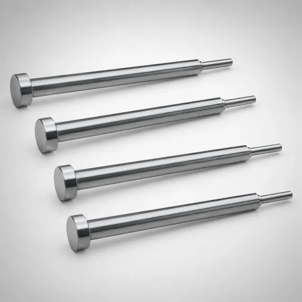
Tip length and reach follow the housing geometry. A short tip of 15 to 25 mm keeps pressure drop low. A 50 mm extended tip reaches a recessed gate but adds 10 to 20 bar of pressure drop, typical figures. Order the tip drawing against the cavity model before the manifold is machined.
Resin Compatibility: PA66 GF30, PBT and LCP
Resin sets the temperature class of the hot half, then the wear and sealing class of the tips.
PA66 with 30% glass. Processing runs 270 to 300 °C typical. Glass fibers are abrasive, so wetted steel should hold 44 HRC or higher. A glass-filled stream can cut a soft channel over 500,000 shots. Worn tips show up as stringing and gate blush before they show up on a gauge.
PBT. Processing runs 230 to 260 °C typical. Viscosity is lower than PA66, filling is easier, and PBT is the forgiving middle ground for hot runners. Keep the resin dry to under 0.02% moisture, because wet PBT hydrolyzes and drops molecular weight.
LCP. Processing runs 330 to 350 °C typical. Viscosity is so low that the melt behaves like water and finds a 0.02 mm gap. Manifold mating faces need precision sealing, channels need Ra 0.2 polish, and every component must be rated for 350 °C. Many shops keep a dedicated LCP hot half instead of purging between programs.
LCP: the leak test your manifold must pass
Every LCP hot runner gets a cold leak check at assembly. Pressurize the channels with air at 6 to 8 bar and hold for 60 seconds with zero drop. Then heat-soak to 350 °C and recheck. Plan seal maintenance every 100,000 to 200,000 shots, because LCP creeps through steel-to-steel fits over time.

The leak check repeats at every mold service, not just at build. A hot half that passed at 350 °C can leak after 200,000 shots of thermal cycling. Include the check in the mold maintenance schedule.
Thermal Balance and Zone Control
Thermal balance is the difference between a 64-cavity mold that runs and one that fights you. Hold ±2 °C at every nozzle tip in steady state, and cavity-to-cavity viscosity stays close enough that flow imbalance stays under 5%.
Zone count scales with drops. An 8-cavity mold runs 4 to 8 zones. A 16-cavity mold runs 8 to 16. A 64-cavity mold runs 16 to 32, because cavities on the same manifold branch share one thermal zone. Each zone needs its own thermocouple, heater and controller channel.
Thermocouple placement matters more than count. Mount the sensor 5 to 8 mm from the nozzle tip bore, not on the heater band. A band-mounted sensor reads 15 to 25 °C hotter than the melt and lags the tip by 30 to 60 seconds. Type J thermocouples are standard for PA66 and PBT. Type K covers LCP-rated systems above 350 °C.
Dead zones kill balance. Support pillars and vent slots in the hot half plate steal heat locally. A 6 mm pillar can drop the plate 8 to 12 °C at that point. Model the hot half thermally before cutting steel. Verify with a thermal camera at first heat-up.
Manifold Block Material and Machining
Manifold steel is a wear and corrosion decision, not a cost line to minimize.
Steel classes. H13 (X40CrMoV5-1) hardened to 44 to 48 HRC handles PA66 GF30 and PBT. Grades 1.2343 and 1.2344 are the European equivalents. P20 at 28 to 32 HRC works for unfilled resins below 250 °C but wears fast with glass. S136 at 48+ HRC resists corrosion for halogenated flame-retardant compounds.
Channel machining. Flow channels are milled on 5-axis machines and polished to Ra 0.4 for standard resins and Ra 0.2 for LCP. Channel diameter for 2 to 15 g parts runs 8 to 16 mm. Keep internal radii at 2 mm or larger so material does not hang and degrade. Grind the parting faces after heat treat to hold flatness within 0.01 mm per 300 mm. That keeps the steel-to-steel seal tight enough for LCP.
Machining the flow channels
Channel sequence: rough mill, stress-relieve at 550 to 600 °C, semi-finish, then polish. Flow length per drop stays under 300 mm for PA66 and PBT and under 200 mm for LCP, because pressure drop scales with length. A 300 mm channel at 8 mm diameter adds about 40 to 60 bar of pressure drop, typical figures. DieStrike holds mold dimensions to ±0.005 mm and part geometry to ±0.002 mm on this class of work.
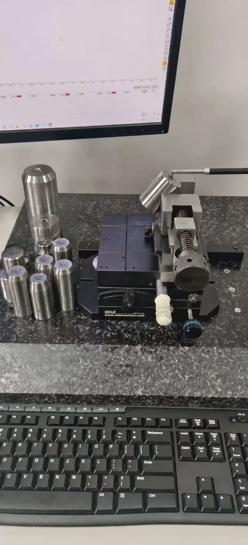
The finish pass decides resin compatibility. A Ra 0.4 channel runs PA66 and PBT without hang-up. A Ra 0.2 channel handles LCP. Measure every channel with a profilometer at first article inspection, and keep the report with the mold file.
Thermal Expansion and Plate Design
A hot half moves when it heats, up to 2.35 mm on a 700 mm plate. Design for that movement or the mold fights itself. Buyers treat the hot runner as a bolt-on module. Toolmakers treat it as a thermal machine with its own displacement budget.
Expansion math: a 400 mm plate grows 1.34 mm
Steel grows about 12 × 10⁻⁶ per °C, with a typical range of 11.5 to 13 × 10⁻⁶. A 400 mm manifold plate heating from 20 to 300 °C grows 1.34 mm. A 700 mm 64-cavity hot half plate grows 2.35 mm. If the plate cannot slide, that growth bows the mold base or shears the locating pins.
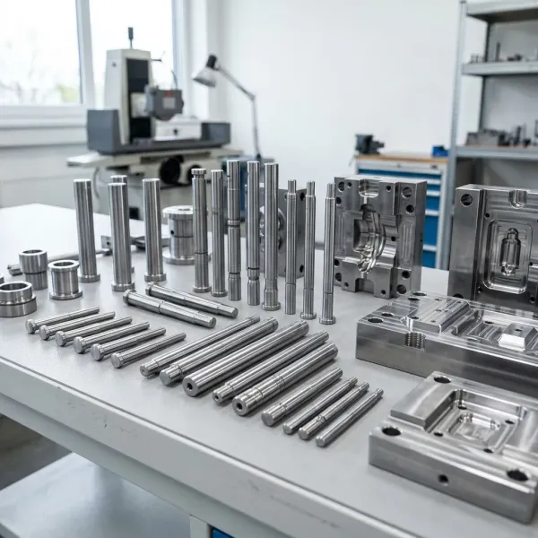
Design rules: mount the manifold on sliding supports with a 6 to 10 mm air gap. Locate the plate from a fixed center and let it grow outward. Insulation plates under the hot half cut heat loss into the cavity plate. A 5 mm ceramic plate cuts it by 60% to 70% versus bare steel contact, typical figures.
Nozzle tip seats move with the plate. Gate inserts must float, or the tip preloads against the cavity and crushes its seat. Use hardened wear plates at 48+ HRC under nozzle seats. Verify tip-to-seat alignment at operating temperature during the T1 trial.
Hot Runner Controller Selection
The controller is the second half of thermal balance. A good manifold with a bad controller drifts 5 to 10 °C.
Specs. Closed-loop PID with ±1 °C readout accuracy is the baseline. Open-loop controllers drift as line voltage and ambient temperature shift. Buy controller headroom: 16 zones for an 8-cavity mold, 32 for a 16-cavity mold, 64 for a 32-cavity mold, because tuning always adds zones.
Protection. A 15 to 30 minute soft-start ramp prevents thermal shock cracking in the manifold. Thermocouple break detection shuts a zone down instead of dumping full power. An over-temperature cutout at 30 °C above setpoint protects an unattended hot half overnight.
Data. Automotive PPAP wants temperature stability records. A controller with Modbus TCP or EtherNet/IP export logs every zone at 1 Hz and proves the ±2 °C claim with data, not anecdotes.
Hot Runner vs Cold Runner: Cost
A hot runner buys two things: cycle time and material. Both are numbers you can run before you order.
Hot runners cut 15% to 40% off cycle time on automotive connector molds, because you skip the sprue and runner cooling segment. A 16-cavity mold at 35 s cold drops to 25 s hot. That is more than 12,000 extra parts per day at 80% utilization. For the full cycle-by-cycle comparison, read our hot runner vs cold runner guide.
Material saving follows. With no cold runner there is no regrind loop, no regrind ratio limit, and 5% to 15% less material. On a 3 g part with a 1.5 g runner, the runner is 33% of every shot. Eliminating it cuts the material bill by a third.
| Cavity Count | Hot Runner System Cost | Cold Runner System Cost | Cycle Saving (Typical) | Payback Window (Typical) |
|---|---|---|---|---|
| 2 | $3,000-$8,000 | $1,500-$4,000 | 10%-15% | 4-8 months |
| 16 | $18,000-$40,000 | $6,000-$15,000 | 20%-30% | 8-14 months |
| 64 | $65,000-$120,000 | $20,000-$45,000 | 25%-40% | 10-18 months |
← swipe to scroll →
Table: typical industry figures; verify against your program.
← swipe to scroll →
Table: typical industry figures; verify against your program.
← swipe to scroll →
Table: typical industry figures; verify against your program.
← swipe to scroll →
Note: Cost ranges are typical industry figures for automotive connector and housing tooling in 2026. Cold runner cost covers the machined cold sprue and runner system in the cavity plate. Payback assumes 24/7 production at 80% utilization.
Payback math
Worked example: 16 cavities, 3 g part, 30 s cold cycle to 21 s hot, 24/7 at 80% utilization. Cold output is 36,864 parts per day. Hot output is 52,663 parts per day, about 43% more capacity on the same press.

At $60 per press hour, that capacity is worth roughly $18,000 a month. The optimistic bound: an $18,000 to $40,000 system pays back in 1 to 3 months. The fully burdened bound, after overhead and maintenance, is the 8 to 14 month window in the table. Plan on the burdened number.
Lead Time and Sourcing
The hot runner is the longest-lead purchased component in the mold. Order it with the mold, not after it.
Custom 16-zone hot runners run 4 to 6 weeks from major suppliers. A 64-drop system runs 6 to 10 weeks, typical figures. DieStrike quotes injection molds at 2 to 4 weeks and standard parts at 3 to 7 days shipping. If you source the hot runner after design freeze, add the full supplier lead to the program.
Integration schedule. Hot half plates, heater pockets and thermocouple holes are machined with the mold. Sequence: hot runner PO at design freeze, manifold arrival before plate finishing, first heat-up at the T1 trial, thermal verification at T2. A 48-hour selection and cost breakdown closes the loop early. DieStrike's injection mold manufacturing service covers hot half integration end to end.
Spares. Buy spare tips, heaters and thermocouples with the system. A nozzle heater costs $80 to $250, typical. Connector line downtime runs $1,000+ per hour, so a $250 spare heater is cheap insurance. DieStrike supplies hot runner systems, sprue bushings and gates with 3 to 7 day shipping on standard items.
The Selection Decision Table
Run the mold through this table before you write the RFQ. Each of the 9 rows is one decision with the reason attached.
| Mold Factor | Choose This | Why |
|---|---|---|
| Annual volume under 2,000,000 parts | 8 cavities, pin-point gates | Lowest tool cost and a 4 to 8 month payback |
| Annual volume 2M to 10M parts | 16 to 32 cavities, H-manifold | Natural balance and press-hour economy |
| Annual volume over 30M parts | 64 cavities, H-manifold or stack | Lowest per-part cost on a locked long run |
| Resin PA66 GF30 | H13 or carbide tips, 44+ HRC wetted steel | Glass fibers erode soft steel within 500,000 shots |
| Resin LCP | Valve gates, Ra 0.2 channels, 350 °C-rated system | Low viscosity leaks through 0.02 mm gaps |
| Cosmetic class-A surface | Valve gate with 2 to 6 mm pin | Near-zero vestige on the mating face |
| Tight footprint, 4 or 8 drops | X-manifold | Short flow path in a compact envelope |
| 24/7 lights-out production | Closed-loop controller, 32+ zones | ±2 °C stability plus thermocouple break protection |
| Tight budget, low volume | Cold runner | No hot half cost when payback never arrives |
← swipe to scroll →
Table: typical industry figures; verify against your program.
← swipe to scroll →
Table: typical industry figures; verify against your program.
← swipe to scroll →
Table: typical industry figures; verify against your program.
← swipe to scroll →
Note: Decision logic for automotive connector and housing molds with 8 to 64 cavities. Volume and cost thresholds are typical industry figures.
FAQ: Hot Runner Selection
Q1. How much does a hot runner add to a 16-cavity connector mold?
A 16-drop hot runner system costs $18,000 to $40,000 (typical), about 10% to 20% of the total mold budget. Cold runner tooling for the same cavity count runs $6,000 to $15,000. The hot runner pays back through 20% to 30% shorter cycles and a 5% to 15% material saving.
Q2. Can one hot runner system run PA66 GF30, PBT and LCP?
Yes, with limits. PA66 GF30 and PBT share the 230 to 300 °C class and work in one system with hardened tips. LCP runs 330 to 350 °C, so it needs a 350 °C-rated system, Ra 0.2 channels and tight seals. A hybrid mold that runs all three needs full purging and a zone re-tune between materials.
Q3. Which manifold is best for 64 cavities?
An H-manifold with 64 drops, because every flow path stays the same length and the system stays naturally balanced. A stack manifold (32 + 32) only makes sense when you want double output per clamp tonnage and the program volume is locked. X-manifolds balance 4-way patterns only.
Q4. How often do hot runner tips need maintenance on glass-filled resin?
On PA66 GF30, plan tip inspection every 50,000 to 100,000 shots and replacement at 300,000 to 500,000 shots (typical). Valve gate pins and seals follow a 100,000 to 200,000 shot interval. Keep spare tips and heaters in stock, because line downtime runs $1,000+ per hour.
Q5. How long does a hot runner mold take to build?
DieStrike quotes injection molds at 2 to 4 weeks. The hot runner system itself adds 4 to 10 weeks of supplier lead time for custom 16 to 64 zone units. Order the hot runner at design freeze, not after, or the program absorbs the full supplier lead.
The Final Call
The wrong hot runner shows up as imbalance, scrap and launch delays, and it shows up late. DieStrike builds IATF 16949 certified molds at ±0.005 mm, with 120+ machines and 24-hour DFM feedback. Selection advice and cost breakdown land in 48 hours. Send us your part drawing, and get a hot runner recommendation with a full cost breakdown within 48 hours.
KEEP READING
Related Reading
5 Mold Cooling Channel Design Tips for Faster Cycles
Mold maker's 5 cooling channel design rules: channel-to-cavity distance 2-2.
Read articleArticle5 Shrinkage Compensation Rules for Mold Design
Shrinkage compensation decides mold accuracy. Five rules: material rates from 0.3% to 2.
Read articleArticle5 Ways to Reduce Mold Cost Without Cutting Quality
Five proven ways to reduce injection mold cost without cutting quality: DFM before quoting, right-sized cavity count,…
Read articleArticle7 Gate Design Best Practices for Balanced Filling
Mold maker's 7 gate design rules for balanced multi-cavity filling: gate depth 50-80% of wall thickness, land 0.5-1.
Read articleNEXT STEP
Ready to Start Your Mold?
Send us your element dimensions or part numbers — our team responds within 24 hours with pricing and lead time.

Written by
Ray ChanMold Buyer's Guide Author · Precision Mold Manufacturing Specialist. Ray helps global importers, distributors and OEMs source factory-direct molds and mold parts.