
How to Select Hot Runner Nozzles: Open Gate vs Valve Gate
Table of Contents
A connector mold ran 40,000 shots with open gate nozzles before the buyer noticed the problem. Every housing carried a 1.2 mm gate blush ring and a 3 mm string of frozen melt. The customer rejected 6,000 parts at incoming inspection. The fix was a nozzle retrofit: valve gate tips, new nozzle bodies, revised pocket depths. The mold was out of production for 9 days and the retrofit cost about 2.5x the original nozzle line item. None of that shows up in a mold quote unless the nozzle type is specified correctly at design freeze.
The nozzle is the smallest component in a hot runner system, and it touches the part directly. It sets gate vestige, stringing, pressure drop, fill balance and maintenance interval. Open gate nozzles cost less and run free of moving parts. Valve gate nozzles cost 2-3x more per nozzle but deliver a clean, repeatable gate. This guide covers component-level selection: architectures, gate quality, materials, actuation, heating, layout fit, wear and cost. For manifold and system-level sizing, see our guide on choosing a hot runner for multi-cavity automotive molds.
The Snapshot
- Cost gap: valve gate nozzles run 2-3x the price of open gate nozzles, plus actuation hardware at roughly USD 300-900 per nozzle for pneumatic cylinders and USD 1,500-4,000 per nozzle for servo-driven pins.
- Gate vestige: open gates leave a 0.8-1.5 mm witness with a visible ring on glossy surfaces. Valve gates leave a flat witness typically under 0.5 mm with no ring.
- Pressure loss: a valve pin inside the nozzle flow channel raises pressure drop by roughly 20-40% versus an open tip of the same diameter, typical industry figures.
- Wear life: standard valve pins survive 1-3 million shots in unfilled resins. With 30% glass fiber, uncoated pins can show measurable wear under 500,000 shots. Hardened or coated pins extend that 2-5x.
- Thermal control: nozzle heaters hold melt within ±1-2°C of setpoint when tuned. A drooling open gate on POM or LCP can waste 0.5-2 grams per shot at the gate.
The Three Hot Runner Nozzle Architectures
Every hot runner nozzle falls into one of three architectures. The choice narrows everything downstream: gate design, controller zones, maintenance plan and spare parts list.
Open gate (open tip). The melt channel runs straight to the gate with no moving parts. A thermal gate forms at the gate orifice when injection stops, typically 0.3-0.8 mm of frozen melt that remelts at the next shot. Open nozzles are the cheapest, run the lowest pressure drop and never fail mechanically. Their weakness is the gate itself: vestige, stringing and drool on low-viscosity resins.
Spring-gated (self-sealing). A spring-loaded check mechanism closes the gate during pack and hold, then opens on injection. Spring-gated nozzles reduce drool and improve gate cosmetics versus a plain open tip. They cost roughly 1.3-1.8x an open nozzle. The spring is a wear item, with typical life of 0.5-2 million cycles before set loss, and spring force decay shows up as slow gate closing and slight drool return.
Valve-gated. A hardened pin slides inside the nozzle and mechanically closes the gate on a timed signal. Valve gates produce the cleanest witness, eliminate stringing at the source and allow sequential opening for fill balance. They cost 2-3x an open nozzle before actuation hardware. Every valve nozzle adds a pin, a guide, a seal, an actuator and a control signal to maintain. Valve gates dominate automotive, medical and cosmetic parts. Open gates dominate packaging, commodity housings and high-cavity molds where 32 gates make valve hardware uneconomical.

Thermal tip versus sprue-bushing style
Within each architecture, nozzles come as thermal-tip or sprue-bushing style. A thermal tip nozzle feeds directly into the cavity through a small heated orifice, usually 0.8-2.0 mm. It leaves the smallest vestige and suits small gates on cosmetic surfaces. A sprue-bushing style nozzle feeds a cold slug well or a larger gate land, tolerating bigger gates of 2-6 mm and abrasive resins better. Thermal tips are sensitive to gate freeze timing, often needing 0.5-1.5 seconds longer hold to remelt the thermal gate cleanly. Sprue-bushing nozzles are more forgiving on cycle time but leave a larger witness that needs a secondary operation on cosmetic faces.
Open Gate vs Valve Gate: Six Decisions That Matter
Six questions decide the nozzle type on most molds. Answer them in order at design freeze, before the manifold layout locks.
1. Does the gate sit on a visible surface? If the customer inspects the gate face under 800-1,000 lux light or the part ships unpainted on a Class A surface, valve gate. An open gate ring of 0.8-1.5 mm will read as a defect on gloss surfaces above 60 gloss units.
2. Is the resin stringy? POM, PA, LCP and low-viscosity PP drool and string from open tips. Valve gates cut the string mechanically. If the molder reports gate strings above 2 mm in trials, the nozzle type is the root fix, not process tuning.
3. How many cavities? At 16-64 cavities, valve actuation hardware and maintenance scale badly. A 32-cavity closure mold almost always runs open gates because 32 cylinders and 32 pins cost more than the entire hot runner. At 1-8 cavities with automotive or medical acceptance criteria, valve gates pay back.
4. Do you need sequential fill? Valve gates can open in timed sequence, typically 50-300 ms apart, to steer weld lines and balance fill in large parts. Open gates fire together. If weld line position is a structural requirement, valve gating with sequencing is the only hot runner answer.
5. Is the resin abrasive? Glass-filled resins above 30% GF erode both nozzle tips and valve pins. Abrasive wear favors either hardened valve pins with coatings or sprue-bushing style open nozzles with renewable inserts. Plain open thermal tips in 40% GF nylon wear out in months.
6. What is the maintenance reality? A valve pin seal leaks after 1-3 million shots. An open nozzle has nothing to leak. If the molder runs lights-out weekends with no tooling technician on site, open gates reduce the failure modes to heaters and thermocouples only.
| Parameter | Open Gate Nozzle | Valve Gate Nozzle |
|---|---|---|
| Relative cost per nozzle | 1x baseline | 2-3x, plus actuator |
| Gate vestige | 0.8-1.5 mm witness, ring on gloss | Flat, typically under 0.5 mm |
| Stringing on POM/PA/LCP | Common, 1-5 mm strings | Mechanically cut, near zero |
| Pressure drop vs same-dia open tip | Baseline | +20-40% typical |
| Sequential fill control | Not possible | Yes, 50-300 ms staged |
| Wear items per nozzle | Heater, thermocouple | Pin, guide, seals, heater, TC |
| Pin/seal service life | N/A | 1-3M shots unfilled, less with GF |
| Best fit | High-cavity packaging, commodity parts | Automotive, medical, cosmetic |
← swipe to scroll →
Table note: typical industry figures for hot runner nozzles in the 8-25 mm body range. Actual values depend on supplier, resin and gate size.
Gate Vestige: What Each Nozzle Leaves Behind
Gate vestige is the fingerprint of the nozzle on the finished part. Buyers accept or reject parts on it, and it is set by nozzle geometry, not by process.
Open gate vestige. An open thermal tip freezes a plug of melt in the gate orifice. On reopening, the plug tears and leaves a raised ring around a 0.8-1.5 mm witness. On textured surfaces (VDI 30-40) the ring hides. On polished or glossy surfaces it shows as a halo, and on fiber-filled resins the ring shows fiber orientation swirl. Gate land length matters: a 0.5-1.0 mm land gives cleaner freeze-off than a zero-land tip.
Valve gate vestige. The pin closes flush with the cavity surface, so the gate freezes as a flat disc. The witness is typically under 0.5 mm with no ring. Pin tip geometry fine-tunes the result: a conical pin tip leaves the smallest mark, a flat tip leaves a slightly larger but more predictable disc. On Class A automotive surfaces, valve gates hold vestige height under 0.05 mm when the pin seats against a hardened, lapped gate insert with flatness within 0.002 mm.
Spring-gated vestige. Spring-gated nozzles land between the two: a 0.5-1.0 mm witness with a faint ring, better than open, not as flat as valve. They suit mid-tier consumer housings where a small gate mark is acceptable but strings are not.
Measurement discipline. Specify vestige acceptance in the drawing, not verbally. Typical specs: height under 0.05 mm, diameter under 1.0 mm, no ring visible at 500 mm under 1,000 lux. First article inspection at T1 should record vestige with a profile projector or CMM, with gate witness height and diameter logged per cavity.

Stringing and Drool: Material-Driven Nozzle Choice
Stringing happens when melt follows the nozzle back out of an open gate during mold opening. Drool happens when melt leaks from the tip during idle. Both are material physics, and the nozzle architecture is the only durable fix.
Why some resins string. Low melt viscosity and high crystallization speed are the triggers. POM (Delrin) is the classic case: its melt unzips and pulls strings of 1-5 mm every shot. PA6 and PA66 string at melt temperatures above 270°C with hot tips. LCP is thin as water at 0.5 mm sections and leaks through any open orifice during pack. PP and PE with MFI above 25 g/10 min drool at tips held above 220°C for more than 60 seconds idle.
The open gate workaround and its limits. Process fixes exist: suck-back of 0.5-2 mm, lower tip temperature by 5-10°C, shorter decompression. Suck-back helps on PP but often starves the gate on crystalline resins and causes short shots. On POM, no process window reliably kills strings above 2 mm. When trials show consistent stringing, the design answer is a spring-gated or valve-gated nozzle, and retrofitting later costs 3-5x specifying it at design freeze.
Why valve gates end stringing. The pin closes the orifice mechanically before mold opening. Melt cannot follow the pin out because the flow path is shut, not frozen. Residual strings drop to near zero, and the molder can raise tip temperature 5-15°C for better fill without drool penalty. For color-sensitive parts, this also means no burned drool flecks in the next shot.
Drool during idle. Open tips drool when heaters stay on during pauses, leaking 0.5-2 g per shot of degraded melt that blackens in the gate. Valve pins seal the channel during idle. If your press runs with frequent stops over 5 minutes, valve or spring gating keeps the first shot after idle clean.
Pressure Loss, Shear and Fill Balance
The nozzle is the last restriction melt passes through. Its pressure drop decides fill speed at the gate, pack transfer and cavity-to-cavity balance in multi-cavity molds.
Open tip advantage. A straight open channel of 2-4 mm diameter has the lowest pressure loss in the system, typically 5-15% of total injection pressure, industry figures. Thin-wall parts at 0.5 mm sections depend on this margin. If a mold flow study shows fill pressure near 90% of machine capability, an open tip buys back the difference that a valve pin would consume.
Valve pin penalty. The pin occupies the center of the flow channel, leaving an annular gap of 0.5-1.5 mm. That raises nozzle pressure drop by roughly 20-40% versus the same body with an open tip. On a 1,200 bar machine this can mean 40-120 bar lost at the gate. Specify valve gates with a slightly larger body or accept slower fill, and verify with mold flow analysis before design freeze.
Shear and material degradation. The annular gap raises shear rate. On shear-sensitive resins like PVC, flame-retardant PC/ABS and some LCP grades, high nozzle shear causes degradation, splay and black specks. If the resin data sheet limits shear rate below 100,000 1/s, prefer open or spring gates, or a valve gate with a generous annular gap above 1.0 mm.
Cavity balance. In multi-cavity molds, nozzle-to-nozzle variation must stay within ±2% of fill weight for a balanced fill, a typical automotive acceptance criterion. Valve gates allow post-process correction through staggered open timing in 10-50 ms steps. Open gate molds need geometric balance from the manifold instead. When you cannot afford a fully balanced manifold, sequential valve gating is the correction tool.

Valve Pin Actuation: Pneumatic, Hydraulic and Servo
A valve gate is only as good as its actuation. Three drive types dominate, and the choice affects mold complexity, timing precision and service life.
Pneumatic cylinders. The most common drive, mounted on the mold platen or inside the manifold plate. Operating pressure is 5-7 bar, stroke 10-30 mm, actuation time 30-80 ms per pin. Cost is roughly USD 300-900 per nozzle including the cylinder and fittings. Pneumatics suit molds up to 8-16 pins where plant air is stable at ±0.3 bar. Their weakness is speed drift with air pressure variation, which shifts gate open timing by 10-20 ms and can unbalance sequential fill.
Hydraulic cylinders. Used on large automotive molds with 4-20 pins, or where mold-mount air is unavailable. Operating pressure 60-140 bar gives faster, more consistent actuation, 20-50 ms per stroke. Cost runs USD 800-2,000 per nozzle plus a hydraulic power unit. Hydraulics handle long pin strokes above 30 mm and heavy timing loads better than pneumatics. The added service is leak control: one dripping hose fitting can contaminate a cavity and scrap parts until it is found.
Servo-driven pins. An electric servomotor drives each pin or a pin bank through a cam or ball screw. Position control reaches ±0.01 mm and timing resolution of 1 ms, versus 10-30 ms for pneumatics. Cost is USD 1,500-4,000 per nozzle plus controller. Servo actuation enables partial-lift gating, where the pin opens 0.3-1.0 mm to slow initial fill and eliminate jetting, then full-lift for pack. On thin-wall and cosmetically critical parts, servo valves are the premium answer. They also remove all air and oil plumbing from the mold.
Timing and control integration. Whatever the drive, pin actuation needs a signal from the press cycle, usually via the hot runner controller with inputs from mold-open and injection-start signals. Sequential timing windows of 50-300 ms between pins are standard for automotive body panels. Specify the control interface in the RFQ so the hot runner supplier and press integrator agree before build.
Nozzle Heating: Coil Heaters and Torch Tips
Nozzle heaters keep melt at processing temperature from manifold to gate. Heater selection decides thermal uniformity, ramp time and service life.
Coil heaters. A resistance wire coil wrapped around or cast into the nozzle body. Typical power density is 3-8 W/cm² of nozzle surface, holding melt within ±1-2°C of setpoint when the controller is tuned. Coil heaters are field-replaceable in 15-40 minutes per nozzle and cost USD 50-250 each. Life is 8,000-20,000 heating hours, with burnout concentrated at the gate end where thermal cycling is hardest. On a 6,000 hour per year mold, plan one heater change every 1.5-3 years per position.
Torch tips (braze-in heaters). The heater element is brazed directly into the nozzle tip, giving the fastest thermal response and the tightest gate temperature control, ±1°C typical. Torch tips suit small nozzles under 12 mm body diameter and fast cycles under 8 seconds where tip freeze-off risk is high. The tradeoff is service: a failed brazed tip usually means replacing the whole nozzle, USD 200-800, rather than a USD 80 coil. Specify torch tips when cycle speed demands them and budget nozzle-level spares instead of heater-level spares.
Thermocouple placement and type. Each nozzle needs its own thermocouple, J-type up to 700°C or K-type to 1,200°C. Placement 3-5 mm from the gate tip reads true melt temperature. A thermocouple near the heater band reads heater temperature, not melt, and drifts 5-15°C from reality. Tolerant-loop thermocouples survive vibration better in high-cavity molds. At T1 trial, verify each zone against a calibrated probe, a check included in our hot runner maintenance checks.
Thermal expansion in the mold. A 200 mm long nozzle at 250°C grows roughly 1.2 mm from room temperature, using 12 µm/m°C for tool steel. The nozzle pocket and manifold interface must absorb this growth through floating seats or expansion gaps. A nozzle that is rigidly clamped cold will bow or leak when hot, and leakage between nozzle and manifold is the number one hot runner failure at startup.

Matching Nozzle Length and Spacing to Cavity Layout
Nozzle geometry must fit the mold, not the other way around. Length, body diameter and gate pitch constrain cavity layout, cooling lines and plate thickness.
Nozzle length equals plate stack. The nozzle body spans from manifold to cavity, so its length matches mold stack height: manifold plate, nozzle spacer, cavity plate, typically 60-250 mm total. Every 10 mm of extra length adds a flex and thermal growth risk. Keep nozzle length under 150 mm where possible, and above 200 mm specify a guided or supported nozzle body to prevent deflection under clamping load of 100-500 tons.
Body diameter and pitch limits. Standard nozzle bodies are 14, 18, 22 and 25 mm diameter. Cavity pitch must exceed body diameter plus 4-6 mm clearance for heater wiring and thermal isolation. A 22 mm body needs 26-28 mm minimum pitch. In a 16-cavity mold at 30 mm pitch, the cavity field spans about 150 mm per row, which then sets manifold length and platen coverage. When part geometry demands tighter pitch than 26 mm, step down to a 14-18 mm body or move to valve-in-valve compact nozzles.
Gate location versus part geometry. The nozzle fixes where melt enters. On annular parts, a nozzle gating to the center needs a torpedo or sprue-bushing style tip. On long thin parts, a single edge gate works with an open tip. When gate location fights cavity pitch, the manifold layout decides: inline nozzles keep pitch simple, while offset manifolds with nozzle drops allow gates off the cavity centerline. Model both options in mold flow before committing.
Cooling clearance. Nozzle bodies radiate 150-300°C of heat into the surrounding plates. Cooling lines must stay 8-12 mm away from the nozzle pocket to avoid freezing the gate, but close enough to protect mold steel. This dead zone shrinks usable cooling area by 15-25% around each gate. In high-cavity molds, conformal cooling or beryllium-copper inserts around the nozzle pocket recover cycle time.
Wear and Material Compatibility: GF, LCP, POM
Resin chemistry and filler decide nozzle tip material and valve pin life. Match them at specification time, not after the first wear-out.
Glass-filled resins above 30% GF. Glass fibers cut and erode flow surfaces. Standard H13 tips at HRC 48-52 wear visibly under 500,000 shots in 30-50% GF nylon or PBT. Specify hardened nozzle tips at HRC 58-62, or tungsten-carbide inserts, or DLC-coated pins with hardness above 2,000 HV and friction coefficient under 0.15. A DLC-coated valve pin lasts 2-5x an uncoated one in abrasive service, which makes coating mandatory above 30% GF.
Valve pin materials. Standard pins are tool steel at HRC 50-55. For abrasive resins, specify HRC 58-62 hardened or carbide-tipped pins. Pin-to-guide clearance runs 0.01-0.03 mm cold. As the guide wears, clearance grows past 0.05 mm and melt leaks past the pin, leaving flash rings on the gate. Measure guide clearance at every preventive maintenance interval, typically every 250,000-500,000 shots.
LCP and low-viscosity resins. LCP leaks through clearances above 0.005 mm and flashes easily. Open gate nozzles with a tight thermal gate, 0.5-1.0 mm orifice, seal LCP by freeze-off better than valve pins, whose sliding clearance is a leak path. If a valve gate is mandatory for cosmetics, specify pin-to-guide clearance at the low end, 0.01 mm, and plan seal replacement every 1-2 million shots.
POM and acid-generating resins. POM releases formaldehyde at melt temperatures above 225°C, and flame-retardant grades release corrosive byproducts. Specify corrosion-resistant nozzle steels such as stainless-treated or coated bodies, and avoid copper alloys in the melt path. POM also needs open or valve gates with generous suck-back control, since its crystallization speed freezes thermal gates in under 0.5 seconds.
Color-sensitive and transparent parts. Any degraded melt fleck shows in a clear lens or a light-gray housing. Valve gates win here: no drool means no burned material carried into the next shot, and sequential opening keeps shear heat down. For transparent PC and PMMA, specify polished flow channels at Ra 0.2 or better and torch-tip heating for tight gate temperature control within ±1°C.
Maintenance, Spares and Nozzle Life
Nozzle maintenance cost is a design decision. Count the wear items each architecture adds, then decide whether the gate quality is worth them.
Wear item count. An open nozzle has 2 service items: heater and thermocouple. A spring-gated nozzle adds a spring and a check seat, 4 items. A valve nozzle adds pin, guide bushing, seals and actuator, 6-7 items. Multiply by cavity count: a 4-cavity valve mold carries about 24 service items in the nozzle zone alone.
Typical service intervals. Heaters: 8,000-20,000 heating hours. Thermocouples: 1-3 years or on drift above ±5°C. Valve pins and guides: inspect at 250,000-500,000 shots, replace at 1-3 million shots unfilled. Seals: replace with the pin. Springs in spring-gated nozzles: 0.5-2 million cycles. Keep spares at 100% of heaters and thermocouples, 25-50% of pins and seals, and one full actuator per mold family.
Leak testing at assembly. After any nozzle service, heat the system to processing temperature and hold 30 minutes before molding. Watch the nozzle-to-manifold joint and the pin guide for melt weeping. A single leak drops 1-5 grams per shot onto the mold face and bakes into a defect. Treat leak-down testing as a release gate before the mold returns to production.
Spare part standardization. Where production spans multiple molds, standardizing nozzle bodies across projects cuts spares cost by 30-50%. A 22 mm body family sharing heaters, thermocouples and pins across three molds needs one spares kit, not three. Specify the supplier and body size in the mold standard, the same way mold bases are standardized.
Cost Accounting: What Valve Gates Really Add
The nozzle price gap is only the visible part of the cost. Count the full delta before deciding, both at build and over the mold life.
Build cost delta. For a 4-cavity mold, open gate nozzles run roughly USD 200-600 each. Valve gate nozzles run USD 600-1,800 each before actuation. Add pneumatic cylinders at USD 300-900 per pin, or servo drives at USD 1,500-4,000 per pin. The 4-cavity valve conversion typically adds USD 4,000-12,000 to the hot runner package, about 3-8% of total mold cost on a mid-size tool. Mold plate machining also grows: valve actuation needs cylinder pockets and pin guide bores held within ±0.01 mm, adding 8-16 hours of CNC and EDM work.
Lifetime cost delta. Over 3 million shots, a 4-valve mold consumes about 4 pins, 4 seal kits and 1-2 actuators in spares, roughly USD 2,000-5,000. An open gate mold consumes heaters and thermocouples only, roughly USD 500-1,500. The valve side also needs 4-8 hours of scheduled downtime per pin change versus under 1 hour for a heater swap.
What valve gates return. The payback comes from yield and secondary operations. Parts with gate strings or blush rings need 100% inspection or manual trimming at USD 0.02-0.10 per part. On a 3 million shot program, trimming alone costs USD 60,000-300,000, which dwarfs the USD 4,000-12,000 build delta. If the gate is on a visible surface or the resin strings, valve gates pay back inside the first year. If the gate is hidden and the resin behaves, open gates are the cheaper honest choice. Our cost structure breakdown is in the guide on how to budget an injection mold.
The 12-Point Nozzle Selection Checklist
Run this checklist at design freeze with the mold designer, the molder and the hot runner supplier in the same meeting. Every "yes" needs an owner and a number in the mold specification.
- 1. Gate visibility class. Cosmetic (valve), functional (open or spring), hidden (open).
- 2. Vestige spec. Written on the part drawing: height, diameter, ring visibility under defined lux.
- 3. Resin stringing behavior. POM, PA, LCP above 2 mm strings in trials means valve or spring gate.
- 4. Cavity count and pitch. Pitch must exceed nozzle body diameter plus 4-6 mm; above 16 cavities prefer open gates.
- 5. Pressure loss budget. Valve pins add 20-40% nozzle pressure drop; verify fill margin in mold flow.
- 6. Sequential fill need. Weld line placement or fill balance correction requires valve gates with 50-300 ms timing.
- 7. Filler content. Above 30% GF specify hardened tips HRC 58-62, carbide inserts or DLC-coated pins.
- 8. Actuation type. Pneumatic for up to 16 pins, hydraulic for heavy timing, servo for partial lift and ±0.01 mm control.
- 9. Heater type. Coil heaters for serviceability, torch tips for cycles under 8 seconds and tips under 12 mm.
- 10. Thermal expansion allowance. Floating seats or expansion gaps sized for 1.0-1.5 mm growth on 150-250 mm nozzles at 250°C.
- 11. Spares list. 100% heaters and thermocouples, 25-50% pins and seals, one actuator per mold family.
- 12. Supplier standardization. Same nozzle body family across the mold platform to cut spares cost 30-50%.
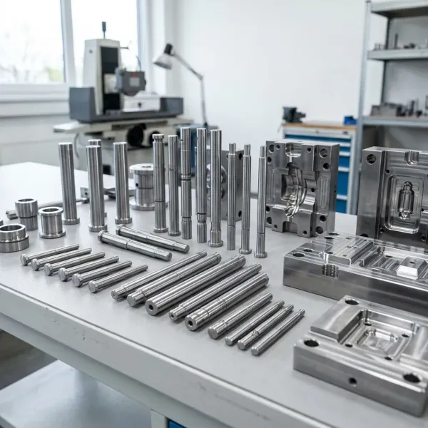
DieStrike builds molds around these decisions daily for connector OEMs including TE Connectivity, Amphenol and Luxshare. Nozzle pockets and gate inserts are machined to ±0.005 mm on mold dimensions and ±0.002 mm on component geometry, with DFM feedback on nozzle selection returned within 24 hours of RFQ. Injection molds ship in 2-5 weeks, and replacement hot runner standard components leave the shelf in 3-7 days.
FAQ: Hot Runner Nozzle Selection
Q1. When is a valve gate nozzle worth the 2-3x cost?
When the gate sits on a visible surface, the resin strings (POM, PA, LCP), or you need sequential fill for weld line control. On a 3 million shot program, eliminating manual gate trimming at USD 0.02-0.10 per part returns the USD 4,000-12,000 build delta many times over. For hidden gates on well-behaved resins, open gates are the correct economic choice.
Q2. Can I convert an open gate mold to valve gate later?
Technically yes, but expect 3-5x the cost of specifying valves at design freeze. Conversion needs new nozzle bodies, actuator pockets in the manifold or backing plates, revised cooling around the pockets, and 5-10 days of mold downtime. The mold must also have steel remaining around the gate: valve nozzles are larger, and a pocket that consumed the margin blocks conversion entirely.
Q3. How long does a valve pin last in glass-filled resin?
Standard tool steel pins at HRC 50-55 show measurable wear under 500,000 shots in 30-50% GF resins. Hardened pins at HRC 58-62, carbide-tipped pins or DLC-coated pins extend life 2-5x, reaching 1-3 million shots. Inspect pin-to-guide clearance every 250,000-500,000 shots and replace when clearance exceeds 0.05 mm.
Q4. Which heater is better for a fast-cycle mold?
For cycles under 8 seconds and nozzle bodies under 12 mm, torch tips hold the gate at ±1°C and resist freeze-off best, but a failed tip means a full nozzle replacement at USD 200-800. For slower cycles and serviceability, coil heaters at ±1-2°C cost USD 50-250 and swap in 15-40 minutes. Many production fleets standardize on coil heaters and carry 100% heater spares.
Q5. How many nozzles can one controller zone handle?
One zone per nozzle is the standard for thermal control within ±1-2°C. Some controllers group two identical nozzles on one zone in high-cavity molds to cut cost, but any nozzle-to-nozzle variation then shows up as fill imbalance of 3-8%. On automotive and medical molds, specify one zone per nozzle without exception.
The Bottom Line
Nozzle selection is a gate-quality decision made at design freeze. Open gates win on cost and uptime for high-cavity and hidden-gate molds. Valve gates win on vestige, stringing and fill control for automotive, medical and cosmetic parts. Wrong choices surface as rejected lots, and retrofits cost 3-5x. Specify the twelve checklist points in writing, and have your toolmaker verify them in DFM before steel is cut. If you want a nozzle selection review on your next mold, talk to our engineering team.
KEEP READING
Related Reading
How to Choose a Hot Runner for Multi-Cavity Automotive Molds
System-level hot runner selection for multi-cavity automotive tooling, from manifold sizing to thermal balance.
Read articleArticle7 Hot Runner Maintenance Checks Before Every Run
Pre-run checks that catch heater failure, nozzle leakage and thermocouple drift before they scrap parts.
Read articleArticle7 Gate Design Best Practices for Balanced Filling
Gate sizing, location and balance rules that decide fill pattern, weld lines and cosmetic quality.
Read articleServiceInjection Mold Manufacturing
IATF 16949 injection mold building with ±0.005 mm accuracy and 2-5 week lead times.
Read articleNEXT STEP
Ready to Start Your Mold?
Send us your element dimensions or part numbers — our team responds within 24 hours with pricing and lead time.

Written by
Ray ChanMold Buyer's Guide Author · Precision Mold Manufacturing Specialist. Ray helps global importers, distributors and OEMs source factory-direct molds and mold parts.