
How to Design Ironing Dies: Wall Thinning, Radius and Lubrication
Table of Contents
An ironing stack that runs 0.03 mm over clearance shaves a can wall to 0.09 mm and splits the body inside the first 40,000 cans. Reworking three rings and re-qualifying the line costs USD 18,000 to 30,000 and 8 to 12 days of output. Ironing is the operation that pushes a drawn cup through a ring whose bore is smaller than the wall, so the metal thins and flows into height instead of tearing.
This guide covers reduction windows, die stack geometry, wall map math, ring finish, lubrication rates, ring materials and ultrasonic inspection for aluminium and tinplate can and cup lines.
The Snapshot
- 0.15 to 0.55 mm wall per pass. AA3004 aluminium and tinplate take 10 to 25 percent of the incoming wall per pass, so a body-maker stack runs four to six rings and a redraw runs one.
- 95 to 105 percent clearance. The ring bore is set against the target wall, not the incoming wall, so 1 to 4 percent springback lands the finished thickness on size.
- Ra 0.1 to 0.2 micron land. The ironing land carries the whole load, and a 0.005 mm steel inclusion alone prints a score line on every can that follows it.
- 1 to 3 g/m2 oil film. A food-grade or post-washable lubricant at that rate holds pickup away; a starved land reaches 150 to 250 °C and welds metal to the ring.
Why Ironing Breaks the Draw-Die Rules
A deep draw adds wall material from the flange. The blank holder controls flow, the draw radius controls the bend, and the wall leaves the die close to the thickness of the blank. Deep draw die design stops at that point.
Ironing does the opposite. No new material enters the wall. The ring bore is smaller than the cup, so the punch forces the wall through a reduced gap and the surplus metal is transferred into length. Volume is conserved inside 1 to 2 percent, so every 0.10 mm of wall removed adds roughly 8 to 12 mm of height on a 66 mm body.
One change moves the design discipline from force control to geometry control. A draw die is tuned with blank-holder pressure and draw-bead height. An ironing die is set by ring bore, clearance and land finish, and those numbers live in hardened steel.
Ironing also multiplies every error the draw leaves behind. A cup that arrives 0.02 mm thick in one angular band passes through four rings, and if each ring takes 20 percent that same band leaves 0.033 mm under target. A wall map of the incoming cup therefore comes before any ring is ground.
The Ironing Stack: Punch, Ring and Clearance
A body-maker ironing stack runs four to six passes. The punch carries the cup through a series of hardened rings, each one smaller than the last, and a bottom-forming or dome station closes the body. A redraw line applies one ironing pass to trim the wall by 0.15 to 0.30 mm.
Clearance is the controlling dimension. On each ring, clearance is the radial gap between the ring bore and the punch surface. Set it at 95 to 105 percent of the target wall, because the wall springs back 1 to 4 percent after the ring and lands on size. A target wall of 0.120 mm therefore runs a ring bore that leaves 0.114 to 0.126 mm of metal once elastic recovery is done.
The punch nose carries a radius of 0.4 to 1.5 mm. A tight 0.4 to 0.6 mm radius suits a small cup of 30 to 50 mm diameter with a short wall. A long body of 150 to 250 mm wants 0.8 to 1.5 mm so the metal bends into the first ring without a crease.
Every ring sits in a retainer plate on a 0.01 mm concentricity budget. A ring 0.02 mm off center shaves one side of the cup more than the other, and the error closes into an oval section that fails the ultrasonic wall check.

Reduction Window and Pass Counting
Each pass removes a controlled slice of wall. The working window is 10 to 25 percent of the incoming wall per pass. On typical stock that equals 0.15 to 0.55 mm on a first pass and 0.02 to 0.05 mm on a finishing pass.
Below 10 percent the ring rubs the wall without a clean reduction. The surface work-hardens, the metal brightens and no useful height is gained. Above 25 percent the tensile load at the ring exit passes the flow stress of the alloy, and the wall tears at the shoulder.
Aluminium alloy AA3004 and electrolytic tinplate hold the widest window and are the standard body materials. AA3004 takes a first pass of 20 to 25 percent reduction and 10 to 15 percent on later passes. Tinplate of 0.20 to 0.30 mm runs slightly lower reduction because the coating limits strain.
| Ironing pass | Incoming wall (mm) | Wall reduction (%) | Outgoing wall (mm) | Ring clearance vs target |
|---|---|---|---|---|
| 1 coarse | 0.300 | 22 to 25 | 0.225 to 0.234 | 95 to 100 percent |
| 2 | 0.234 | 18 to 20 | 0.187 to 0.192 | 95 to 100 percent |
| 3 | 0.192 | 15 to 18 | 0.157 to 0.163 | 98 to 103 percent |
| 4 | 0.163 | 12 to 15 | 0.139 to 0.143 | 100 to 105 percent |
| 5 finish | 0.143 | 10 to 12 | 0.126 to 0.129 | 100 to 105 percent |
← swipe to scroll →
Table note: wall values are typical for an AA3004 body of 66 mm diameter starting from a 0.300 mm drawn wall. Confirm the pass schedule against the incoming cup wall map and the measured flow curve of the alloy.
Count the passes from the required total reduction, not from habit. A cup that must fall from 0.300 mm to 0.120 mm needs a 60 percent total reduction, which no single ring can carry. Split it as 24, 20, 17, 14 and 11 percent and no single pass leaves the 25 percent safe ceiling.

Wall Map Math: Base, Body and Rim
A wall map is the finished thickness plotted around the cup at a set of heights. It is the document that proves the pass schedule worked, and it is the first record to pull when a customer reports a light body on the filling line.
The base and dome are never ironed, so they keep the drawn wall of 0.20 to 0.30 mm set by the initial draw. The sidewall carries the ironing, and after a four-pass stack it lands at 0.10 to 0.15 mm depending on the alloy and the target can weight.
The metal near the rim has passed through every ring, so it carries the accumulated reduction and forms the thinnest zone of the body. That gradient is deliberate, because the rim is trimmed and flanged while the load-bearing section sits in the middle of the map where the wall is held at the target.
Blank area comes from volume constancy. Finished wall times finished height plus the base area sets the blank diameter inside about 2 percent, and the first draw then sets the starting wall that the rings reduce. Get the blank wrong and one ironing ring either starves on metal or overloads the wall.
Measure the map at 120 degree intervals around the circumference and at no fewer than five heights. Print the numbers against the drawing limit, because a single low reading at one angle is the signature of an off-center punch rather than of a worn ring.
Ring Geometry: Entry Taper, Land and Exit Relief
A ring is three features in one piece: an entry taper, a cylindrical land and an exit relief. Each carries a different load, and each carries its own tolerance.
The entry lead-in taper runs 15 to 30 degrees and blends into the land on a radius of 0.3 to 0.8 mm. The taper seats the cup wall without scuffing the surface as it enters. A shallow taper of 15 degrees needs a longer axial nest and loads the metal gently. A steep 30 degrees shortens the stack but raises contact pressure at the entry.
The land is the working zone. Keep it 1 to 3 mm long. A short land of 1 to 1.5 mm cuts friction and suits a low-viscosity oil. A longer land of 2 to 3 mm guides a thin wall through the ring and holds concentricity, at the cost of more heat and a heavier oil demand.

Behind the land, grind a back relief of 2 to 5 degrees so the wall springs clear instead of dragging. A ring with no relief traps the wall on the exit side, and a black band appears on the next 20,000 cans.
Hold the ironing diameter to 0.002 mm and the roundness to 0.005 mm. A bore that is 0.005 mm out of round produces a 0.010 mm wall spread on a 0.120 mm target. That is 8 percent of the wall before any process variation is added.
Surface Finish and Failure Modes
The ironing land demands Ra 0.1 to 0.2 micron, polished circumferentially in the direction of metal flow. A rougher land of Ra 0.4 micron drags, raises friction and burns the oil film. A land polished below Ra 0.05 micron is too smooth to hold oil and starves just as fast.
Cleanliness is a hard limit. A 0.005 mm steel inclusion, a chip or a burr in the land prints a score line on every can that follows. That line runs the full height of the body. Gauges catch the wall, not the finish, so the score can reach the customer before the map does.
Galling is the second failure mode. Uncoated tool steel picks up aluminium at the land after 20,000 to 50,000 can hits and then tears the wall. The same land with a CrN, TiN or DLC layer runs 200,000 to 1,000,000 hits before a regrind. Anti-galling coatings are the cheapest life extension on the line.
The third mode is tearing at the exit. It points to a reduction above 25 percent, a land radius that is too sharp, or a starved film. The tear usually shows first on the leading edge of the wall, where strain is highest.
Lubrication for Can and Cup Lines
The can line runs 1 to 3 g/m2 of a food-grade or post-washable oil. The film carries the contact load at the land, and its thickness is set by the roller coater or the spray nozzles rather than by an operator's eye.
Too little oil is the common fault. A starved land heats the cup wall to 150 to 250 °C, the boundary film breaks and metal transfers to the ring. The result is a rough, bright, scored band that repeats on every following can.

Too much oil fails in the other direction. A heavy film of 4 g/m2 or more lets the wall hydroplane over the ring without a clean reduction. The bore then floats on oil, the wall misses the target, and a 0.01 mm float error grows into a wrinkle band around the body.
Oil viscosity runs 20 to 60 cSt at 40 °C depending on the pass and the alloy. Roughing passes take the heavier end, while finishing passes take the lighter one, because a thick film on a light reduction causes exactly the hydroplaning of an over-oiled ring.
Keep the oil supply warm and metered. A supply temperature that swings 10 °C changes the film by 15 to 20 percent. On a line running 200 to 400 cans per minute, that swing reaches the land as a pickup inside one shift. Fluid grade selection, whether a chlorinated, soap or wax chemistry, is a separate decision that belongs with the fluid supplier and the waste-treatment plan.
Tooling Materials: M2, M4 and Carbide
M2 and M4 high-speed steel are the default ring materials. Both hold the ironing bore at HRC 62 to 64 in production, take a fine circumferential polish, and resist the adhesive wear that aluminium loads onto bare tool steel.
M4 brings 4 to 5 percent vanadium against roughly 2 percent in M2, which lifts wear resistance at the cost of grinding difficulty. Use M4 on a line running above 300 cans per minute or on a campaign beyond 500,000 hits. Use M2 where the ring must be reground repeatedly and a tougher edge matters more than peak life.
Cemented carbide takes over on campaigns of 50 million cans and above. A tungsten carbide ring holds its diameter for the whole run and is ground to 0.002 mm on the ironing bore. It costs 3 to 5 times an M2 ring, so the case for it rests on the regrind count and the line stoppage rather than on the initial price.
Mount rings by shrink-fit or keyway. A shrink-fit interference of 0.04 to 0.08 mm, about 0.3 percent of the retainer bore, holds the ring true under load. Key or dowel retention suits a ring that must come out for regrind without a hot plate.
Heat treatment discipline decides the life as much as the grade does. Our shop heat-treats to a 62 HRC maximum and holds +/-0.005 mm mold tolerance, with +/-0.002 mm on EDM and jig-grinding. The ring bore and the retainer seat then land together without a shim.
Inspection: Ultrasonic Wall Mapping and Ring Clearance
Wall thickness is measured with an ultrasonic gauge after every ring change and at the start of every run. A contact gauge reads through the metal from the outside, so the cup stays intact and the map builds in minutes.
Take readings at 120 degree intervals at the rim, the mid-body and 10 mm above the base. A wall drift of 0.02 mm against the last approved map means a ring has worn past its limit or the punch has gone off center. The drift is the signal; a single reading inside tolerance is not enough.
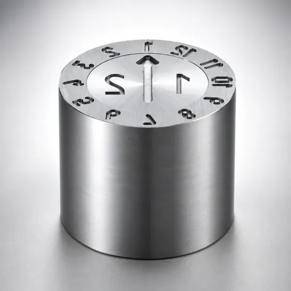
Confirm the punch path with a dial indicator on the punch nose, not with the gauge alone. A punch concentric to 0.005 mm holds the wall spread inside 0.01 mm. A punch at 0.02 mm off center closes the same wall to an oval that fails at the flange. Punch clearance practice follows the same logic on every stamping station.
Check the ring clearance on a surface plate before assembly. Mount the ring on its retainer, sweep the bore with a test indicator at four positions, and record the bore diameter against the drawing. Then compute the clearance to the punch and compare it against 95 to 105 percent of the target wall.
| Check | Target | Method | Action if out |
|---|---|---|---|
| Bore diameter | 0.002 mm of drawing | Bore gauge or CMM at four positions | Regrind or reject the ring |
| Roundness | 0.005 mm max | Roundness tester or indicator sweep | Replace the ring |
| Clearance to punch | 95 to 105 percent of target wall | Bore minus punch diameter | Re-cut the bore or swap the punch |
| Concentricity to retainer | 0.01 mm max | Dial indicator on the mounted ring | Re-seat or re-machine the retainer |
| Land length | 1 to 3 mm | Profile projector or optical scope | Regrind the entry taper |
| Land finish | Ra 0.1 to 0.2 micron | Surface roughness tester, circumferential | Repolish in the flow direction |
| Entry taper and back relief | 15 to 30 degrees, 2 to 5 degrees | Profile projector | Re-cut the lead-in and exit |
| Ring hardness | HRC 60 to 62 shop maximum | Hardness tester at three points | Re-heat-treat or replace |
| Surface defects | No inclusion above 0.005 mm | Visual at 3x plus dye check | Repolish or reject |
← swipe to scroll →
Table note: targets are typical for an AA3004 or tinplate body-maker line. Record every reading against the ring serial number and the punch number so a 0.02 mm drift can be traced to one component.
Redraw Ironing vs Body-Maker Stacks
A redraw ironing tool applies one reduction pass. The cup comes from a first draw, passes a single ring that trims 0.15 to 0.30 mm from the wall, and leaves the press in one stroke. It suits cups, shells and thin-wall tubing where the finished wall is 0.2 to 0.4 mm.
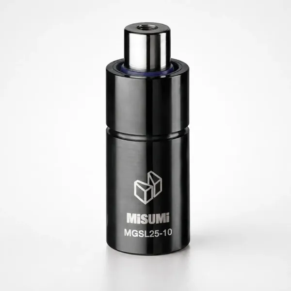
A body-maker stack applies four to six passes in one machine at 200 to 400 cans per minute. Each ring takes a smaller slice, the metal work-hardens less between passes, and the finished wall can reach 0.10 mm. Tooling cost and change-over logic both scale with the pass count.
Brake and clutch cylinders, spark plug shells and thin-wall tubing are ironed parts, and they sit closer to the redraw model than to a can line. A 0.3 mm cylinder wall from a 0.6 mm blank is one heavy pass followed by a light sizing pass, not a five-ring stack.
Choose the stack from the total reduction and the run volume. One pass of 25 percent on a 0.300 mm wall lands 0.225 mm. Reaching 0.120 mm from the same blank needs the five-pass schedule in the table above, and no single heavy pass can substitute for it without tearing the wall.
A new ironing stack is built from the pass schedule and the wall map in 2 to 5 weeks. Standard punch and ring components ship in 3 to 7 days. Stamping die manufacturing delivers the ring, punch and retainer build as one package.
Defect Signatures and Their Numbers
Read the defect and it names the number. A score line that runs the full height points to an inclusion or a burr above 0.005 mm in the land, not to the process.
A wrinkle band at mid-body points to a heavy oil film that lets the wall float, or to a clearance below 95 percent that pulls metal from the base. A bright, rough, circumferential band points to a starved film and a land that has reached 150 to 250 °C.
A split at the shoulder points to a pass above 25 percent reduction. An oval section with a wall spread above 0.01 mm points to a punch off center by more than 0.005 mm, or to a retainer seat out by 0.01 mm.
A wall 0.02 mm thin at one angle and on size everywhere else points to a ring bore worn unevenly or mounted out of round. Orange peel points to excessive work-hardening from too many light passes, where the reduction stays under 10 percent and rubs instead of cutting.
Record every signature with its number. A log that carries the wall reading, the ring serial number and the pass count turns a two-shift fault hunt into a 20 minute ring change.
The Bottom Line
Ironing lives on five numbers. Reduction runs 10 to 25 percent per pass and clearance holds at 95 to 105 percent of the target wall. The land keeps Ra 0.1 to 0.2 micron. The oil film stays at 1 to 3 g/m2, and the wall map holds inside 0.02 mm run to run. Meet those and the wall thins without tearing.
DieStrike builds ironing rings, redraw dies and stamping tooling to IATF 16949, with 120+ machines and +/-0.005 mm mold tolerance. EDM and jig-grinding hold +/-0.002 mm, and hardness runs up to HRC 62. Standard components ship in 3 to 7 days, full tool lead times run 2 to 5 weeks, and tier-1 references include TE, Amphenol, Luxshare and Dongshan.
If a can or cup program is on the roadmap, send the wall target, the alloy and the pass count. We will return a ring schedule and a clearance check before the first ring is ground.
KEEP READING
Related Reading
Deep Draw Die Design: Clearance and Draw Ratio
Blank-holder force, draw radius and reduction ratios that set the cup before any ironing ring touches it.
Read articleArticleAnti-Galling Coatings: CrN, TiN and DLC
Coating thickness and hardness numbers that lift uncoated tool life from 50,000 hits to over a million.
Read articleArticleMaintaining Punch Clearance in Progressive Dies
How clearance drift shows up in burr height, slug pulling and tool load on a running stamping line.
Read articleServiceStamping Die Manufacturing
IATF 16949 die building with +/-0.005 mm mold tolerance, HRC 62 heat treatment and 2 to 5 week lead times.
Read articleNEXT STEP
Ready to Start Your Mold?
Send us your element dimensions or part numbers — our team responds within 24 hours with pricing and lead time.

Written by
Ray ChanMold Buyer's Guide Author · Precision Mold Manufacturing Specialist. Ray helps global importers, distributors and OEMs source factory-direct molds and mold parts.