
How to Design Molds for EV Busbar Overmolding
Table of Contents
A 420 mm copper busbar shifted 0.6 mm inside the mold during injection. The finished housing then failed a 4 mm creepage audit at the assembly line. The plant quarantined 2,300 parts and parked a battery program for 6 days while the toolmaker added steel clamps. Roughly 75 MPa of cavity pressure had pushed the stamping sideways before the flame-retardant jacket froze. On EV busbar tooling, insert shift is a scrap event, not a cosmetic defect.
This guide covers mold design for high-voltage busbar overmolding, where stamped copper conductors are wrapped in UL94 V-0 plastic for battery and power distribution systems. The parts run 200 to 600 mm long, with copper 1 to 3 mm thick and current ratings in the 100 to 800 A class. The audience is mold buyers and tooling engineers, and the angle stays on tooling decisions, not molding recipes.
The Snapshot
- Busbar inserts are stamped copper or aluminum, 1 to 3 mm thick and up to 500 mm long. Anchors are pierced holes, lanced tabs or coined pockets.
- Overmold compounds are UL94 V-0 grades: PBT with 30% glass, PA66 with 25 to 35% glass, or PPS for bays above 150 °C.
- Creepage and clearance are set by customer standards at mm scale for 400 to 800 V systems. They must survive injection without insert shift or flash.
- Mold geometry at DieStrike holds ±0.005 mm, cavity details reach ±0.002 mm, and cavities harden to HRC 62 on precision insert work.
- Production molds ship in 2 to 5 weeks, and standard mold components leave in 3 to 7 days.
Five numbers govern the whole design review: insert length, anchor pull-out target, creepage distance, jacket wall thickness and cycle time. Fix them before any cavity steel is cut. Every rule below returns to those five numbers.
Why EV Busbar Molds Differ from Connector Tooling
Low-voltage connector molds defend terminal pitch at ±0.01 mm across 16 to 64 cavities with plastic walls near 0.4 mm. High-voltage busbar molds defend conductor position, plastic coverage and creepage distance on a part that is mostly metal. A 2.0 mm jacket around a busbar is structural and dielectric at the same time. The failures that matter are insert shift, warp, flash at stamped edges, voids at anchor pockets and shortened creepage paths. For the low-voltage counterpart of this work, see our automotive connector mold guide.
Duty cycles raise the material bar. Battery programs commonly call UL94 V-0, glow wire at 750 °C and pull-out forces in the 100 to 500 N class. Exact values come from each OEM drawing. Flame-retardant and glass-filled grades change viscosity, shrinkage and flash behavior at every step of mold design.
The tooling response is an insert mold with a creepage audit attached. Nests, pilot pins, clamps and gates all follow insert-mold rules, while creepage zones add geometry constraints that signal connector tools never see. EV and energy programs routinely demand DFM answers within 24 hours and production molds in 2 to 5 weeks. The review starts with part data, not steel.
Current density fixes the copper cross-section before the mold exists. A 250 A continuous load on a 3 mm by 20 mm bar runs near 4 A/mm². Service heat carries the conductor to roughly 90 to 120 °C. That heat duty decides whether the jacket needs a 150 °C ceiling or a 220 °C one. The mold designer reads the class off the part spec, then scales steel, gate and cooling.
Busbar Insert Forms and Tolerances That Matter
Busbar blanks start as C1100 or C1020 copper strip that is blanked, pierced and formed in progressive dies before molding. Hole position on the stamping typically holds ±0.1 mm, bend forms hold ±0.15 mm, and strip thickness runs 1.0 to 3.0 mm. The mold nest must absorb that tolerance band without fighting the part.
Burr is a mold input, not a footnote. Production stamping dies usually hold burr below 0.05 mm on formed edges, and every burr facing the parting line is a potential flash seed. Specify burr direction on the drawing so the steel seals against the flat face instead of the torn edge.

Thermal growth sets nest geometry. Copper expands at roughly 17 µm/m·K against 11 to 12 µm/m·K for tool steel. A 300 mm insert that reaches 150 °C grows about 0.6 mm along its length. The nest allows axial float and clamps across the width instead of pinching the ends.
Heavier sections change the rules. Busbars of 4 to 6 mm thickness move to hot stamping or machining, and their molds need stronger clamps, larger pins and slower fill. This guide targets the 1 to 3 mm stamped class that dominates distribution and battery interconnect work.
Plating changes the fit. Nickel or tin finishes add 5 to 15 µm per face on stamped copper, and the nest clearance must include that build. Busbars that plate after molding skip the issue entirely, so confirm the process order in the RFQ before nest dimensions are locked.
Anchoring Features That Stop Pull-Out
Plastic does not bond to bright copper beyond a light mechanical key, so anchors are stamped features that the melt wraps around or locks into. Pull-out targets in the 100 to 500 N class per anchor zone are common on HV interconnects. The feature geometry must still deliver them after 2,000 vibration hours.
| Anchoring feature | Typical size | How it locks | Mold implication |
|---|---|---|---|
| Pierced through hole | 2 to 5 mm diameter | Melt wraps the edge and locks both faces | Core pin through the hole, weld line downstream |
| Offset staggered holes | 2 to 4 holes per conductor | Resists pull-out in two directions | Pins on die datums, longer load time |
| Lanced offset tab | Stands 0.3 to 0.6 mm proud | Hooks into the jacket wall | Pocket in cavity steel, draft on the tab |
| Coined diamond knurl | 0.1 to 0.3 mm deep | Locks without a through hole | Shallow cavities, wear check on long runs |
← swipe to scroll →
Table note: typical stamped retention features; confirm sizes against the die layout and the pull-out spec.
Keep 0.8 to 1.5 mm of plastic between any anchor edge and the outer part surface. Glass-filled V-0 melts knit weakly through thin walls, and the downstream side of every anchor is already a weld line zone.
Anchor count follows pull-out load, not symmetry. Two pierced holes carry a 200 N leg where a coined knurl of 0.2 mm depth may carry half of that. Put the anchor plan in the DFM so the mold quote includes core pins, pockets and wear inserts for every feature.
Anchor cost shows up in the die and the mold together. Every coined feature needs its progressive-die station, and every pierced hole needs a core pin in the overmold tool. If the pull-out spec allows it, two 3 mm pierced holes usually beat four coined knurls on die cost, mold wear and cycle alike.
Overmold Compound Selection for V-0 Housings
The jacket resin must hold its V-0 flame class and keep its dielectric path over the product life. Three families cover most battery busbar programs, and each one changes the mold in a different way.
| Compound | Typical melt | Typical mold | Shrinkage at 30 to 40% glass | Best fit |
|---|---|---|---|---|
| PBT + 30% GF, V-0 | 240 to 260 °C | 40 to 80 °C | 0.3 to 0.9% | Distribution work at lowest cost |
| PA66 + 25 to 35% GF, V-0 | 270 to 300 °C | 60 to 100 °C | 0.5 to 1.0% | Toughness and higher heat ceiling |
| PPS + 40% GF, V-0 | 300 to 340 °C | 130 to 180 °C | 0.2 to 0.5% flow, to 1.0% across | Bays above 150 °C, high CTI demand |
← swipe to scroll →
Table note: typical published figures for standard injection grades; the grade datasheet overrides them.
PBT with 30% glass is the volume default for distribution work. It fills at a 40 to 80 °C mold and shrinks 0.3 to 0.9%. Our PBT material guide covers the shrinkage and venting detail behind that choice. PA66 glass V-0 adds toughness and a higher heat ceiling, and PPS serves the bays that run above 150 °C.
PPS is the hardest tooling case. A 130 to 180 °C mold forces hot-runner care, thermal expansion compensation and cooling that fights a hot cavity. V-0 grades also flow hotter and flash earlier than their base resins, which sets vent depth and shut-off land limits from day one.
Creepage and Clearance in the Mold Review
Creepage is the shortest path along plastic between live parts, and clearance is the straight line through air. Standards such as IEC 60664-1 set both from working voltage, pollution degree and material CTI group. An 800 V DC bus commonly lands at 6 to 25 mm of creepage, depending on the grade.
Flame retardants change the arithmetic. Halogen or phosphorus systems can pull CTI below 400 V and drop the resin to a lower tracking class, which lengthens the required path. Carry the CTI class in the RFQ because it selects the resin before the mold does.
The mold review traces creepage on the finished part. Gates, parting lines, ejector pins and insert edges all sit on that surface. A 0.1 mm flash fin across a conductor edge can erase a designed path. Mark the shortest-path zone on the 2D mold layout and keep gates and ejector pins out of it. Creepage is confirmed by customer standard at the design review, then protected by geometry in the steel.
Sealed housings add a gasket groove to the same review. Grooves 1.5 to 3.0 mm wide and 1.0 to 2.0 mm deep are typical for IP67-style interfaces, with sidewalls drafted 0.5 to 1.0° per side. A ±0.05 mm depth spread across cavities keeps compression predictable. Groove edges sit on the same surface as creepage paths, so gate and ejector placement must respect them too.
Insert Positioning and Clamping Against Shift
Inserts arrive by hand, tray or robot. A 400 mm by 40 mm copper part at 3 mm thick weighs roughly 0.4 kg. Manual loading adds 8 to 20 s per cycle, while robotic cells run 4 to 8 s. The nest must take the part without force or jams.
Locate on the datums the stamping die used: two trimmed holes on the long axis plus one edge stops rotation. Clearance on datum surfaces holds 0.02 to 0.05 mm, while non-datum faces open to 0.1 to 0.3 mm to absorb burr and tolerance. Pilot pins through the datum holes resist a 75 MPa-class cavity pressure that wants to move the stamping.

Verify the load every cycle. A missing or shifted insert lets the mold close on steel, so proximity sensors or probe pins check presence before injection. Retention nests, pin fits and loading math are covered in depth in our insert mold design guide.
Clamp style follows part shape. Narrow bars 20 to 40 mm wide take edge clamps, while wide plates use vacuum or magnetic retention against a flat nest. Each option changes the load footprint and the cycle time. Put the clamp plan in the DFM, not on the shop floor.
Warp Control on Long Thin Copper Stampings
Copper conducts heat at roughly 390 W/m·K, eight to twelve times faster than tool steel at 30 to 50 W/m·K. Melt at 240 °C touching that core freezes a skin in the first seconds of fill and locks in orientation and stress gradients.
Wrap the conductor symmetrically. Where a terminal leg stays bare, the plastic section changes and shrinkage pulls toward the thicker mass. A 0.5 mm section jump can bow a 300 mm housing by 0.8 to 1.2 mm.

Ribs constrain the long axis without adding sink. Across-width ribs at 50 to 60% of jacket wall thickness, spaced 25 to 40 mm, are typical on long busbar covers.
Run the hot side of the mold window, 70 to 80 °C for PBT, to narrow the gap between flow and transverse shrinkage. Flatness targets of 0.5 mm over 300 mm are common. Measure after 48 hours at 23 °C and 50% relative humidity, not straight off the press.
Ejection is where warp first hides. The jacket locks around anchors and ribs. Straight release needs 0.3 to 0.5° draft on outer walls and balanced ejector pads along the long face. Push near the anchor rows with pins spaced 30 to 50 mm apart so the part peels evenly. A 0.1 mm differential at ejection shows up later as a 0.5 mm bow at the free end.
Gating and Fill Around a Metal Core
A 400 mm jacket in 30% glass PBT at 2.0 mm wall pushes flow length to wall ratios near 100:1 to 150:1. One gate will not fill it evenly, so long busbars take fan gates at both ends or sequenced drops along the part.
Every anchor hole splits the melt and leaves a weld line downstream. Glass-filled weld lines hold roughly 40 to 60% of bulk strength, so keep them off structural corners and out of creepage zones. Gate position decides where those weak lines land.
Witness marks matter on sealed parts. Film and fan gates leave a thin vestige that trims clean, while tunnel gates leave a nub on the surface. Keep any gate witness 3 to 5 mm from the shortest creepage path and off faces that seal against adjacent cells.
Venting and Shut-Offs at Stamped Edges
Stamped edges carry radius and burr, so the steel shut-off cannot land on the conductor edge. Pocket the insert so the parting line seals on flat steel 1 to 3 mm from the stamping. A shut-off land of 0.5 to 1.0 mm stays flat within 0.005 mm.
Vent depth follows resin viscosity. PBT and PA66 glass grades vent at 0.01 to 0.03 mm, and PPS drops to the 0.01 mm class. Deeper vents flash with thin V-0 melt, and shallower vents burn at anchor pockets.
Vent at last-fill points opposite gates and behind anchor features. Blind pockets trap air and burn glass-filled resin. Machine 0.2 to 0.4 mm relief lands behind through-hole anchors so air escapes to the parting line.
Count the vent lands like steel. A 400 mm busbar jacket usually needs 8 to 12 vents along the cavity. Each vent runs 1 to 2 mm wide with a 0.2 to 0.5 mm relief behind it. Vents under the stamped insert do nothing, so vent the plastic side of the part, not the nest side.
Cooling the Copper Heat Sink
The copper core is the mold's largest heat problem. Cooling channels of 10 to 14 mm diameter on 25 to 35 mm pitch keep the cavity steel uniform. The insert itself carries heat out in the molded part every cycle.
Preheating is the standard counter. Inserts warmed to 80 to 150 °C before loading cut the frozen skin, reduce stress at anchors and shorten pack time. Oven or induction preheat adds 15 to 30 s of line time that faster packing usually pays back.

Cycle math on busbar cells lands at 60 to 120 s per part with manual loading, preheat and a 2.0 mm V-0 jacket. Multi-cavity busbar molds appear only on short, narrow parts, because mold size follows part width.
Cooling balance sets shrinkage, not just cycle. A ±5 °C spread between cavities shifts PBT shrinkage enough to move molded anchor holes by 0.05 to 0.1 mm. That matters when the downstream fixture locates on those holes. Hold the cavity to cavity spread tighter than the part tolerance demands.
Steel, Wear and Cavity Life
Glass at 30 to 40% erodes unhardened steel quickly. Production busbar tools harden cavities to HRC 58 to 62, and DieStrike builds cavities at HRC 62 as standard on precision insert work.
Wear concentrates at shut-off lands, gate inserts and anchor pockets, where melt shear and trapped glass do the damage. Design those zones as replaceable inserts so a 0.02 mm wear step does not force a full cavity rebuild.
Maintenance parts follow the same clock. Ejector pins, core pins and springs carry the loading abuse. Standard mold components ship in 3 to 7 days, so a downed busbar tool returns in days, not weeks.
Validation: X-Ray, Sectioning and Pull-Out
First-article validation is X-ray work, not caliper work. X-ray or CT scans confirm insert position inside the jacket, where a shift above 0.3 mm can fail a 12 mm creepage audit.
Add cross-sectioning of the anchor zones. Cut the part and inspect plastic lock behind holes and tabs at 10x to 50x. Run pull-out tests at 5 mm/min against the drawing targets.
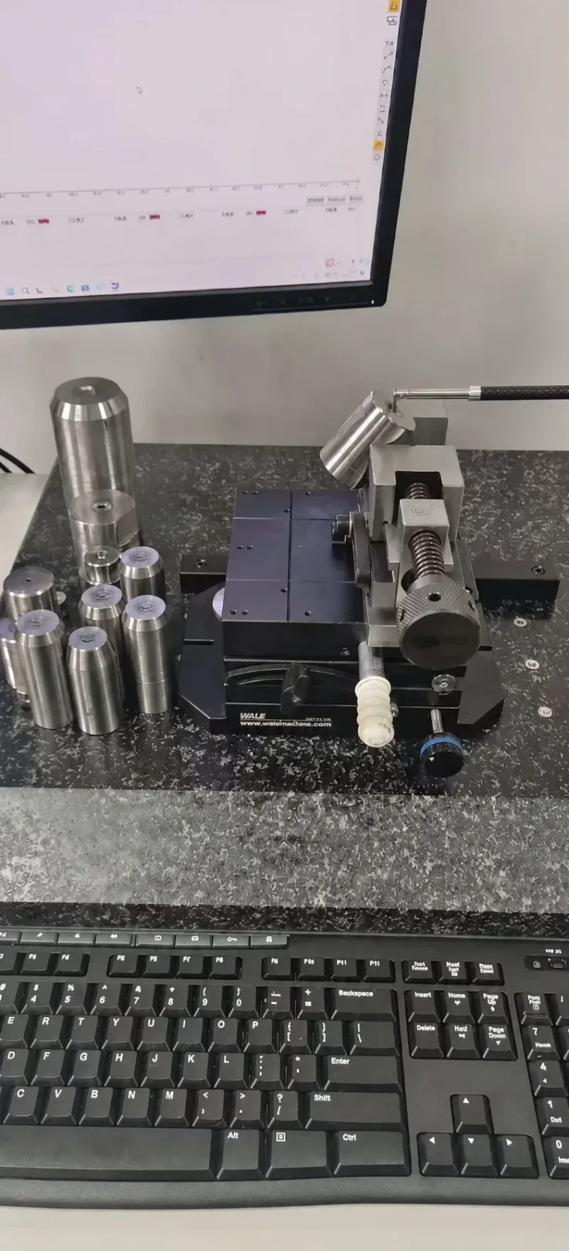
Dimensional checks run on a CMM at 20 °C against mold geometry of ±0.005 mm and cavity details at ±0.002 mm. Trials follow a T0 to T2 sequence with first-article approval before production release.
DieStrike couples validation to sampling. Mold trials run the T0 to T2 sequence with first-article approval before release, and the X-ray report travels with the dimensional report on busbar programs. Connector OEMs including TE Connectivity, Amphenol and Luxshare run this same evidence chain on HV interconnect work.
FAQ: EV Busbar Overmold Molds
Q1. What mold steel should I use for a glass-filled V-0 busbar overmold?
Harden cavity steel to at least HRC 58, and to HRC 62 where anchors and shut-off lands concentrate wear. Glass at 30 to 40% erodes unhardened cavities within roughly 100,000 shots. Put the hardness and steel grade in the RFQ so the mold price reflects them.
Q2. How do I stop the copper insert from shifting during injection?
Locate on stamped datum holes with pilot pins at 0.02 to 0.05 mm fit. Clamp the insert flat on the nest seat and gate symmetrically so fill pressure balances. Verify with X-ray on first articles, and hold the shift target under 0.3 mm to keep creepage valid.
Q3. Why does my busbar housing warp after molding?
Warp comes from asymmetric plastic, glass orientation and the heat-sink freeze at the copper face. Keep jacket sections symmetric and add ribs across the width at 50 to 60% of wall thickness. Run mold temperature on the hot side of the window, 70 to 80 °C for PBT.
Q4. Which compound fits an 800 V battery busbar?
PBT with 30% glass V-0 covers most distribution work at the lowest cost. PA66 glass V-0 adds toughness and continuous heat near 150 °C. PPS with 40% glass serves bays above 150 °C or where CTI demand is highest. Let the creepage and CTI class from the customer standard pick the grade.
Q5. Do busbar molds need X-ray inspection at every trial?
Run X-ray or CT on first articles and after any mold repair that touches nests or anchors. Insert position is invisible from outside the part, and a 0.3 mm drift can erase a designed creepage path. Sampling and dimensional checks alone will not catch it.
The Bottom Line
Busbar tooling stands on four decisions. Stamped anchors, a V-0 compound matched to the creepage class, clamping against cavity pressure, and warp control around a heat-sink core. DieStrike builds these insert molds as IATF 16949 certified tools at ±0.005 mm with HRC 62 cavities in 2 to 5 weeks.
Send us your busbar part drawing via our contact page for a 24 hour DFM review.
KEEP READING
Related Reading
How to Design Molds for Automotive Connectors
Low-voltage connector molds hold terminal pitch to ±0.01 mm across 16 to 64 cavities. Compare them with HV busbar tooling before you cut steel.
Read articleArticleHow to Design Insert Molds: Retention, Loading and Cycle
Insert nests hold 0.02 to 0.05 mm datum fits while copper conducts heat at roughly 390 W/m·K. Retention, loading and cycle rules for metal cores.
Read articleArticlePBT Injection Molding: Material Guide for Connectors
PBT with 30% glass shrinks 0.3 to 0.9% and vents at 0.01 to 0.03 mm. The resin data behind busbar and connector tooling decisions.
Read articleServiceMold Design & DFM
Get a DFM review of your busbar part within 24 hours. Anchors, creepage zones, gating and warp risk checked before any steel is cut.
Read articleNEXT STEP
Ready to Start Your Mold?
Send us your element dimensions or part numbers — our team responds within 24 hours with pricing and lead time.

Written by
Ray ChanMold Buyer's Guide Author · Precision Mold Manufacturing Specialist. Ray helps global importers, distributors and OEMs source factory-direct molds and mold parts.