
PPS Injection Molding: Material Guide for EV and Thermal Parts
Table of Contents
On shot 9,300 of a 48-cavity battery connector program, a PPS mold sat at 112 °C against a 150 °C target. Flash crossed one parting line at 0.10 mm, 600 housings went to quarantine, and the toolmaker spent a shift grinding shutoff surfaces.
PPS, polyphenylene sulfide, is the semi-crystalline workhorse behind EV connectors and thermal parts. Its benzene-sulfur backbone shrugs off 200 °C continuous heat, coolant splash, and flame where PBT softens. Molding grades are reinforced, and 40% glass fiber, GF40, dominates the tooling floor.
This guide is written for mold buyers and tooling engineers who quote and build PPS tools. It maps the properties that set mold rules, the design decisions, the processing window, and the defects that trace back to the tool. Values are typical published ranges for glass-reinforced compounds, mostly GF40. Verify every number against the specific grade datasheet before steel is cut.
The Snapshot
- GF40 PPS melts at 280-285 °C, so barrel zones run 300-340 °C and the mold must hold 130-180 °C for full crystallinity.
- Shrinkage is anisotropic: GF40 grades run 0.2-0.5% in the flow direction and up to 1.0% across flow.
- HDT clears 260 °C at 1.82 MPa, continuous service sits near 200-220 °C, and UL94 V-0 holds at thin walls.
- Flexural modulus reaches 14-19 GPa, and 24-hour water absorption stays below 0.05% on GF grades.
- Vent depth belongs at 0.01-0.02 mm, because hot cavities flash easily and outgassing above 350 °C leaves H2S traces.
What Is PPS and Why It Molds Differently
PPS belongs to the polyarylene sulfide family, commercialized in the 1970s and sold under brands such as Ryton, Fortron, Tedur, and DIC. The molecules alternate benzene rings and sulfur atoms, a structure that resists oxidation, solvents, and heat. Melt behavior follows crystallinity, so the tooling rules hinge on crystal growth, not on price.
Most molding grades are compounds with 30 to 50% glass fiber, mineral filler, or a blend. GF40 is the most common spec in connector and thermal programs. The filler raises stiffness, cuts shrinkage, and makes the melt abrasive. Published melting points cluster near 280-285 °C for reinforced linear grades.

The mold sees PPS differently than the part does. A crystalline skin forms only when the cavity holds roughly 130 °C or hotter. Run the tool colder and the surface freezes amorphous, losing crystallinity, heat resistance, and flatness at once.
Two resin families, linear and cross-linked, sit behind the brand names. Linear grades recover toughness after molding, which helps weld-line duty. Cross-linked grades flow into long, thin walls and resist creep at temperature. GF40 compounds run about 1.5 to 1.65 g/cm³, a number buyers use when quoting shot weight.
Four traits set every rule that follows. The mold must run hot for crystallinity. Shrinkage is anisotropic, glass erodes tool steel, and overheated melt outgasses. Each trait maps to a design decision covered below.
Properties That Drive Mold Design
Material selection and tool design are one decision, not two. The table below maps the PPS properties that matter most to the mold choices they force. If a datasheet number is missing at RFQ time, this list tells you what to ask for.
| PPS Property | Typical Value | What It Drives in the Mold |
|---|---|---|
| Melting point | 280-285 °C, linear GF grades | Barrel and runner zones sized for a 300-340 °C melt |
| Mold temperature need | 130-180 °C by wall and flatness spec | Heated mold architecture, oil or electric, insulated cooling |
| Mold shrinkage | Flow 0.2-0.5%, cross-flow up to 1.0% on GF40 | Zone-by-zone cavity compensation. Gate position sets the flow axis |
| HDT at 1.82 MPa | 260 °C and above on GF grades | Thin sections near powertrain heat sources |
| Continuous service | 200-220 °C typical | Steel choice and venting for long, hot production runs |
| Flexural modulus | 14-19 GPa on GF40 | Thin stiff ribs. Ejection loads concentrate on pins |
| Water absorption | Below 0.05% in 24 hours | Stable wet dimensions. Drying is short insurance |
| Flammability | UL94 V-0 at thin walls on many grades | No flame-retardant additives that outgas in the mold |
| Filler abrasiveness | 30-50% glass or mineral | Hardened cavities, coated gates, slides, and cores |
← swipe to scroll →
Table: typical published ranges for glass-reinforced PPS injection-molding grades, mostly GF40. Verify against the specific grade datasheet.
Shrinkage and crystallinity. Shrinkage is the most misread number on a PPS datasheet. GF40 grades run 0.2 to 0.5% in flow and up to 1.0% across flow, so one number never fits a cavity. A 130-180 °C mold grows a crystalline skin that shrinks predictably, while a cold mold freezes an amorphous surface with drifting dimensions. Compensate per zone and per gate, following our five shrinkage compensation rules.
Heat resistance. HDT clears 260 °C at 1.82 MPa on glass-reinforced grades. Continuous service ratings reach 200-220 °C, with short peaks higher depending on grade. The mold must deliver flat parts that hold pin pitch and sealing faces through that duty. A part that leaves the tool warped stays warped at 200 °C.
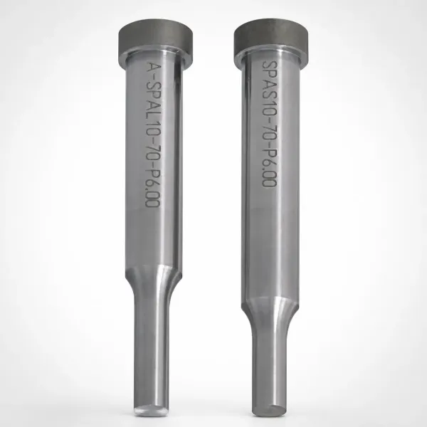
Stiffness and creep. Flexural modulus runs 14-19 GPa on GF40, roughly triple an unreinforced resin. Ribs stay stiff at temperature, which is why pump impellers and housings keep their shape under load. The trade shows up at ejection, since a stiff, low-ductility part cracks instead of flexing off a core.
Chemical resistance. PPS has no known solvent below about 200 °C. Coolant, transmission fluid, brake fluid, and EGR condensate leave it alone. That resistance, not price, is why OEMs specify PPS in wet, hot bays.
Flame and electrical. Many grades hold UL94 V-0 without halogen additives, at wall thicknesses down to roughly 0.8 mm on typical datasheets. Arc resistance and tracking resistance suit high-voltage EV components. Molders gain from that chemistry, since no additive outgassing plates vents or fogs cavities.
Moisture and expansion. Twenty-four-hour water absorption sits below 0.05%, so dimensions hold in humid assembly plants. Thermal expansion still couples with steel, and molded-over inserts see the CTE mismatch at every heat cycle. Shrinkage compensation must account for insert placement before machining starts.
Mold Design Considerations
Hot mold architecture. A 130-180 °C cavity is too hot for standard water circuits. Oil-tempered units deliver heat to 180-200 °C, and electric cartridge heaters work where oil is not wanted. Cooling must be designed as an insulated circuit, often with the same channels switched between heating and cooling. Insulate the mold from the machine platens so edges hold temperature, and keep zone-to-zone spread near 5-10 °C.
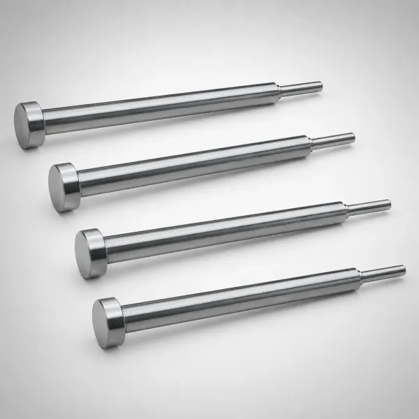
Thermal expansion of the tool. Tool steel grows about 11-13 µm per meter per kelvin. A 300 mm wide mold base gains roughly 0.5 mm between 20 °C and 160 °C. Slides, ejector clearances, and guide fits set at room temperature must still work hot. Measure fits at operating temperature during the first trial, not only at assembly.
Steel and wear protection. GF40 melt scrubs steel at the gate, along ribs, and through shutoffs. P20-class tooling erodes on long runs, so production tools start in hardened steel. H13-class at HRC 48-52 covers cores and slides, and S136-class stainless suits corrosive vent gases and humid lines. Coat gates, slides, and ejector tips with TiN, TiAlN, or CrN where glass passes.
Gate design and gate wear. Edge, tab, and fan gates direct flow and fill thin walls fast. Glass erodes the gate land, widening it over time, which changes packing and invites flash. Fit replaceable gate inserts in coated hardened steel and track land width at preventive maintenance. An undersized gate freezes early and starves the cavity during hold.
Venting and outgassing. Vent depth belongs at 0.01 to 0.02 mm on PPS cavities. Deeper vents flash at hot mold temperatures, because the thin melt enters any gap. Blocked vents cause burn marks at end of fill, and degraded melt above 350 °C adds gas load, releasing trace H2S. Full layout rules sit in our guide to mold venting.
Weld lines. Glass fibers do not cross a knit line, so weld strength can fall to 40-60% of base values. Position gates so critical faces fill from one direction, and keep the mold hot to improve knit strength. Overflow wells at suspect locations give trapped flow somewhere to go. Connector-tooling detail follows our automotive connector mold guide.
Sprue and gate freeze. PPS sets fast once flow stops, so a cold sprue freezes early and cuts off packing. Size the sprue and gate so the cavity packs before freeze-off, and keep the sprue bushing cool enough to release. On hot molds, balance that sprue cooling against cavity heating so one circuit does not fight the other. Multi-cavity balance methods apply directly to PPS tools.
Processing Window
Drying. PPS absorbs little water, below 0.05% in 24 hours for GF grades. Standard practice still dries at 120-150 °C for 3 to 5 hours, targeting under 0.02% moisture at the hopper. A dehumidifying dryer with a -40 °C dew point is typical. Skipping drying rarely shows splay, but removes one variable from a narrow process.
Melt temperature. Run GF40 grades with barrel zones between 300 and 340 °C. The melting point sits at 280-285 °C, so the melt needs margin, but sustained barrel heat above 350 °C starts degradation. Residence time above that zone must stay short, under roughly 10 minutes. Shot size at 30-70% of barrel capacity keeps the melt moving.
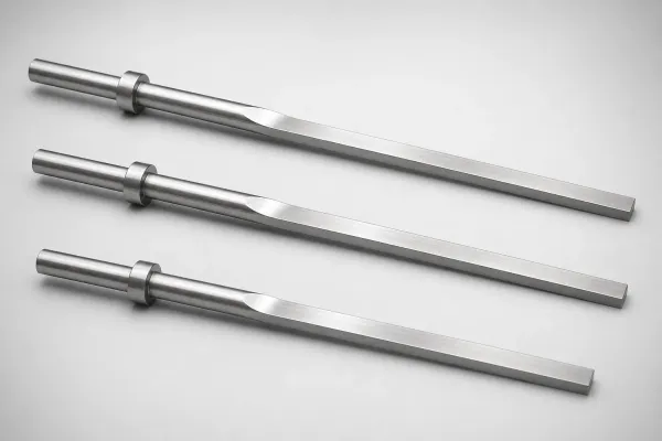
Screw and nozzle. Glass makes the melt abrasive to the screw too. Use a hardened screw, check ring, and barrel lining rated for glass-filled resins, and inspect the check ring for wear at maintenance. A positive shutoff nozzle prevents drool between shots on long cycles.
Mold temperature. Set cavity temperature at 130-180 °C, matched to wall thickness and the flatness spec. Thin walls run toward 130-150 °C for cycle speed, and thick sections with weld lines run 150-180 °C for knit strength and crystallinity. Hold the set point within about 5 °C zone to zone. Oil heating holds that band better than edge-mounted cartridge heaters on large plates.
Speed, pressure, and cycle. Fill thin walls fast, but not so fast that trapped air compresses into burns. Injection pressure typically reaches 80-140 MPa, and hold pressure runs high enough to pack an anisotropic shrinkage profile, often 60-100 MPa. Cycle time runs longer than cold-mold resins because the tool must cool the part from 130-180 °C before ejection. Connector and impeller tools commonly cycle in 20-40 seconds.
Trial and measurement. Measure first articles after conditioning at 23 °C and 50% relative humidity for at least 24 hours. PPS crystallinity keeps developing briefly after ejection, so early shots can read small. Compare trial shots on the same conditioning clock, and record gate freeze time at the trial. Shrinkage tuning then follows the per-zone method instead of guesswork.
Annealing and post-mold behavior. Some programs anneal PPS parts to stabilize crystallinity. Typical anneal runs 200-230 °C for 2 to 4 hours where the datasheet allows. The mold still does the heavy lifting, since uniform cooling limits the stress annealing must erase. Confirm the grade datasheet before scheduling any oven step.
Common PPS Applications: EV Connectors and Thermal Parts
EV battery connectors, HVIL interlock housings, and busbar holders lead PPS work on our EV energy tooling floor, where 150 °C bays are the baseline. Electric coolant pump impellers, thermostat bodies, and PTC heater manifolds hold 200-220 °C continuous ratings in the hottest coolant bays of modern EV packs. On the mold side, first-pass yield follows cavity temperature control, vent depth, and gate wear more than any single press setting. Connector design rules transfer directly from our automotive connector mold design guide, including core-and-cavity fit, terminal-hole pin placement, and ejector layout. Sixteen to 48 cavity tools carry the same discipline across automotive and injection mold manufacturing programs, with cooling and venting laid out as one system.
Defects: Mold-Side Root Causes
Most PPS rejects trace to a mold decision, not a bad shot. Each defect below maps to its mold-side root cause and the tooling fix.
Flash at the parting line. Flash is common because the thin melt runs at 130-180 °C mold temperatures, where steel fits open up. Root causes are vents deeper than 0.02 mm, worn shutoff lands, or low clamp tonnage. Fix with 0.01-0.02 mm vents, fitted hardened shutoffs, and enough tonnage for 80-140 MPa of injection pressure. Check shutoff fit at operating temperature, since thermal growth changes clearances.
Burn marks and black specks. Dark marks at the end of fill mean trapped air compressed the melt, or the melt itself degraded. PPS outgases above roughly 350 °C, releasing trace H2S that can etch cavity steel and leave black residue. Root causes sit in blocked vents, hot spots on the runner, and long residence. Open the vent plan, cut local vents at each air trap, and verify barrel temperature against the datasheet ceiling.
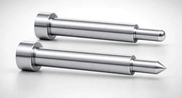
Weld lines and weak knit zones. Glass fibers pack along each flow front but do not cross the knit, so weld strength can drop to 40-60% of base values. Mold-side fixes start with gate placement so critical faces fill one way. A hot 150-180 °C cavity improves knit strength, and overflow wells give suspect lines somewhere to go.
Warpage and flatness drift. Anisotropic shrinkage curls thin housings when filling is unbalanced or the mold runs cold. A cavity below 130 °C freezes amorphous skin with different shrink, and flatness drifts shot to shot. Hold mold temperature in the 130-180 °C band, keep zone spread near 5 °C, and compensate cross-flow shrinkage on the drawing. Parts that still warp usually point at wall-thickness differences in the part design.
Gate and cavity wear. GF40 erodes gates, slides, and pin tips over long runs, widening the gate and changing packing. Coated gate inserts with TiN or TiAlN outlast uncoated steel by several times at the same hardness. Track gate land width at preventive maintenance and swap inserts on schedule before dimensions drift.
Short shots and poor packing. Thin ribs trap air, and early gate or sprue freeze starves the cavity during hold. Check vent depth along ribs, gate cross-section, and sprue size before blaming the machine. On hot molds the sprue bushing cools faster than the cavity, so a cold slug zone can freeze the feed. Balance sprue cooling against cavity heating as one circuit.
Ejection cracks and sticking. PPS parts eject hot and stiff, so they crack where ejection area is small. Plan draft of 0.5 to 1.5 degrees on ribs and bosses, and use sleeves around terminal holes. Polish and coat core faces so the part releases at 130-180 °C without drag. Ejector pins should land under ribs, not in open walls.
PPS vs LCP vs PBT for Harsh Environments
PPS, LCP, and PBT cover most connector and thermal programs, and the choice turns on sustained heat, thin-wall precision, and cost. The table below compares typical published values for 30-40% glass-reinforced grades of each.
| Property | PPS (GF40) | LCP (30-40% Glass) | PBT (30% Glass) |
|---|---|---|---|
| Melting point | 280-285 °C | About 335 °C | About 225 °C |
| Continuous service | 200-220 °C | 200-240 °C | 120-140 °C |
| HDT at 1.82 MPa | 260 °C and above | 240-310 °C | 200-215 °C |
| Shrinkage, flow | 0.2-0.5% | 0.1-0.3% | 0.3-0.6% |
| Shrinkage, cross-flow | Up to 1.0% | 0.4-0.8% | 0.6-1.0% |
| Water absorption, 24 h | Below 0.05% | Below 0.05% | 0.05-0.10% |
| Brief 260 °C reflow | Marginal, melts near 280 °C | Yes | No |
| Relative material cost | Mid-high | Highest | Lowest |
← swipe to scroll →
Table: typical published ranges for glass-reinforced injection-molding grades. Verify each value against the specific grade datasheet.
Where PPS wins. PPS owns sustained 200-220 °C service plus chemical attack, the combination inside EV coolant loops and powertrain bays. PBT softens past 140 °C, while PPS holds stiffness and dimensions wet or dry. For walls above 0.5 mm in hot fluid contact, PPS is the default.
Where LCP still wins. LCP fills 0.15 mm walls and holds pin pitch through 260 °C reflow, with shrinkage as low as 0.1% in flow. Where thin-wall precision beats sustained heat, LCP carries the part. Its cost and flash sensitivity make it the wrong pick for thick coolant housings. See the full comparison in our LCP material guide.
Where PBT still wins. PBT costs least and molds easily on cool tools. Its 120-140 °C continuous ceiling rules it out of engine bays and hot coolant lines. For interior and low-heat terminal housings, PBT keeps the economics. Details sit in our PBT material guide.
The selection rule. Choose PPS when the part sees 150-220 °C service, hot coolant, or aggressive fluids. Choose LCP when walls fall below 0.3 mm or reflow heat dominates. Choose PBT when peak heat stays under 140 °C and cost rules.
The mold consequence. Each resin reshapes the tool. PBT tools run cool with standard vents, and LCP tools need 0.005-0.015 mm vents with hardened cavities. PPS tools sit between, with hot 130-180 °C cavities, 0.01-0.02 mm vents, and hardened coated steel. Tooling differences are real, but scrap on a 200 °C duty part costs more than the steel ever will.
FAQ: PPS Injection Molding
Q1. What mold temperature does PPS really need?
Run cavities at 130-180 °C, matched to wall thickness and the flatness spec. Thin walls run toward 130-150 °C, and weld-critical thick sections run 150-180 °C. Below 130 °C, surface crystallinity drops and flatness drifts. Oil temperature control holds the band better than water, which needs pressure to stay liquid above 120 °C at shop conditions. For housings over 2 mm wall, treat 160-180 °C as the floor.
Q2. What vent depth should a PPS mold use?
Cut vents 0.01 to 0.02 mm deep, with lands kept short before the relief channel. Deeper vents flash because the melt is thin and the mold runs hot. Blocked vents cause burns at the end of fill. Verify vent condition at operating temperature, since steel growth changes the effective gap.
Q3. What shrinkage values should I use when cutting PPS cavities?
Never one number. GF40 grades run 0.2-0.5% in flow and up to 1.0% across flow, so compensate per zone and per gate layout. Mold temperature and crystallinity shift the real value, so hold the cavity at 130-180 °C before you tune. Confirm the grade anisotropy on the datasheet before cutting steel. Using one chart number across a 100 mm width can misplace a datum by 0.2-0.5 mm.
Q4. PPS or LCP for my EV connector?
Choose LCP when walls drop below 0.3 mm or the part must pass 260 °C reflow with precision. Choose PPS when the part carries sustained 150-220 °C heat or sits in coolant, where LCP flash sensitivity and cost buy nothing. PBT handles only interior heat below 140 °C. Compare datasheets at the actual service temperature, not at room temperature. Verify with a heat-age test at 180-200 °C before the tool is quoted.
Q5. Why do my PPS parts show black specks near the gate and vents?
Black specks usually mean the melt degraded above roughly 350 °C, releasing trace H2S and char that plates the cavity. Check barrel temperature, residence time, and hot spots on the runner. A shot size below 30% of barrel capacity lets melt sit too long. Shorten residence, cool hot zones, and clean the barrel at material changes.
The Bottom Line
PPS is a hot-mold resin whose habits people misjudge until a trial. Run the cavity at 130-180 °C, cut vents at 0.01-0.02 mm, harden and coat the steel, and compensate shrinkage per zone. Do that, and GF40 tools hold flatness and dimensions across 200-220 °C service and millions of shots.
The resin will not rescue a tool that flashes, burns, or warps, and the press will not fix a cavity cut for the wrong shrinkage. Most PPS problems found at trial were visible on the drawing weeks earlier. That is what a mold-design review catches before steel is ordered, at a cost far below a change order.
DieStrike builds production PPS molds under IATF 16949 on a 120+ machine floor. Standard tolerance sits at ±0.005 mm, precision features at ±0.002 mm, and cavity steel hardens to HRC 62. Production molds ship in 2 to 5 weeks, with standard components in 3 to 7 days. Connector programs for TE Connectivity, Amphenol, and Luxshare follow the same hot-mold discipline.
KEEP READING
Related Reading
LCP Injection Molding: High-Temperature Material Guide
LCP melt fills 0.15 mm walls and shrinks 0.1-0.3% in flow. Compare thin-wall precision before you cut steel.
Read articleMATERIAL GUIDESPBT Injection Molding: Material Guide for Connectors
PBT caps near 120-140 °C continuous service. If your part sees 150-220 °C bays, PPS outlasts it.
Read articleDESIGN GUIDEHow to Design Molds for Automotive Connectors
Connector tools need fine vents and hardened cavities. Core-and-cavity rules that transfer to PPS programs.
Read articleDESIGN GUIDE5 Shrinkage Compensation Rules for Mold Design
PPS shrinks 0.2-0.5% with flow and up to 1.0% across it. Five rules that stop cavity compensation errors.
Read articleNEXT STEP
Ready to Start Your Mold?
Send us your element dimensions or part numbers — our team responds within 24 hours with pricing and lead time.

Written by
Ray ChanMold Buyer's Guide Author · Precision Mold Manufacturing Specialist. Ray helps global importers, distributors and OEMs source factory-direct molds and mold parts.