
How to Design Molds for Long-Fiber Reinforced Plastics
Table of Contents
A 30 percent long-glass polypropylene underbody shield lost 46 percent of its weld-line tensile strength on the first trial. The comparison was against the flow-direction value on the same part. The tool had been cut with a 1.2 mm gate on a 3 mm wall. That gate sheared 12 mm pultruded pellets down to bundles under 2 mm, and no barrel temperature or injection profile put the length back. The part passed every dimensional check, failed the structural requirement, and the correction cost a new gate insert plus nine days of schedule.
This guide covers the tooling decisions that set fiber length, wear life and warpage in long-fiber molding. It runs through runner and gate sizing, abrasion protection, vent depth, wall and rib rules, shrinkage direction, ejection, the machine side and trial acceptance.
The Snapshot
- 10 to 25 mm pellets in, 5 to 15 mm fibers in the part. A 1 to 1.5 mm gate breaks the bundles below 3 mm and pushes weld-line loss from 30 to 50 percent up to 50 to 70 percent.
- Full-round runners of 12 to 20 mm, gate depth 3 to 6 mm. On a 3 to 4 mm wall the gate belongs at 1 to 1.5 times the wall thickness, not the 0.8 to 1.2 mm land that suits a short-glass job.
- Gates wear 2 to 4 times faster than under short glass fiber. 1.2344 at HRC 50 to 54 with a carbide or DLC insert at the gate and the vents is the working combination.
- Vents 0.03 to 0.05 mm deep on a 2 to 4 mm land. A 0.020 mm vent is bridged by a single 12 mm fiber, so the gas path closes and the last-fill corner burns.
- 30 to 40 percent LFT in PP shrinks 0.2 to 0.6 percent along flow and 0.8 to 1.2 percent across it. Orientation, not packing pressure, drives the warpage that rejects the part.
- 2 to 4 percent of throughput is the screw and barrel wear budget. A bimetal barrel and a wear-resistant screw are process equipment on this family, not upgrades.
What Changes With Long-Fiber Reinforcement
Short-glass compounds carry fibers of 0.2 to 0.6 mm and they reach the press that way. The screw, runner and gate cut a further 20 to 40 percent. The part keeps the data sheet modulus with a weld line at 30 to 50 percent of the flow-direction strength.
Long-fiber thermoplastic pellets arrive as pultruded bundles of 10 to 25 mm. A standard LFT-PP grade runs 10 to 12 mm. The direct LFT-D route feeds 20 to 25 mm bundles from a twin-screw extruder straight into the tool. The screw conveys those bundles without dispersing them.
Build the flow path for fiber survival and the part lands at 5 to 15 mm. Weld-line retention then improves to 50 to 70 percent of the flow-direction value. Build the same tool for a short-glass job and the same resin lands under 3 mm at the weld line. That costs 50 to 70 percent of the strength at the joint.
Every restriction between the nozzle and the cavity removes length. A sharp runner corner, a small gate, a narrow drop bore and a long thin flow path all shear bundles. Barrel temperature and injection speed preserve fiber that is still intact, and they cannot restore length that a gate has already cut.

Three consequences follow for the drawing set. Fiber length loss is a flow-path problem, so runner and gate sizing moves to the front of the design. Abrasion at gates and vents runs 2 to 4 times the short-glass rate at the same 30 to 40 percent load. Flow orientation drives shrinkage in two very different directions, which makes gate position the strongest control on warpage.
The family covers LFT-PP, LFT-PA6 and LFT-PA66 plus in-line compounded grades. Parts run from underbody shields to automotive front-end modules, seat structures and battery frames. The glass-filled resins guide covers short and mineral-filled compounds, and its wear arithmetic still applies here at a higher rate.
Melt Delivery: Runners, Gates and Drops
Runner design sets the fiber length that arrives at the gate. Use a full-round runner of 12 to 20 mm for most parts, and size it from the thickest wall rather than from the part weight. A 3 to 4 mm wall takes a 14 to 16 mm runner, while a 5 mm structural section takes 18 to 20 mm.
Keep the runner cross-section constant from the sprue to the last drop. Every step down in diameter is a shear point, and a step from 16 mm to 10 mm costs roughly 2 mm of fiber length. Radius every direction change at 1.5 times the runner diameter, and keep the total runner under 300 mm on a single-drop part.
Gate depth runs 3 to 6 mm on a 3 to 4 mm wall, which is 1 to 1.5 times the wall thickness. A 1 to 1.5 mm gate shears the bundles below 3 mm. It takes weld-line loss from 30 to 50 percent up to 50 to 70 percent. That gate is the most expensive line on the drawing when it is drawn wrong.
Gate land length stays short at 1 to 2 mm. A long land at a small depth behaves like a shear die. It converts a 12 mm bundle into a dispersed short-fiber melt before the cavity sees it. A generous gate with a short land fills the part at lower pressure and passes fiber intact.

Avoid hot runner valve pins and narrow drops on this family. A 4 to 6 mm drop bore with a valve pin creates two shear gaps, and the pin seat cuts bundles on every shot. Where the cycle demands a hot system, use a full-bore drop of 8 to 12 mm and delete the pin. The alternative is a 20 to 35 percent loss in weld-line strength. Systems for higher melt temperatures are covered in the high-temperature resins guide, and the shear arithmetic is the same.
The LFT-D route changes the layout. A twin-screw extruder compounds the melt and feeds the tool directly, so the runner is often a short sprue of 40 to 80 mm. That short path is why direct compounding holds 15 to 20 mm fibers where a conventional runner holds 8 to 12 mm.
| Stage in the flow path | Typical fiber length | Design control | Failure if the control is missed |
|---|---|---|---|
| Pellet as supplied | 10 to 25 mm | Grade choice and LFT-D feed path | Below 10 mm the compound behaves as a short-glass grade and the structural claim is gone |
| Screw and check valve | 8 to 18 mm | Low-compression screw at 2:1 to 2.5:1 | A 3.5:1 compression screw removes 3 to 6 mm before the nozzle |
| Full-round runner | 6 to 15 mm | 12 to 20 mm diameter with 1.5D radii | A sharp corner on an 8 mm runner costs 3 to 5 mm of length |
| Gate | 3 to 8 mm | 3 to 6 mm depth, 1 to 2 mm land | A 1.2 mm gate lands the fiber below 3 mm and doubles weld-line loss |
| Part, flow direction | 5 to 15 mm | Balanced fill and gate placement | Long thin flows shear to under 4 mm at the last-fill end |
← swipe to scroll →
Table note: length bands are typical values for 30 to 40 percent glass LFT-PP and LFT-PA measured by pyrolysis and image analysis. Confirm against the resin supplier data sheet and the ash content test on the first trial shot.
Place the gate so the longest flow ends at a trimmed edge rather than at a structural rib. Weld lines form where two flow fronts meet. A weld line inside a load path is a designed failure at 30 to 50 percent of the parent strength. Move the gate, add a drop, or thicken the section behind the weld so the knit has material to work with.
Abrasion: Wear Rates, Steels and Inserts
Long glass abrades a gate 2 to 4 times faster than short glass at the same 30 to 40 percent load. The bundle arrives as a stiff rod that scrapes the gate land. Damage concentrates on a 1 to 2 mm land at high velocity. A gate that measures 4.00 mm at the trial can reach 4.60 mm inside 100,000 shots.
That growth is not cosmetic. A gate that opens by 0.5 mm changes the fill pattern, moves the weld line and drops cavity pressure by 5 to 10 percent. Parts then run light at the far end, and the process window narrows until the gate is re-cut.
Steel choice follows the wear map. 1.2344 (H13) at HRC 50 to 54 is the standard cavity steel for long-fiber tools, and it holds a gate for 200,000 to 400,000 shots. Nitriding to a 0.15 to 0.30 mm case adds 2 to 3 times the life at the gate and vent edges.
Put the highest-wear areas into replaceable hardware. A cemented carbide block at HRC 88 to 92 can be swapped in a few hours. The same applies to a powder metallurgy block at HRC 60 to 64. Neither option requires re-cutting the cavity insert.
Design the block with a dowel location and a 0.02 mm fit so the replacement repeats. Standard hardened inserts from the custom mold insert range are finished to 0.002 mm on EDM and jig grinding. That is the tolerance a gate block needs to drop back into the same pocket.

Coatings buy the interval between changes. DLC at 1 to 3 micrometre on a gate land holds the dimension and lowers friction. PVD CrN or TiAlN at 2 to 5 micrometre protects vent lands and cores. Plan a re-coat at 300,000 to 500,000 shots and record the gate dimension at every 50,000 shot service.
Vents wear for the same reason. A 0.04 mm vent land under an abrasive melt opens toward 0.08 mm, and at that depth the tool flashes along the whole perimeter. Measure vent depth with a feeler gauge or an optical gauge at every service. Build the vent as a replaceable insert on any tool above 500,000 shots.
| Surface | Specification | Where it belongs | Notes and limits |
|---|---|---|---|
| 1.2344 (H13) | HRC 50 to 54, nitrided 0.15 to 0.30 mm | Cavity inserts on general long-fiber work | 200,000 to 400,000 shots at a gate before re-cut |
| 1.2379 (D2 type) | HRC 58 to 62 | Small gate blocks and vent inserts | Higher wear resistance, lower toughness at a thin land |
| Cemented carbide | HRC 88 to 92 equivalent | Gate blocks on tools above 500,000 shots | Replaceable, 3 to 5 times the life of H13, needs a supported seat |
| Powder metallurgy steel | HRC 60 to 64 | Gate and vent blocks on high-volume programs | 2 to 3 times the wear life of 1.2344 at higher material cost |
| DLC coating | 1 to 3 micrometre | Gate land, drop tip, ejector sleeves | Re-coat at 300,000 to 500,000 shots, needs a clean process |
| PVD CrN or TiAlN | 2 to 5 micrometre | Vent lands, cores, slides | Keeps a 0.03 to 0.05 mm vent edge stable |
← swipe to scroll →
Table note: hardness and coating figures are typical industry ranges for abrasive glass-filled tooling. Confirm the heat treatment certificate, the nitriding case depth and the coating thickness report before the tool is assembled.
Venting: Depth, Land and Perimeter Layout
Long fibers change what a vent can be. A single 12 mm fiber is wider than a 0.020 mm gap, so a conventional shallow vent is bridged and closed. Depth runs 0.03 to 0.05 mm on a 2 to 4 mm land. Behind the land sits a 0.3 to 0.5 mm relief channel to atmosphere.
That is 2 to 3 times the depth used on an unfilled resin, and it is safe here for a measurable reason. A long-fiber melt runs 30,000 to 100,000 Pa·s at the gate. That is 2 to 4 times a short-glass compound and 10 to 50 times an unfilled one. A melt that thick does not flash through a 0.04 mm gap under 40 to 80 MPa of cavity pressure.
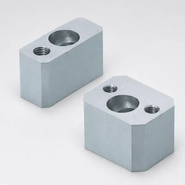
Cut vents around the full perimeter rather than at four points. Long-fiber parts are thick-walled at 2.5 to 4 mm and they fill slowly, so gas has time to reach any edge. A full-perimeter vent on a 0.03 mm land removes the trapped-air burn. That burn appears in the last-fill corner of an underbody shield or a battery frame.
Clean vents on a shot count. A glass-filled melt leaves a film that narrows the land by 0.01 to 0.02 mm inside 5,000 to 10,000 shots. The burn marks then return with no change to the process. Put vent inspection into the same service pass as the gate measurement, and record both numbers in the tool file.
Add vacuum assist on parts above 1.5 kg or where the flow path exceeds 800 mm. Pulling the tool to 100 to 300 mbar before the shot removes the gas before the melt arrives. It also lets the vent depth sit at the low end of 0.03 mm.
Wall Thickness, Ribs and Draft
Long-fiber parts run thicker walls than a short-glass counterpart. The working band is 2.5 to 4 mm, and most structural parts land at 3 to 3.5 mm. Below 2.5 mm the flow-length-to-thickness ratio passes 150:1, and the bundles bridge at the flow front and break apart.
Ribs run at 60 to 70 percent of the nominal wall. A 3 mm wall takes a 1.8 to 2.1 mm rib with a 0.5 to 1 mm radius at the base. The flanks carry 1 to 1.5 degrees of draft. A rib at full wall thickness sinks the opposite surface and pulls fiber orientation into a visible read-through.
Draft runs 1.5 to 2.5 degrees, which is 1 to 2 degrees more than an unfilled part of the same geometry. Long fibers grip the steel, and a 1 degree wall that releases cleanly in unfilled polypropylene scuffs in LFT-PP. A textured surface needs 1.5 to 2 degrees added on top of the base angle.
Bosses follow the same rule. Keep the wall at 60 to 70 percent of nominal and add 0.5 to 1 mm of radius at the base. Support the boss with ribs instead of thickening the section. A boss at full wall thickness builds a 3 to 5 percent shrink void and a sink mark on the show surface.
Corner radii scale with the fiber. Use an inside radius of at least 1 mm, or 0.5 times the wall thickness, at every internal corner. A sharp corner concentrates stress and blocks fiber, which leaves a resin-rich zone that fails first under load.
Shrinkage, Orientation and Warpage
Long-fiber shrinkage is directional and large. A 30 to 40 percent LFT-PP shrinks 0.2 to 0.6 percent in the flow direction and 0.8 to 1.2 percent across it. That 2:1 to 4:1 ratio comes from fiber orientation, and it drives the warpage that rejects these parts.
The cavity compensates by direction. Cut a flat panel 0.4 percent large in the flow direction and 1.0 percent large across it, then mark the direction map on the drawing. One uniform allowance on a 1,200 mm panel bows the part by 3 to 6 mm.
Gate position sets the orientation map. A single end gate sends flow one way and gives predictable, strongly directional shrinkage. Multiple gates balance the flow and reduce warp, and every extra gate adds a weld line at 30 to 50 percent of the flow-direction strength.
Packing has limited authority over orientation. Cavity pressure at 40 to 80 MPa moves a short-glass melt and only partly offsets directional shrinkage here. The stronger levers are gate location, flow balance, wall uniformity and cooling symmetry, in that order.
Cooling balance matters more than cooling speed. A 5 °C difference between the two halves bends a 1,000 mm part by 0.5 to 1.5 mm. Run symmetric circuits in both halves, measure the cavity face at six points, and hold the pair within 3 °C.
Ejection and Part Removal
A long-fiber part is stiff, and it needs force rather than finesse. Ejection force on a 3 mm wall part runs 5 to 15 kN against 4 to 8 kN for the same geometry in unfilled polypropylene. A 6 mm ejector pin carries that load without marking, while a 3 mm pin on the same part can punch through the skin.
Size the pin count from the projected area. Use at least one pin per 2,000 square mm. Keep diameters at 4 to 8 mm on structural parts, and place pins on ribs, bosses and corners. A pin on a flat panel at a 3 mm wall deflects the part by 0.1 to 0.3 mm before it releases.

Draft and finish reduce the release force. A core polished to Ra 0.2 to 0.4 micrometre with 2 degrees of draft releases a 1.5 kg part easily. The same part on a 1 degree core at Ra 1.6 micrometre needs 40 to 60 percent more force.
Guide the ejector plate and support it. A long-fiber tool often carries 20 to 40 pins on a 1,500 mm plate, and that plate flexes 0.05 mm under load without support pillars. Preload the pillars 0.02 to 0.05 mm proud of the plate face and check the contact pattern with bluing.
Add air assist or a stripper where the geometry traps the part. A deep rib or a 0.5 mm step can hold a stiff part on the core, and pins alone will tear the corner. Air at 0.4 to 0.6 MPa for 0.5 to 1 second breaks the seal without touching the surface.
Machine Side: Screw, Barrel and Wear Budget
Long-fiber molding moves wear from the tool to the machine. A bimetal barrel with a 1 to 2 mm centrifugally cast lining and a wear-resistant screw are standard equipment for these compounds. A nitrided general-purpose screw loses 0.05 to 0.10 mm of flight diameter per 100 tonnes of LFT processed.
Budget 2 to 4 percent of throughput as screw and barrel wear cost. A cell running 300 tonnes of LFT-PP a year inspects the screw twice and expects a replacement inside 2 to 4 years. Put that number into the part cost model before the tool is quoted.
Screw geometry protects the fiber. Use a low-compression screw at 2:1 to 2.5:1 with an L/D of 20 to 25 and a generous feed section. A 3.5:1 compression screw disperses the bundles in the transition zone and removes 3 to 6 mm of length before the melt reaches the nozzle.
Watch the non-return valve. A worn check ring leaks 5 to 15 percent of the shot, and the leak path shears melt at high velocity. Inspect the ring every six months and replace it once the wear land passes 0.15 mm.
Keep the shot size in the 20 to 70 percent band of barrel capacity. Below 20 percent the residence time at 230 to 280 °C climbs past 8 minutes and the coupling agent degrades. Above 70 percent the melt has no time to homogenise and the fiber distribution varies from shot to shot.
Applications and Part Families
Long-fiber molding is a structural process, so the tool is built around the load path. Four families carry most of the work, and each one puts a different number first.
| Part family | Typical wall | Gate and runner note | Main reject mode |
|---|---|---|---|
| Underbody shield, 1.2 to 1.5 m | 2.5 to 3.5 mm | Edge gate 4 to 5 mm, single drop | Corner warp from 0.8 to 1.2 percent cross-flow shrinkage |
| Front-end module | 3 to 4 mm | 2 to 4 drops on a 16 mm full-round runner | Weld-line strength at 30 to 50 percent of the flow value |
| Seat structure | 3.5 to 4 mm | Direct sprue or a 6 mm hot drop | Rib read-through and fiber orientation drift |
| Battery frame | 3 to 4 mm | Sequential gates on an 18 to 20 mm runner | Flatness drift after 24 hours of relaxation |
← swipe to scroll →
Table note: wall and gate figures are typical starting points for 30 to 40 percent glass LFT compounds in automotive structural work. Confirm the grade, the flow length and the shrinkage data with the resin supplier before the cavity is cut.
Clamp force follows projected area and cavity pressure. A 1.2 m by 0.8 m underbody shield at 40 MPa of cavity pressure produces 38,400 kN of separating force, which is 3,840 tonnes. Parts at that size run on 4,000 to 5,000 tonne presses with 15 to 25 percent clamp margin.
Cavity count stays low. Above 90 percent of these parts run one or two cavities. Cavity plates reach 1,000 to 1,500 mm and tool mass lands between 4 and 12 tonnes. A left and right family layout in one tool is common. Stack and multi-cavity layouts are rare, because a 16 to 20 mm runner offsets the cycle gain.
Battery frames and seat structures add flatness requirements on top of the mechanical ones. A 1,200 mm frame is usually held to 0.5 to 1.0 mm of flatness after 24 hours of relaxation. That requirement drives the gate plan rather than the steel choice.
Inspection and Trial Acceptance
Fiber length is the acceptance variable on these tools, and it can be measured. Burn off the polymer in a muffle furnace at 625 °C and measure the ash residue by image analysis. The ash content should match the supplier certificate within 1 percent, and the number-average fiber length should land inside the 5 to 15 mm band.
Sample at three points: the runner or sprue, the gate outlet, and the finished part. Run the test on 3 to 5 shots at trial and again after 50,000 production shots. A gate that delivers 6 mm of fiber length at the trial and 4 mm at 50,000 shots is wearing. The gate dimension at the same service confirms that the wear is real.
Dimensional data covers both directions. Report flow-direction and cross-flow shrinkage separately over 30 to 50 shots, and hold the wall at ±0.10 mm on a 3 mm nominal. A single average shrinkage figure hides the orientation effect, and it will not predict the warp that appears on a panel.
Mechanical proof uses a weld-line test bar. Mold a two-gate tensile bar, test it to ISO 527, and compare the weld-line strength with the flow-direction value from the same shot. Acceptance at 50 to 70 percent of the flow-direction strength confirms that the runner and gate did their job. Anything under 40 percent means the gate is too small.
The tool specification should list gate depth and vent depth with a tolerance and an inspection interval. Write gate depth at 4.00 ±0.05 mm and vent depth at 0.04 ±0.01 mm, with a measurement at every 50,000 shot service. Those two numbers plus the fiber-length test define whether the tool still does what it was built to do. DieStrike builds long-fiber tooling to IATF 16949 with ±0.005 mm mold accuracy and ±0.002 mm on EDM and jig grinding. Injection mold manufacturing runs 2 to 5 week tool lead times, and standard components ship in 3 to 7 days.
Long-Fiber Mold Design FAQ
Q1. Why does a long-fiber gate need to be larger than a short-glass gate?
A 10 to 25 mm pultruded bundle is a stiff rod, and every narrow restriction cuts it. A 1 to 1.5 mm gate lands the fiber below 3 mm. Weld-line loss then moves from 30 to 50 percent up to 50 to 70 percent. A gate depth of 3 to 6 mm on a 3 to 4 mm wall passes the bundle without shearing it.
Q2. Can a hot runner be used on long-fiber reinforced plastics?
Only with care. A valve pin and a 4 to 6 mm drop bore add two shear gaps and cut the fiber on every shot. A full-bore drop of 8 to 12 mm with the pin deleted is the workable version. It still costs 20 to 35 percent of weld-line strength. On most programs a 60 to 80 mm sprue or a cold runner is the better trade.
Q3. How deep should the vents be on a long-fiber tool?
0.03 to 0.05 mm on a 2 to 4 mm land, with a 0.3 to 0.5 mm relief behind it. A 0.020 mm vent is bridged by a single 12 mm fiber and the gas path closes. The melt runs 30,000 to 100,000 Pa·s at the gate, so 0.04 mm does not flash under 40 to 80 MPa of cavity pressure.
Q4. Why do long-fiber parts warp when the wall is uniform?
Because shrinkage is directional. A 30 to 40 percent LFT-PP shrinks 0.2 to 0.6 percent along the flow and 0.8 to 1.2 percent across it. Fiber orientation sets that ratio, so gate position and flow balance control warp more than packing pressure does.
Q5. How long does a long-fiber mold last?
200,000 to 400,000 shots at the gate with 1.2344 at HRC 50 to 54. Cavity life reaches 500,000 to 1,000,000 shots with nitriding or a coating. Replaceable carbide gate blocks and vent inserts keep the tool in service. Those two features wear 2 to 4 times faster than they do under short glass.
The Bottom Line
Long-fiber tooling comes down to four numbers, and each one protects fiber length or flow orientation. First, a 12 to 20 mm full-round runner. Second, a 3 to 6 mm gate depth on a 3 to 4 mm wall. Third, a 0.03 to 0.05 mm vent on a 2 to 4 mm land. Fourth, a rib rule of 60 to 70 percent of the wall.
Everything else is wear management. Long glass abrades a gate 2 to 4 times faster than short glass. Gate and vent hardware therefore belongs in replaceable inserts from HRC 58 to 92, with a measured interval at every 50,000 shots. Hold the fiber at 5 to 15 mm in the part and the gate at its specified depth. The mechanical result is then designed in from the first drawing instead of recovered on the last trial.
KEEP READING
Related Reading
Custom Mold Inserts
Hardened gate, vent and wear inserts at HRC 58 to 62 with 0.002 mm EDM finishing.
Read articleServiceInjection Mold Manufacturing
IATF 16949 tooling with runners and gates sized to keep 10 to 25 mm fibers intact.
Read articleIndustryAutomotive Mold Making
Underbody, front-end and battery frame tools built for abrasive long-glass compounds.
Read articleArticleHow to Design Molds for Thick-Wall Parts
Cooling and shrinkage rules for the 2.5 to 4 mm sections that long-fiber parts use.
Read articleNEXT STEP
Ready to Start Your Mold?
Send us your element dimensions or part numbers — our team responds within 24 hours with pricing and lead time.

Written by
Ray ChanMold Buyer's Guide Author · Precision Mold Manufacturing Specialist. Ray helps global importers, distributors and OEMs source factory-direct molds and mold parts.