
How to Design Molds for Glass-Filled Resins: Wear, Gates and Steel
Table of Contents
A connector mold running GF30 PA66 at 1,200 shots per day can open its gate land by 0.05 mm within 150,000 cycles. That is enough to change fill time, shift the weld line and push critical pin dimensions out of a ±0.02 mm window. The tool still closes. The parts still look fine on the press floor. But the buyer's incoming inspection starts rejecting housings, and the root cause is a mold that was designed for unfilled resin and then switched to glass-filled material. Glass fibers are an abrasive slurry at injection pressure. Treating GF tooling like standard tooling is the single most expensive design mistake we see in automotive and connector programs.
Glass-filled grades are not going away. GF30 PA66 carries under-hood connectors, GF-PBT runs sensor housings and GF-PPS survives 200°C continuous service in EV powertrain parts. Every one of them eats soft steel, washes out gates and shrinks differently along the flow path than across it. This guide covers the mold-side response: wear mechanisms, gate and runner geometry, steel grades and coatings, cavity compensation, ejection, cooling and the cost math behind hardened tooling. Injection parameters appear only as inputs to tooling decisions, because that is where a mold maker actually controls the outcome.
The Snapshot
- Gate inserts for GF30-45% resins run at HRC 56-62 hardened steel or solid carbide, never pre-hardened P20 at HRC 28-32.
- Edge gate depth for glass-filled resins is typically 0.5-0.8x wall thickness, deeper than unfilled grades, to limit fiber-orientation freeze and pressure loss.
- Anisotropic shrinkage of GF resins differs 2-3x between flow and transverse directions, so cavity compensation must be direction-specific, not a single scale factor.
- Production targets for GF tooling run 500,000-1,000,000 shots, which rules out pre-hardened-only construction in wear zones.
- Hardened steels plus DLC or TD coating add a typical 10-25% mold cost premium and pay back well before 300,000 shots on high-volume GF programs.
How Glass Fibers Wear Out Molds
Glass fibers are harder than tool steel at the contact scale. Chopped E-glass fibers have a Mohs hardness around 6-7, while hardened H13 sits at roughly HRC 50-55. A single fiber cannot scratch a hardened surface easily. Millions of them, pressed against steel by melt at 600-1,400 bar and traveling 2-5 m/s through a gate, produce measurable erosion cycle after cycle. This is abrasive wear with a fatigue component, and it concentrates exactly where melt velocity peaks.
Three wear zones, three mechanisms. The gate land erodes first because velocity is highest there, often 10-30 m/s for a small gate on a GF30 shot. Runners wear next, mostly at direction changes where fibers impact the wall instead of sliding along it. Cavities and cores wear last but over the largest area, showing up as loss of polish, dull texture patches and slowly opening clearances on sliding components. The typical sequence on an unprotected P20 cavity insert is visible fiber polishing at 100,000 shots, measurable dimensional drift at 250,000 shots, and repair welding before 400,000.
Filler level scales the damage. Wear rate does not grow linearly with glass content. Industry testing on GF-PA66 shows the jump from 15% to 30% glass roughly doubles abrasive wear, and GF45 grades with mineral-glass blends can cut unprotected steel life to a third of the GF30 baseline. Fiber length matters too: long-glass grades keep fibers 0.5-1 mm intact after molding, while standard chopped fibers break to 0.1-0.3 mm in the gate. Longer surviving fibers sweep wider arcs and polish cavity surfaces faster.
Temperature makes it worse. GF-PPS and high-temperature GF-PA process at 280-320°C melt temperatures. Hot melt softens the steel surface microscopically and accelerates oxidation-assisted wear on any component above 200°C. This is why GF-PPS tooling that runs hot-cavity at 90-120°C surface temperature needs the same hardness attention as a hot-work die, not a general plastic mold.

Gate, Runner and Cavity Wear Numbers
Gate design for glass-filled resins is a compromise between erosion resistance, pressure loss and fiber breakage. Get the geometry right and the wear problem shrinks before steel selection even enters the picture. The rules below are typical industry figures for GF30 PA66, GF-PBT and GF-PPS at standard wall thicknesses of 1.0-3.0 mm.
Edge gate depth: 0.5-0.8x wall thickness. Unfilled resins often run edge gates at 0.4-0.6x wall. Glass-filled grades need the deeper band, 0.5-0.8x wall, because a shallow gate freezes fiber orientation at the entry, raises local shear and accelerates erosion at the land exit. For a 2.0 mm wall connector housing, that means a gate depth of 1.0-1.6 mm. Land length stays short, typically 0.5-1.0 mm, so the high-velocity zone is confined to a replaceable insert rather than spread into the cavity.
Gate land in hardened material only. The gate land should sit in an insert of HRC 56-62 through-hardened steel, or solid carbide for programs above 500,000 shots or GF45+ loads. Carbide gate inserts are standard practice in connector tooling for TE Connectivity, Amphenol and Luxshare style high-cavity programs, where 64 or 128 cavities each carry their own eroding land. A carbide land holds ±0.005 mm gate size roughly 5-10x longer than hardened steel under identical cycling.
Fan and film gates spread the erosion. Where the part geometry allows, a fan gate dilutes the same melt flow across a wider opening, cutting local velocity by 50% or more versus an equivalent rectangular edge gate. That directly extends land life. The trade-off is a longer trim witness and a bigger shut-off face, so fan gates earn their keep on flat housings and brackets rather than on small connector bodies.
Runner sizing and velocity limits. Cold runners for GF resins run 15-25% larger in diameter than unfilled equivalents, typically 6-10 mm full round for a two-cavity family. Full round beats trapezoid because corners trap fibers and erode into turbulence zones. Keep runner melt velocity under 5 m/s where possible and add a radius of at least 1.5x runner diameter at every direction change. Sharp turns are where runner wear concentrates and where fiber breakage spikes, degrading both tool life and part strength.
For a full sizing matrix across gate types, see our guides on gate design best practices and how to choose injection mold gate types.
| Component | Standard Resin Practice | Glass-Filled (GF30+) Practice | Wear-Life Multiplier |
|---|---|---|---|
| Edge gate depth | 0.4-0.6x wall | 0.5-0.8x wall | 2-3x land life |
| Gate land material | P20 pre-hardened HRC 28-32 | Insert HRC 56-62 or carbide | 5-10x with carbide |
| Cold runner diameter | 5-8 mm | 6-10 mm full round | ~2x service interval |
| Cavity steel | P20 or 718H | H13 hardened HRC 48-52 or hardened inserts | 3-5x |
| Surface treatment | Polish only | DLC or TD coating on wear zones | 2-4x on coated zones |
← swipe to scroll →
Table note: multipliers are typical industry figures for GF30 PA66 vs unfilled PA66 at comparable cycle times, not guaranteed values for every geometry.
Steel Selection for Glass-Filled Resins
Steel selection for GF tooling splits the mold into zones. The cavity body, the wear zones and the sliding components do not need the same grade, and paying H13 prices everywhere is as much a mistake as paying P20 prices everywhere. A zoned specification typically saves 15-30% versus a uniform premium build while matching its life.
P20 and 718H: cores and non-wear areas only. Pre-hardened steels at HRC 28-34 machine fast, polish well and cost 30-50% less than through-hardened grades. That makes them fine for large mold bases, thick core backs and any surface the fibers do not scour at speed. What they cannot do is survive a gate land or a high-velocity cavity wall on GF30+. On unprotected P20 cavity surfaces, glass fibers visibly remove the polish within 100,000-150,000 shots, and the roughened surface then accelerates fiber hang-up and drag marks on ejection.
H13 through-hardened at HRC 48-52: the GF workhorse. H13 (1.2344 / SKD61) is the default cavity and core steel for production GF tooling. Hardened to HRC 48-52 it resists fiber abrasion roughly 3-5x better than P20 at the same surface finish, and it holds dimensional stability through thermal cycling at the 80-120°C mold surface temperatures GF-PPS programs demand. DieStrike machines and heat-treats cavity blocks to HRC 62 where the application calls for maximum wear resistance, and holds key mold dimensions to ±0.005 mm with component geometry to ±0.002 mm.
Hardened inserts at HRC 56-62: localized armor. Rather than building an entire cavity in premium steel, put replaceable inserts of HRC 56-62 through-hardened steel (or carbide above 500,000 shots) at the gate land, runner crossovers, core pin tips and any radius under 1.0 mm that fibers will scour. Inserts convert a 4-week cavity repair into a 3-7 day standard-component swap, which is the real life-cycle win. This is the same zoned logic used in DLC-coated mold components and high-cavity connector tooling.
Coatings multiply what the steel starts with. A DLC (diamond-like carbon) coating at 1,500-3,000 HV surface hardness and 1-3 µm thickness typically extends wear-zone life 2-4x on GF30-45% resins, with the biggest gains on sliding components and gate lands. TD (Toyota Diffusion) vanadium carbide layers reach 2,500-3,000 HV and bond metallurgically to the steel, so they survive higher contact pressures than PVD coatings on core pins. Coat after final polish and before assembly, and budget 2-5% of mold cost per coated component set.

Anisotropic Shrinkage and Cavity Compensation
Glass fibers align with the flow. Fibers parallel to the flow direction restrain shrinkage; fibers across the flow offer less restraint. The result is anisotropic shrinkage: a GF30 PA66 part typically shrinks 0.3-0.5% along flow but 0.8-1.2% across it, a difference of 2-3x. Unfilled PA66 shrinks 1.2-1.8% in all directions and forgives a single scale factor. GF30 does not.
Why single-factor scaling fails. Applying one average shrinkage number, say 0.6%, to the whole cavity produces a part that is oversize in the flow direction and undersize across it. On a 60 mm connector housing, that error reaches ±0.15-0.2 mm per axis, which is 10-40x the ±0.005 mm mold precision budget. The cavity must be scaled direction by direction, with the flow direction identified per feature from mold flow analysis or from shot samples on T1.
Practical compensation workflow. Cut the cavity with best-estimate directional factors, typically 0.4% flow and 1.0% transverse for GF30 PA66. Run T1, measure a 5-point dimensional grid on the CMM, and correct the cavity by EDM or hard milling. Plan for 2-3 correction rounds on tight GF parts; that cycle is normal and should be priced into the tooling schedule, not treated as failure. Resin-specific datasheets differ: GF-PBT runs roughly 0.4-0.7% transverse, and GF-PPS is lower and flatter in both directions, 0.1-0.4% total, which is one reason PPS is chosen for precision sockets.
Design features fight orientation drift. Wall thickness changes over 1.5:1 within a single flow path create local fiber-orientation shifts and sink-driven dimensional noise. Keep walls within 10-20% of nominal, use ribs at 0.5-0.75x wall instead of thick sections, and locate gates so flow fronts travel consistent distances to the far corners. Every gate position decision is also a shrinkage decision, because it sets the flow direction field the whole cavity inherits.
Ejector System Wear Countermeasures
Glass-filled resins attack the ejection system from two directions. Fibers abrade the clearance between pin and hole, and the higher ejection force needed to strip a stiff GF part, typically 1.5-2.5x that of an unfilled grade, loads that clearance until it becomes a flash path. A pin-to-hole clearance of 0.02-0.03 mm per side that works for ABS will flash on GF30 PA66 at 600+ bar cavity pressure long before the pin wears out, unless the pin is hardened.
Tighten clearances and harden the pins. For GF resins, spec ejector pin clearance at 0.01-0.02 mm per side, tighter than the 0.02-0.03 mm norm, and use pins hardened to HRC 50-55 through-hard or HRC 58-62 with a hard surface. Nitrided pins (surface 600-900 HV, 0.1-0.3 mm case depth) are the standard cost-effective choice for GF30 programs under 500,000 shots. Above that, DLC-coated or carbide-tipped pins earn their premium. The same logic applies to sleeves and core pins: any sliding steel the fibers touch gets a hardness spec, not just a size.
Ejection force drives pin count and layout. GF30 PA66 holds roughly 2-3x the elastic modulus of unfilled PA66, so stripper force climbs accordingly. Budget pin density at 1 pin per 100-150 mm² of projected core area instead of the 200 mm² norm, keep draft angles at 1.5-2.0° per side on GF textures (versus 1.0° on smooth unfilled surfaces) and polish core pulls in the ejection direction to Ra 0.2 µm or better so fibers do not catch. A dull core surface on a GF part raises ejection force 20-40% and turns pin marks into drag scars.
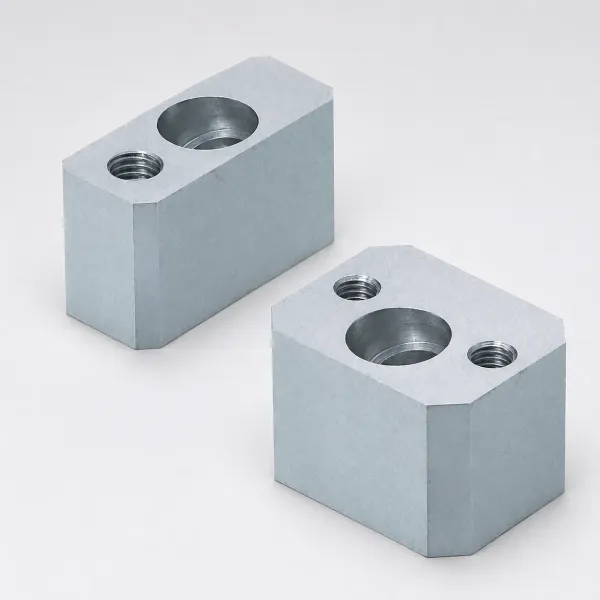
Replace, do not repair, the wear set. Ejector pins, sleeves and return pins are consumables on GF tooling. Design them as standard components from day one, so a worn set swaps in 3-7 days rather than triggering custom remanufacturing. DieStrike ships standard ejector pins, core pins and sprue bushings in that window, which is why GF production programs keep a spare wear set on the shelf sized at 5-10% of pin count.
Cooling Design for Warpage Control
Warpage in GF parts is mostly an orientation problem, but the cooling system decides how much of that orientation survives into the part. Uneven cooling adds differential shrinkage on top of the anisotropic base, and the two effects multiply. The mold-side target is a uniform cavity surface temperature within ±5°C across the entire forming area, which keeps the flow-direction and transverse shrinkage predictable enough for the compensation factors from the previous section to hold.
Channel spacing and mold temperature bands. For GF30 PA66 and GF-PBT, run mold surface temperature at 60-90°C and place cooling channels 3-5x channel diameter from the cavity surface, typically 15-25 mm for 8-10 mm lines. GF-PPS wants hotter steel, 80-120°C, and tighter channel pitch because the higher melt temperature of 280-320°C puts more heat into the block per shot. Under-cooled GF-PPS skins freeze fiber orientation unevenly and the part warps no matter how good the cavity compensation is.
Cool hot spots symmetrically. Thick ribs, bosses and gate areas hold 2-4x the heat of nominal walls. Add baffles, bubblers or conformal inserts to those zones and balance the circuit so the gate end and the far end of the cavity see the same temperature. A 10°C surface delta across a 60 mm GF30 PA66 housing translates to roughly 0.03-0.06 mm of differential shrinkage, enough to tilt a flatness spec on its own.
Cycle time interacts with wear. Shorter cycles raise the average heat load on steel and coatings. A GF program running 15 s cycles puts 2x the thermal cycling into cavity surfaces versus 30 s cycles, and thermal fatigue cracks on H13 typically initiate above 50,000-100,000 cycles in hot zones if surface temperature swings exceed 60°C per shot. Stable cooling protects dimensional consistency and steel life at the same time. Our companion guide on cooling channel design covers sizing in depth.
Mold Life Expectations for GF Resins
SPI tooling classes frame the conversation: Class 101 targets 1,000,000+ cycles, Class 102 targets 500,000, Class 103 targets 250,000. Running GF30+ resins effectively drops every class by roughly one level unless the wear zones are over-spec'd. A Class 102 mold built in P20 that would deliver 500,000 shots on unfilled PP may show gate erosion beyond ±0.01 mm and cavity polish loss by 150,000-200,000 shots on GF30 PA66. The same mold built with hardened inserts and DLC on the wear zones reaches its 500,000-shot target.
What actually ends a GF mold's life. In order of frequency: gate land erosion that shifts fill balance, cavity surface roughening that drags fibers and marks parts, ejector clearance growth that flashes, and thermal fatigue cracking in hot-runner manifolds and gate zones running above 250°C melt contact. Catastrophic failures are rare. The mold dies of accumulated microns, which is why life prediction is a maintenance planning problem, not a steel strength problem.
Design for measurable intervals. Build inspection into the tool: put witness features or datums on gate inserts, record gate size at T1 with a pin gauge to ±0.005 mm, and re-measure every 50,000 shots. On our GF programs we typically see 0.005-0.015 mm of gate land growth per 100,000 shots on hardened steel inserts, and 3-5x less on carbide. When growth passes half the dimensional tolerance of the affected feature, swap the insert. That interval, not a shot-count slogan, is the real mold life number, and it is why hardened inserts must be replaceable rather than welded.
Cost of Hardened Tooling vs Downtime
Hardened steels, replaceable inserts and coatings add a typical 10-25% premium to mold cost. A $60,000 four-cavity GF30 PA66 tool becomes $66,000-75,000. Buyers ask whether the premium is justified. The math says yes on any program above roughly 200,000 shots, and the numbers below show why.
Repair downtime dwarfs the premium. A worn P20 cavity insert needs welding, re-machining, re-polishing and a re-trial: typically 2-4 weeks of downtime for a GF program, or $8,000-20,000 in expedited repair cost plus lost production. A hardened insert swaps in days and costs $300-1,500 per piece. On a connector program shipping 1.2 million parts a year, one avoided cavity repair pays back the entire hardening premium.
Coating payback on wear zones. DLC on gate lands and sliding pins costs $200-800 per component set and extends those zones 2-4x. On a GF45 program, coating the top 10 wear components typically defers the first major service by 150,000-300,000 shots. TD treatment costs more, roughly $1,000-3,000 per core pin set, but survives contact pressures above 2,000 MPa where PVD coatings spall.
Scrap is the hidden line item. Erosion does not announce itself. It drifts fill balance across cavities, and multi-cavity GF molds start producing out-of-window parts weeks before anyone measures the gate. A 1% scrap increase on a 1 million-part program is 10,000 parts, at $0.80-3.00 per connector housing that is $8,000-30,000 a year in pure loss. Hardened, replaceable, measurable wear zones keep scrap flat by keeping gates in tolerance.

DFM Checkpoints for GF Molds
Every glass-filled program should clear the same DFM gates before steel is ordered. These checkpoints catch the failures this article describes at the drawing stage, where corrections cost hours instead of weeks.
1. Material and filler declaration. The RFQ must state resin family, glass percentage and fiber type (chopped vs long glass). A GF15 and GF45 version of the same part need different gate depths, different insert hardness and different shrinkage factors. If the buyer may switch fillers mid-program, the mold must be built to the worst case from day one.
2. Wear-zone map. Mark every surface where melt velocity exceeds 2 m/s: gate lands, runner crossovers, narrow ribs, valve gates and sliding shut-offs. Each marked zone gets an insert, a hardness spec and a coating decision. A GF mold with no wear-zone map is a P20 mold waiting to fail.
3. Directional shrinkage factors agreed before cutting. Flow and transverse factors for the specific resin must be in the cavity model, not applied after T1. Ask for the molder's historical data on the exact grade; datasheet averages hide 0.2-0.4% scatter between compound batches.
4. Insert replacement plan. Confirm that every wear insert can be swapped without disassembling the mold base, and that spares are quoted with the tool. A hardened insert that requires 3 weeks of mold teardown to replace will not get replaced on schedule, and unmaintained wear zones are where scrap rates climb.
5. Cooling verification. Run mold flow or at minimum a thermal balance calculation before steel order. Verify ±5°C cavity surface uniformity at target cycle and check that gate zones have dedicated cooling, since GF gates run hotter and erode faster when thermally soaked.

DieStrike returns DFM feedback within 24 hours, covering exactly these five gates plus venting and ejection review, and builds GF production tooling to ±0.005 mm mold accuracy with IATF 16949 process control for connector OEMs including TE Connectivity, Amphenol and Luxshare.
FAQ
Q1. Can I run glass-filled resin in an existing P20 mold?
For short runs under 50,000-100,000 shots, yes, with expectations managed: gate lands will erode and cavity polish will dull. For production volumes, retrofit hardened inserts (HRC 56-62) at gate and wear zones first. The retrofit typically costs 5-15% of a new mold and multiplies usable life 3-5x.
Q2. What hardness do I need at the gate land for GF30 PA66?
HRC 56-62 through-hardened steel is the minimum for gate lands; carbide is standard above 500,000 shots or for GF45+ loads. P20 at HRC 28-32 shows measurable gate growth, typically 0.01-0.03 mm, within the first 100,000 shots.
Q3. How much does DLC or TD coating add to mold cost, and is it worth it?
DLC adds roughly $200-800 per wear component set, TD about $1,000-3,000. On GF30-45% resins both extend coated zones 2-4x. Any program above 200,000 shots recovers the cost through deferred repair and flat scrap rates.
Q4. Why do my GF parts warp even though the cavity was scaled correctly?
Because glass-filled resins shrink 2-3x more across flow than along it. A single scale factor cannot compensate both directions. Check that directional factors were applied per feature, and verify cavity surface temperature uniformity within ±5°C; a 10°C gradient alone adds 0.03-0.06 mm of differential shrinkage on a 60 mm housing.
Q5. What mold life should I specify for GF-PPS tooling at 1 million shots?
Specify SPI Class 101 construction: H13 hardened to HRC 48-52 cavity and core, carbide or hardened inserts at all gates, DLC or TD on sliding components, and replaceable wear inserts with spares quoted at tool order. Also require gate-size inspection records every 50,000 shots so insert swaps happen on measurement, not on failure.
The Bottom Line
Glass-filled resins punish soft steel, shallow gates and single-factor shrinkage. Hardened inserts at HRC 56-62, deeper edge gates at 0.5-0.8x wall, directional cavity compensation and a measured wear-zone maintenance plan turn a 150,000-shot problem tool into a 500,000-1,000,000-shot asset. DieStrike builds IATF 16949 GF production molds with 24-hour DFM feedback and ±0.005 mm mold accuracy. Send us your GF part drawing for a wear-zone review before you commit to steel.
KEEP READING
Related Reading
Mold Steel Guide: P20 vs H13 vs S136
Compare hardness, polishability and cost of the three most common mold steels for cavities and cores.
Read articleArticleDLC Coating for Mold Components
How diamond-like carbon coatings cut friction and abrasive wear on pins, inserts and sliding surfaces.
Read articleArticle7 Gate Design Best Practices for Balanced Filling
Gate sizing, location and land rules that prevent jetting, weld lines and premature erosion.
Read articleServiceMold Design & DFM
24-hour DFM feedback on steel selection, gating, cooling and tolerance feasibility before tool cut.
Read articleNEXT STEP
Ready to Start Your Mold?
Send us your element dimensions or part numbers — our team responds within 24 hours with pricing and lead time.

Written by
Ray ChanMold Buyer's Guide Author · Precision Mold Manufacturing Specialist. Ray helps global importers, distributors and OEMs source factory-direct molds and mold parts.