
How to Design Molds for Metal Injection Molding: MIM Tooling
Table of Contents
The first MIM mold ordered from a general plastic tool shop usually fails at the furnace, not at the press. Sintering removes 12-20% of every linear dimension, so a cavity cut to the drawing size delivers parts that shrink out of tolerance in both directions. The buyer then pays twice, once for the tool and again for a cavity weld or a new insert. Metal feedstock carries 40-60 vol% metal powder through a gate that has to be wider, shorter and tougher than any resin gate. The mold must be designed around debinding, sintering and abrasive wear from the first steel cut.
This guide covers the eight mold-side decisions that decide whether a MIM tool produces sintered parts inside tolerance. Shrinkage compensation sets the cavity size. Gate and runner geometry controls powder-binder separation. Vent depth controls density. Steel choice controls how long the cavity survives the feedstock. Ejection geometry controls whether the weak green part survives the drop into the tray. Each section below carries the numbers used on the bench.
The Snapshot
- Sintering shrinkage runs 15-17% for 316L, 13-15% for 17-4PH and 12-14% for iron-based alloys (typical figures). Cavity dimensions are back-calculated from the sintered target.
- MIM gates run Ø0.8-1.5 mm with a 0.5-1.0 mm land, roughly 40-60% larger than the plastic gate for the same part, to keep shear low.
- Cavity and gate insert steel is hardened to HRC 58-62, with carbide inserts at high-wear gates and PVD or DLC coating on sliding faces.
- Draft is set at 1-2° minimum with a large ejection area, because a green part holds only about 30-50% of sintered strength.
- Typical MIM tools run 4-16 cavities for parts under 20 g, held to ±0.005 mm mold dimension accuracy (DieStrike tooling capability).
Why MIM Tooling Is Not Plastic Tooling
A MIM feedstock is a metal powder of 5-20 µm suspended in 35-45 wt% binder. The mix behaves like a heavily filled polymer with a melt viscosity 5-10 times that of unfilled resin at the same temperature. Barrel temperatures sit between 150 °C and 200 °C and mold temperatures between 40 °C and 80 °C, which keeps the binder stiff enough to hold shape. Injection pressures reach 80-150 MPa, well above the 40-80 MPa of a typical resin tool.
That difference changes every downstream mold decision. A small gate shears the feedstock and separates powder from binder, which produces density gradients that survive sintering as size variation. Thin cores deflect under the higher pressure and bend green parts on ejection. Sharp internal corners create dead zones where powder and binder move at different speeds. A plastic tool that passes a mold flow study can still fail here, because most flow models do not carry a filled-feedstock viscosity curve.
Green part reality. After molding, the part is a compact of powder held by binder, with roughly 30-50% of the strength of the sintered part. It cannot take the ejection forces a resin tool applies, and it cannot be dropped, vibrated or clamped hard. Mold design follows from that single fact more than from any process parameter.
Shops that build both tool types treat MIM as a hybrid. The steel, alignment and cooling package follows injection mold practice, run under IATF 16949 process control at the cavity level. The flow path, venting and ejection follow powder metallurgy practice. DieStrike builds MIM and plastic cavities on the same floor, with mold dimension accuracy of ±0.005 mm and mold component geometry held to ±0.002 mm.
Shrinkage Compensation: Sizing the Cavity for 12-20% Loss
Every cavity dimension is a reverse calculation. If the sintered target for a length is 20.00 mm and the alloy shrinks 16% linearly, the cavity is cut at 23.81 mm. That figure is the target for the mold, not for the press operator. Get it wrong by 1% and a 20 mm feature lands 0.2 mm out, which is 4 times a typical ±0.05 mm print tolerance.
Suppliers publish shrinkage as a range rather than a single value because powder lot, binder fraction, injection density and the sintering profile all move it. 316L typically lands between 15% and 17%, 17-4PH between 13% and 15%, and iron-based alloys between 12% and 14%. A cavity cut at the middle of the range then needs the furnace to repeat within about ±0.3% to keep sintered parts inside a ±0.05 mm band on a 15 mm feature.
| Alloy | Typical Linear Shrinkage | Cavity Size for a 10.00 mm Target | Manufacturability Note |
|---|---|---|---|
| 316L stainless | 15-17% | 11.76-12.05 mm | Corrosion resistant, good for medical and food parts |
| 17-4PH stainless | 13-15% | 11.49-11.76 mm | Hardenable to HRC 40-48 after sintering, watch distortion |
| Iron-based, low alloy | 12-14% | 11.36-11.63 mm | Lowest shrink, best dimensional stability for structural parts |
| Tungsten heavy alloy | 16-18% | 11.90-12.20 mm | High density, needs generous gate and slow fill |
| Soft magnetic alloy | 14-16% | 11.63-11.90 mm | Tolerances drive the compensation model, magnetic property drives the sinter profile |
← swipe to scroll →
Table note: Shrinkage ranges are typical industry figures for standard MIM feedstocks. Every production lot is confirmed by a trial measurement, and the cavity math assumes uniform shrinkage in all axes.
Mold makers leave adjustment stock rather than cutting to the exact predicted value. Standard practice is to hold 0.3-0.5% of extra material on critical dimensions for the first trial, then cut to final size after measuring a sintered T1 sample on the CMM. That plan keeps a first article one EDM pass from the target instead of one weld away from scrap. It also keeps the correction inside the hardened cavity, so no soft weld sits in the wear path.
Where the number really comes from. The reliable source is a trial cavity block machined with a dimension grid, molded, debound and sintered alongside production samples. Sectioned parts measured on a CMM give the true shrinkage vector for that powder, binder and furnace combination. Published alloy tables are the starting point, not the final answer. For the broader rules on how rates and trial corrections are managed, see the five shrinkage compensation rules used across plastic and MIM tooling.
Anisotropic Shrinkage and Flow Direction
Feedstock flows along the fill direction, so powder particles align slightly with that flow and the part shrinks differently along flow than across it. The difference is usually small, 0.2-0.6 percentage points, but it is enough to break a ±0.05 mm tolerance on a 15 mm feature. In a 10.00 mm part that spread equals 0.02-0.06 mm.
Porosity from gate shear, weld lines where two flow fronts meet, and density gradients at the last-filled region all change local shrinkage. Warp in a 30 mm MIM part can reach 0.1-0.3 mm when the gate sits at one end and the fill is unbalanced. Gate placement therefore controls dimension, not just fill quality. Moving a gate from one end of a plate to the centre can halve the bow on the sintered part.

A useful design rule is to orient the critical dimension along the fill direction on purpose. That direction usually shows the most repeatable shrinkage because the density gradient follows the same vector every cycle. Dimensions that sit across the flow are then treated as secondary and given looser print tolerance or a post-sinter machining allowance. Where two critical dimensions cross, a cavity with multiple gates or a symmetric fill pattern is the usual fix.
Core and cavity differ. A cavity surface defines the outside of the part and a core pin defines a bore. Bore shrinkage often runs 0.3-0.5 percentage points higher than outer-wall shrinkage because the core side cools differently and the powder packs at a different rate. Bore dimensions on MIM parts are therefore quoted with a wider band, and a core pin held to ±0.002 mm geometry still needs a separate compensation factor in the cavity model.
Gate and Runner Design for Metal Feedstock
MIM gates run Ø0.8-1.5 mm against Ø0.5-1.2 mm for the same part in a plastic tool. The wider gate lowers the shear rate at the narrowest point, and shear rate is the main control on powder-binder separation. A land length of 0.5-1.0 mm keeps the gate short, cuts pressure loss, and leaves a witness small enough to remove by hand before debinding.
Runners are short and generous, typically Ø3-5 mm, because pressure drop scales with length at a viscosity 5-10 times that of resin. A long cold runner also cools the feedstock and raises the risk of a short shot on the last cavity. Where geometry allows, a hot runner holds the feedstock at 150-190 °C up to the gate, but the valve pin, gate insert and manifold seat all sit in the abrasive path and need hardened steel or carbide.
A gate that is too small shows up in three ways: short shots at 5-10% lower fill pressure, visible flow marks on the green part, and sintered density 0.5-1.5% lower near the gate after the powder-starved zone sinters. A gate that is too large raises the vestige height past 0.5 mm and forces a secondary operation. The working window between those two failure modes is narrow, which is why gate diameter is usually set from a trial rather than a table alone.

Runner balance matters more than in plastic. An unbalanced runner in a 8-cavity MIM tool produces cavity-to-cavity weight spread of 1-3%, which turns into 0.2-0.5% size spread after sintering. Weighing green parts is the quickest check, because weight tracks density and density tracks shrinkage. Balanced runner geometry plus a natural or full round runner section keeps that spread under 1%.
Venting for 40-60 vol% Metal Powder Feedstock
Feedstock carries 40-60 vol% metal powder, so only the binder fraction can compress. Air that cannot escape at the last-filled point stays trapped and shows up as a short shot, a density dip, or a blister that opens during debinding. Venting is therefore a density control, not only a burn-mark control. A 0.01-0.03 mm vent depth and 3-5 mm vent width at the parting line is the working range for most MIM tools.
Vents belong at the last-filled point of every cavity and every runner end, spaced 25-50 mm apart along the fill perimeter. A MIM tool typically needs 2-3 times as many vents as the equivalent plastic tool, because the feedstock releases air more slowly at the same fill speed. Ejector pins and core pins act as secondary vents when their clearance is set at 0.01-0.02 mm per side, which adds venting without extra parting-line work.

A blocked vent shows itself within a few hundred shots. The trapped gas heats to 300-500 °C under compression and scorches the binder, which leaves a dark patch that survives debinding as a carbon stain on the sintered surface. An under-vented cavity also fills short by 2-5% in volume, which reads as a 2-5% low green weight on the scale. A low green weight almost always means low sintered density and a part that misses its dimensional target.
Vent maintenance is a schedule item. Feedstock leaves binder residue in every vent, and residue narrows the gap within 20,000-50,000 shots. Cleaning vent lands with a brass scraper and solvent at each preventive maintenance stop keeps the depth in range. Any vent that reads under 0.01 mm deep with a depth gauge needs recutting before the next run. The full schedule for vent cleaning, gate inspection and steel checks is covered in the mold maintenance program and applies to MIM tools with a shorter cycle interval than plastic.
Vacuum-assisted venting is the option for high-cavity MIM tools, 8 cavities and above, where parting-line vents alone cannot clear the runner in the fill window. A sealed vacuum plate pulls 200-500 mbar on the cavity before injection and cuts trapped-gas defects to near zero on thin-wall or long-flow parts. The cost sits in the added plate and seal package, and the payback comes from a scrap rate that drops from 0.5-2% to under 0.3% in the first year.
Steel Selection and Wear in MIM Molds
MIM feedstock is abrasive in a way that resin never is. Metal particles of 5-20 µm hardness scouring a gate at 80-150 MPa behave like a light lapping slurry. Cavity and gate steel for a production MIM tool is therefore hardened to HRC 58-62, not the HRC 30-34 typical of a pre-hardened plastic cavity. Tool steels such as H13, 1.2343 or a powder metallurgy grade with high vanadium content hold that hardness with enough toughness for the gate land.
The gate is the first component to wear, because it sees the highest velocity and the sharpest edge. A hardened steel gate insert on a production MIM tool typically holds size for 50,000-200,000 shots before the land erodes enough to change fill. A carbide gate insert with a polished entry runs 3-5 times that life, which matters on a 16-cavity tool where one gate change stops the whole press. Gate inserts should be replaceable from the parting line without pulling the cavity block.
| Mold Feature | Plastic Tool Typical | MIM Tool Typical | Why It Changes |
|---|---|---|---|
| Gate diameter | Ø0.5-1.2 mm | Ø0.8-1.5 mm | Feedstock viscosity 5-10 times resin, low shear prevents powder separation |
| Runner diameter | Ø2-4 mm | Ø3-5 mm | Pressure drop and cold-start risk on a filled melt |
| Vent depth | 0.02-0.03 mm | 0.01-0.03 mm | Binder flash control, 2-3 times more vent locations |
| Cavity hardness | HRC 30-34 (P20) | HRC 58-62 | Abrasive metal powder erodes soft steel at the gate and core |
| Draft angle | 0.5-1° | 1-2° minimum | Green part carries only 30-50% of sintered strength |
| Mold temperature | 40-90 °C | 40-80 °C | Binder must stay stiff enough to resist ejection shear |
← swipe to scroll →
Table note: Values are typical industry figures for production MIM tooling at part weights under 50 g. Hardness and draft are set per part geometry, not applied as blanket rules.
Surface treatment adds life where machining alone cannot. PVD coatings such as TiAlN or CrN on core pins, slides and ejector surfaces cut friction and galling against the binder-rich green part. DLC coatings take that further on sliding components in abrasive service of 100,000 shots and above, with a coating thickness of 2-5 µm that does not disturb the tolerance band. Coated ejector pins in MIM tools show measurably lower drag and less bore wear than uncoated pins of the same steel, which is the same payback pattern seen in standard component service.
Alignment hardware should be sized for the abrasive environment as well. Guide pins and bushes in a MIM tool run dry of resin lubrication, so bushing bores wear faster than in a plastic tool. Hardened and coated leader pins with replaceable graphite or bronze-plated bushes hold alignment for the full 200,000-500,000 shot expectation of a well-built MIM tool. Alignment drift is the quiet failure here, because a 0.02 mm loss of alignment turns into a visible offset, flash at a shut-off and a scrapped insert.
Ejection and Draft for Low Green Strength
A green MIM part holds only about 30-50% of sintered strength, so ejection is designed around the weakest moment in the process. Draft of 1-2° minimum on every wall and 1.5-2.5° on texture or deep cores lets the part leave with a light push. Walls drafted at 0.5° show drag marks, and drag marks on a green part are permanent because nothing refills them during sintering.
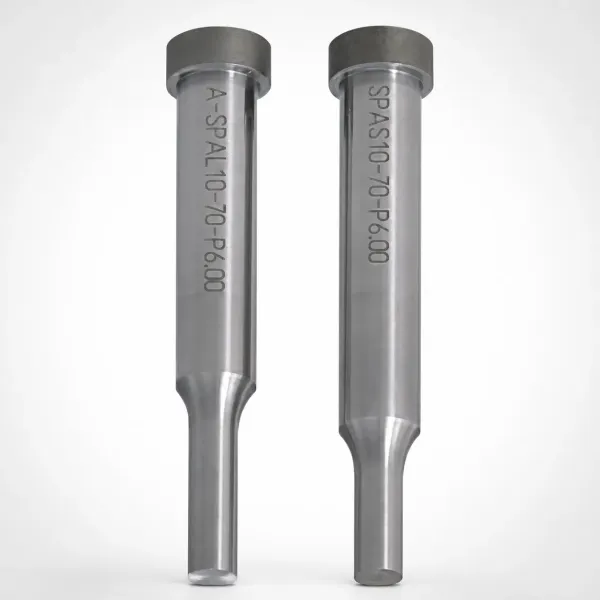
Ejector area must be generous. A green part that sees 2-5 MPa of local ejection stress tears, while the same part in resin would tolerate 20 MPa. Design practice is to use the largest practical ejector pads, plates or sleeves rather than small pins, and to keep ejector contact area at 5-10% of the projected part area as a floor. Sharp pin tips are avoided entirely, and every ejector needs a radius or chamfer of 0.2-0.5 mm on the contact edge.
Ejection force scales with the part's hold on the core, so core draft matters most. A core drafted at 1° on a 20 mm deep bore releases with roughly half the force needed at 0.25° draft. Undercuts, threads and internal ribs should be designed out where possible. Where they are needed, collapsible cores or side actions carry the same low-force rules, and the timing must be set so nothing pulls on the part before the sliders clear.
Cooling and demolding temperature. MIM tools run mold temperatures of 40-80 °C and the green part must be cool enough to hold its edges on exit. Core-side cooling matters more than cavity-side cooling, because a warm part sticks to the core and stretches. Baffles and bubblers in tall cores bring core surface temperature within 5-10 °C of the cavity, which is the practical target for a stable ejection force.
Part handling after ejection is part of the tool design too. A 10 mm part weighing 3 g can be damaged by a 100 mm drop, so the take-out path from the parting line to the tray needs a short chute or a robot with a compliant gripper. Molds designed for automatic take-out include a pick point and a flat pad for the gripper, and that pad has to be placed inside a region that tolerates a light witness mark.
Cavity Count and Layout for Small MIM Parts
MIM parts are small, most under 20 g, so tools run more cavities than comparable plastic tools. A working range is 4-16 cavities for most production MIM tools, and 16-64 cavities for very small parts under 1 g. The upper limit is set by fill balance, runner volume and the ability to hold cavity-to-cavity size spread under 0.3% after sintering.
Runner volume is the first constraint on cavity count. A cold runner system in a 16-cavity tool can consume 40-60% of the shot weight, and that scrap goes back into feedstock recycling rather than straight to a customer. Thermal gating with a hot runner reduces the loss but adds gate wear, so the choice is a cost trade, not a default. At 1 million shots a year, the difference between a 45% runner scrap and a 15% runner scrap is significant feedstock volume.
Layout should be symmetric around the sprue, with equal runner length to every cavity. A cavity that sits 20 mm further from the sprue sees measurably lower fill pressure and produces a lighter green part, which after sintering lands at a different size. Symmetric layout plus balanced runner section keeps the cavity-to-cavity weight spread under 1%, which is the practical pass line when green parts are weighed as a QC check.
Machine fit. Cavity count has to fit the press. Projected area for all cavities plus the runner, multiplied by cavity pressure in the 40-80 MPa range, must stay inside the machine's available clamp force with a 20-30% margin. A 16-cavity MIM tool can otherwise require a machine larger than the one the plant owns, and that mismatch usually appears late in the project when the tool is already quoting. Checking shot size against barrel capacity of 20-80% of the barrel rating is the second fit test.
Inserts and cavity numbering belong in the same decision. Building each cavity as a replaceable insert costs 10-20% more upfront but makes single-cavity repair possible without recutting the whole block. Laser-marked cavity numbers, an insert ID and a date insert add traceability, so a sintered part that misses tolerance can be tied back to one cavity and one insert revision.
Mold Life, Maintenance and Refurbishment Cycles
A well-built MIM tool runs 200,000-500,000 shots before a major refurbishment, which is shorter than the 500,000-1,000,000 shots a hardened plastic tool reaches. The gap comes from abrasive wear rather than fatigue. Every shot drags metal powder across the gate land, the core surfaces and the ejector clearance, so the wear rate is roughly proportional to shot count and part weight.
Wear shows up first at three points. The gate land grows, which lowers fill pressure and changes green density near the gate. Core pins lose diameter at the entry radius, which shows as a taper on the molded bore. Ejector bores open up, which allows drag marks and, eventually, flash around the pin. Inspection intervals for MIM tools are therefore tied to shots, with a visual gate and core check every 20,000-50,000 shots and a dimensional check every 100,000 shots.
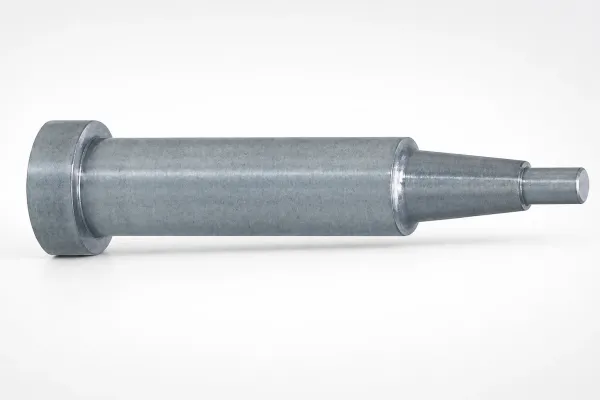
Refurbishment is a planned job, not an emergency. Recutting a gate land or replacing a gate insert takes hours, while a crash from a broken ejector pin can take the cavity block out of service for days. The practical program keeps one spare gate insert per tool, one spare core pin set and a documented wear limit for each critical feature. That structure lets the shop change a worn insert inside a normal maintenance window instead of pulling the tool off the press mid-run.
Surface protection pays back inside one refurbishment cycle. A nitrided or PVD-coated cavity face resists powder erosion far better than an untreated face of the same steel, and the tool stays in tolerance longer. DLC stands out on sliding parts, where coating thickness of 2-5 µm cuts friction and galling without changing the fit. Coating grades and payback are compared in the DLC coating guide for mold components. The condition of leaders, slides and springs should be checked at the same time as any coating decision, so refurbishment once per cycle instead of three times. The mold maintenance schedule for weekly, monthly and annual work applies directly here with a shorter interval in shot count.
Repair methods for a worn MIM cavity. Laser welding is the standard repair for a damaged gate land or shut-off, because heat input stays local and the surrounding hardness survives. TIG welding carries more heat and is a better fit for larger block repairs on non-critical faces. After any weld repair, the cavity goes back to the EDM and the surface is repolished to the original finish. A repaired cavity is re-measured on the CMM before it goes back into the press, since a 0.02 mm shift in the gate area changes fill and shrinkage on that cavity alone.
From Green Part to Sintered Part: The Handoff
Debinding removes 35-45 wt% of the part as binder before any metal-to-metal bonding happens. Solvent debinding, catalytic debinding and thermal debinding all run at different temperatures and times, and each one changes the shrinkage the mold was designed for. The compensation model in the cavity therefore belongs to a specific binder system, not to metal injection molding in general. Switching binder suppliers without a trial cavity block usually reopens the whole tolerance question.
Sintering then runs at 1,250-1,400 °C in hydrogen, vacuum or a partial-pressure atmosphere for a hold of 60-120 minutes. That is where the 12-20% linear shrink happens and where density reaches 95-99% of theoretical. Furnace run-to-run variation of ±0.3% is what stands between the mold target and a shipped part, so the furnace load position and the setter plate design matter as much as the cavity size.

As-sintered tolerances for typical MIM parts sit at ±0.3-0.5% of the nominal dimension, which equals roughly ±0.05 mm on a 10-15 mm feature and ±0.15 mm on a 30-50 mm feature. Tighter callouts need secondary machining, and the mold design should decide which dimensions fall on each side of that line. Holding a dimension as-sintered costs mold accuracy, while holding it by machining adds $0.30-$2.00 per part depending on the feature count.
Secondary operations available after sintering include coining or sizing in a die, CNC turning and milling, grinding, thread tapping, and heat treatment. A 17-4PH part can be aged to HRC 40-48 after sintering, with distortion of 0.05-0.15 mm that the print tolerances must absorb. Where a part needs both a tight bore and an as-sintered profile, the usual split is a machining allowance of 0.2-0.4 mm on the bore with the profile left to the mold.
What the mold has to leave behind. Traceability starts in the cavity. Cavity numbers, an insert revision ID and a date insert let a sintered part be traced to one cavity, one insert revision and one molding window. That link is what makes a tolerance investigation possible, because the same sintered size can come from a worn gate, a cold cavity or a furnace position. DieStrike builds MIM and plastic tooling under IATF 16949 process control, with DFM feedback inside 24 hours and injection mold lead times of 2-5 weeks for tooling through its injection mold manufacturing service, so a shrinkage trial and the compensation change land in the same project window.
Buyers should also plan the first article flow before the tool is cut. A T1 sample that goes through debinding and sintering before the CMM report is the only sample that proves the compensation model. Green-part measurement is useful for density and weight checks, but it cannot confirm a sintered dimension. Building the trial plan around the sintered sample saves a full tool revision on most MIM programs.
FAQ: MIM Mold Design Questions
Q1. How much do I oversize a MIM cavity for sintering shrinkage?
Oversize by the alloy shrinkage rate: 15-17% for 316L, 13-15% for 17-4PH and 12-14% for iron-based alloys, typical figures. A 10.00 mm sintered target becomes an 11.76-12.05 mm cavity for 316L. Confirm the rate with a trial cavity block before cutting the production block, because binder system and furnace profile move the number by 0.5-1 percentage point.
Q2. Can an existing plastic injection mold be converted to run MIM feedstock?
Rarely, and only with real risk. A plastic tool usually has gates of Ø0.5-1.2 mm, vents of 0.02-0.03 mm and cavity steel at HRC 30-34, all outside the working range for abrasive filled feedstock. Conversion needs new gate inserts, reworked vents, hardened cavity steel and larger ejection area, which typically costs 40-60% of a new tool while carrying the old base's wear history.
Q3. What draft angle do MIM parts need?
Use 1-2° minimum on all walls, 1.5-2.5° on deep cores and 2-3° on textured surfaces. The green part holds only 30-50% of sintered strength, so it cannot be forced off a shallow draft without drag marks. Drag marks are permanent because sintering cannot refill a torn green surface.
Q4. How many cavities should a MIM mold have?
Run 4-16 cavities for parts under 20 g and 16-64 cavities for parts under 1 g. The limit is not machine size alone. Runner scrap of 40-60% of shot weight in a 16-cavity cold runner tool, plus a cavity-to-cavity size spread that must stay under 0.3% after sintering, usually decides the final count.
Q5. What tolerance can MIM hold as-sintered?
Plan on ±0.3-0.5% of nominal as-sintered, which is about ±0.05 mm on a 15 mm feature. Tighter callouts of ±0.01-0.02 mm require secondary machining after sintering. Mold dimensions held to ±0.005 mm and mold component geometry held to ±0.002 mm give the compensation model enough headroom to land inside that band.
The Bottom Line
MIM mold design lives or dies on shrinkage compensation, gate shear and abrasive wear. Cut the cavity from a published shrinkage table alone and expect one revision. Build the compensation model with a trial block, harden the gate, plan inserts and vents as wear parts, and a MIM tool holds tolerance for 200,000-500,000 shots. Send drawings for a DFM review before any steel moves at contact DieStrike.
KEEP READING
Related Reading
5 Shrinkage Compensation Rules for Mold Design
Shrinkage compensation decides mold accuracy. Five rules: material rates from 0.3% to 2.5%, cavity sizing math, and trial correction.
ArticleDLC Coating for Mold Components: When It Pays Off
DLC coating on core pins, gates and slides cuts abrasive wear and galling. Cost per component and when the payback lands.
ArticleHow to Maintain a Mold: Weekly/Monthly/Annual Schedule
Weekly water, pin and gate checks, monthly lube and vent cleaning, annual teardown with steel recertification and wear limits.
ServiceMold Design and DFM
DFM feedback within 24 hours on wall thickness, draft, gate location and shrinkage compensation before any steel is cut.
NEXT STEP
Ready to Start Your Mold?
Send us your element dimensions or part numbers — our team responds within 24 hours with pricing and lead time.

Written by
Ray ChanMold Buyer's Guide Author · Precision Mold Manufacturing Specialist. Ray helps global importers, distributors and OEMs source factory-direct molds and mold parts.