
How to Design for Micro Molding: Tooling Rules for Sub-Gram Parts
Table of Contents
A 0.4 g gear with a 0.15 mm wall sat on the DFM desk. The drawing carried a ±0.005 mm true position call-out on a hole you could not see without magnification. The first quote came back at 2.8x the cost of the same part scaled to 50 g, and the buyer's first reaction was to cut the cavity count from 16 to 4 to save tooling. That single decision raised the per-part cost by roughly 40 percent and locked in a runner scrap problem the process could never fix. The tool was the product, and the tool was designed wrong before steel arrived.
Micro molding looks like a molding problem, and on the press it behaves like one. But every constraint that makes micro parts hard starts inside the mold: the 0.1 mm gate, the 0.3 mm ejector pin, the 0.005 mm vent depth, and the polished cavity face that a careless hand can wipe past tolerance. This guide reads from the mold side. It covers the part band that qualifies as micro, the tolerances a micro mold can hold, cavity machining, steel and finish, gating and runner balance, ejection and draft, venting and shrinkage, cavity strategy, and the DFM red flags to clear before steel is ordered. Injection parameters appear only where they decide a tooling rule.
All figures in this guide are industry-typical values from micro tooling practice and from DieStrike's precision connector mold programs. Verify every number against the resin datasheet, the mold flow analysis, and trial data before cutting steel. Datasheets and trials always override rules of thumb.
The Snapshot
- The micro band means parts under roughly 0.5-2 g shot weight, or features below about 0.5 mm with walls of 0.1-0.5 mm and holes of 0.05-0.3 mm.
- Critical part tolerances run ±0.005-0.01 mm typical, and the cavity compensation has to come from trial shrinkage data, not a datasheet average.
- Cavity corners below 0.05 mm are EDM territory. Wire EDM runs 0.02-0.03 mm wire, and micro end mills for finishing start at 0.1-0.3 mm diameter.
- Gates run 0.1-0.5 mm wide with 0.2-0.5 mm lands, and a cold runner can outweigh the parts it feeds by 5-10 times.
- Ejector pins start at 0.3-1.0 mm diameter with 0.005-0.01 mm sliding clearance, while draft stays at 0.5-2 degrees per side.
The Part That Weighs Less Than the Sprue
The name of the problem is in the ratio. A cold sprue for a small press runs 1-3 g typical, while the micro part it feeds weighs 0.5 g or less. On a 16-cavity micro connector tool, the full cold runner tree can outweigh the sum of all 16 parts by 5-10 times, which means the runner, not the part, controls fill timing, pressure drop, and cycle length.
That ratio rewrites the mold designer's job. In a conventional tool the cavity is the main flow event and the runner is plumbing. In a micro tool the cavity is a few percent of the runner volume, and the mold must dose a precise small charge through a gate the size of a hair while the runner stays hot enough to keep packing. Every runner rule from conventional design still applies, but the consequences multiply. A runner balance error that costs a conventional part 2 percent of fill costs a micro cavity a short shot.
Relative errors are equally brutal. A 0.05 mm machining mismatch on a 0.3 mm rib is roughly 17 percent of the feature, while the same error on a 3 mm rib is under 2 percent. Standard tooling tolerance thinking in the 0.01-0.02 mm class does not survive contact with a 0.1 mm wall. The mold shop has to hold micron-class geometry on features that are themselves only tens of microns across.
Designers who start from the part side ask which resin flows best. Designers who start from the mold side ask what the cavity, the gate, and the ejector system can physically do at that size. This guide is written for the second question, because the first one gets answered at the press and the second one gets answered in steel.
What Counts as Micro Molding
Micro molding is not a machine size and it is not thin-wall molding of a large part. It is a feature band. Parts qualify as micro when shot weight falls under roughly 0.5-2 g typical, or when governing features drop below about 0.5 mm: walls of 0.1-0.5 mm, holes of 0.05-0.3 mm, and ribs, slots, or gear teeth in the same class.
The parts that live in that band cluster in three families. Micro connectors carry terminal pitch and insulator geometries well under 1 mm. Micro gears run tooth modules below about 0.3 mm typical with bores that need core pins in the 0.3-0.8 mm range. Medical device components for drug delivery, diagnostics, and surgical instruments use wall sections of 0.1-0.5 mm and features down to 0.05 mm, and they follow the compliance path described in our medical injection molding guide. Watch the direction of that list: the parts are small, so the cavities, cores, gates, and ejectors are all smaller than anything a conventional mold shop stocks.
Feature band is the better definition than shot weight, because shot weight alone is misleading. A 1 g part with 2 mm walls is easy. A 1 g part with a 0.12 mm wall and a 0.05 mm through hole is a micro molding project. The wall and hole sizes set the tooling difficulty, and they are the numbers to put on the RFQ.
The same band explains why micro molding carries its own cost structure. Standard cavity inserts, ejector pins, and core pins do not shrink below about 0.5 mm useful diameter in off-the-shelf catalogs, so micro tools lean on custom ground pins, micro EDM electrodes, and hand-finished cavities. That is the premium the next sections price out.
Tolerances: What a Micro Mold Can Actually Hold
Separate the steel tolerance from the part tolerance before quoting anything. A precision mold shop holds mold dimensions to ±0.005 mm and machined mold components to ±0.002 mm geometry, which is DieStrike's standard capability band. But the molded part does not inherit that number. Part tolerance is the sum of steel geometry, thermal expansion, shrinkage variation, and measurement error, and at micro scale shrinkage and measurement dominate.
Critical micro part features are commonly called at ±0.005-0.01 mm typical. On a feature that is itself 0.3 mm, that tolerance is 1.5 to 3 percent of the feature, which is tighter than the resin can hold without disciplined cavity compensation. Shrinkage on a 1 mm feature at 1.5 percent typical unfilled semicrystalline rates is 0.015 mm, already larger than a ±0.005 mm tolerance band. Glass-filled liquid crystal polymer shrinks less, roughly 0.1-0.5 percent typical, but it shrinks differently in flow and cross-flow directions, so the compensation has to be directional, not a single scale factor.
Thermal geometry is the quiet budget eater. Mold steel expands at roughly 11-12 µm per meter per degree Celsius typical. A 100 mm cavity plate that drifts 10 °C between production and measurement moves about 0.012 mm, which is larger than many micro tolerances. That is why micro tools are measured in a temperature-controlled room at 20-23 °C and why cavity compensation is locked after trial data, not after a drawing review.
Apply tolerance discipline at the drawing stage. Call ±0.005-0.01 mm only on features that function, like bores that receive mating pins, gear pitch diameters, and connector sealing surfaces. Let cosmetic and non-critical geometry breathe. Every tightened call-out costs machining time, EDM electrodes, polishing control, and measurement time, and on a micro tool those costs compound across every cavity.
Cavity Machining: Micro EDM and Micro Milling
Micro cavities are cut, not carved. Two processes carry almost all micro geometry: micro milling with end mills of 0.1-0.3 mm diameter, and micro EDM in both sinker and wire form. The choice between them is a corner radius, an aspect ratio, and a finish decision, and the trade-offs are covered in detail by our hard milling vs EDM comparison. In the micro band the practical lines are sharper than in conventional work.
Micro milling wins where the geometry is open enough for a cutter and the steel is machinable. End mills of 0.1-0.3 mm diameter run on high-speed spindles, typically 40,000-60,000 rpm, and they cut slots, ribs, and cavity floors with good surface finish. The limits are stiffness and reach. A 0.15 mm end mill has a practical depth-to-diameter ratio of roughly 2-3 to 1, and any spindle runout above a couple of microns breaks small cutters or smears the cavity wall. Long thin pockets therefore go to EDM.
Sinker EDM carries the deep, narrow, and blind geometry. Machined or formed electrodes as small as 0.05-0.1 mm across plunge details that no cutter can reach, and CNC orbital movement cuts pockets with depth-to-width ratios above 5 to 1. The trade is surface. Finish-cut EDM leaves a recast white layer typically 0.001-0.005 mm thick that must be polished off where demolding or optics demand a clean face, and every electrode wears during the burn, so the shop compensates by measuring the first cavity and adjusting the program.
Wire EDM does the through geometry. Wire of 0.02-0.03 mm diameter cuts slots, shut-off edges, core pin blanks, and cavity forms with corner radii limited by the wire radius plus the spark gap, practically in the 0.02-0.05 mm class achieved. Our wire EDM for mold making guide covers accuracy and surface in full. For a micro tool the wire cut is often the only way to hold a true internal corner on a hardened insert, because no end mill radius and no grinding wheel can enter it.
| Micro Cavity Feature | Typical Size | Primary Machining Method | Practical Result |
|---|---|---|---|
| Internal corner radius | 0.02-0.05 mm achieved | Sinker EDM with finish electrode | Radius set by electrode form and wear, then polished |
| Slot, rib or channel width | 0.1-0.3 mm | Micro milling, 0.1-0.3 mm end mills | Depth-to-width about 2-3 to 1, Ra finish to sub-micron |
| Through slot or thin shut-off | Down to 0.05-0.1 mm width | Wire EDM, 0.02-0.03 mm wire | Corner radius from wire radius plus spark gap |
| Deep narrow pocket, blind detail | Depth over 5 times width | Sinker EDM, CNC-orbited electrode | Electrode wear 0.1-1% typical, recast layer removed |
| Drafted polished cavity wall | Ra 0.05-0.2 µm | Mill or EDM, then hand polish | Polish must not break ±0.005 mm steel geometry |
← swipe to scroll →
Table: Typical micro cavity feature sizes and the machining methods that produce them. Absolute capability varies with steel hardness, machine condition, and operator skill. Verify against the quoting shop's actual records.
Cutting order matters as much as method. Machine the cavity in soft or prehardened stock, or machine after heat treatment in the hardened state, and the distortion budget changes completely. Hard milling of a 48-58 HRC insert holds geometry that heat treatment would move, which is why micro tooling increasingly skips the soft-machining step. The steel is cut once, at final hardness, and measured once.
Steel, Hardness and Surface Finish
Micro tool steel selection starts with two jobs: holding a polished edge at a tiny scale and resisting the corrosion that kills a 0.005 mm vent. Stainless grades like S136 and 420, plus powder metallurgy tool steels, dominate micro cavities because they do both. The 420-class stainless grades run at roughly 48-52 HRC typical after hardening, while powder steels reach the 56-62 HRC range, and the practical micro tooling band sits at 48-58 HRC typical for most programs.
Why not always go harder? Because hardness and polishability pull in opposite directions. A 0.1 mm rib in a 58 HRC powder steel resists wear and deformation over hundreds of thousands of cycles, but that same carbide-rich structure is slower to machine and harder to hand finish. Where corrosion resistance matters more than wear, as it does in medical-adjacent tooling that sees humid cleanroom storage, S136-class stainless at 48-53 HRC typical wins because it polishes to a mirror and does not rust in a vent slot.
Surface finish is a demolding tool, not decoration. Cavity faces that must release a 0.1 mm wall without sticking, or that form optical surfaces, are polished or EDM-finished to Ra 0.05-0.2 µm typical. The polish progression runs through diamond compounds down to the 0.25-1 µm grit class, and the final pass direction follows the draw so the part releases cleanly.
Polish is also the top tolerance risk in the whole tool. Hand polishing a 0.05 mm corner radius opens the corner into a flat, and working a 0.15 mm rib face for ten minutes can remove enough steel to shift the rib width by several microns. Micro cavities are therefore polished in controlled passes with geometry checks between stages, not finished by feel. Where the part needs extreme release on a deep core, the finish is verified on the steel and again on trial parts before the cavity is accepted.
Gating and Runner Balance at Micro Scale
Gate geometry at micro scale is measured in tenths. Pinpoint and submarine gates run 0.1-0.5 mm wide typical with land lengths of 0.2-0.5 mm, sized against a wall of 0.1-0.5 mm. The gate is the smallest cross-section in the system and the last thing to freeze, which is how it packs the cavity. On a 0.2 mm wall, a gate near 0.15-0.3 mm is a common start, and the land stays short so the gate does not act as an extra wall that chills the melt.
Gate placement carries a micro-specific rule: never gate onto a cosmetic or functional micro surface if a hidden location exists. The vestige of a 0.2 mm pinpoint gate is a visible witness on a part that may be only 2 mm across, so gates go on non-critical faces, edges, or into features that hide the scar. That constraint often forces submarine gates and three-plate layouts on parts that would be edge-gated at conventional scale.
Runner balance is not optional when the cavity is a few percent of the runner volume. The melt front behavior is set by the runner geometry, and any path length difference shows up as a cavity that fills late or packs short. Micro runner branches stay in the 1.5-3 mm class typical, rarely below about 1.5 mm, because pressure delivery and freeze timing set the floor, not part volume. Every branch leg must be geometrically identical to its neighbors, and the runner surface is polished so no drag stalls the far cavities.
Cold slug wells are mandatory in a cold-runner micro tool. The first, coldest plug of melt to leave the nozzle would otherwise ride the runner and choke a 0.2 mm gate or stall the last cavity. Cut a slug well at the sprue base and at every runner turn, sized roughly runner diameter plus 1 mm wide and 1-1.5 times the diameter deep, following the same practice as conventional cold runner design. There is no micro exception to this rule, because the slug is not smaller relative to the cavity at micro scale, it is bigger.
Ejection and Draft on Sub-Millimeter Features
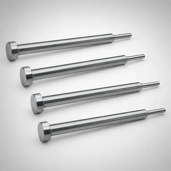
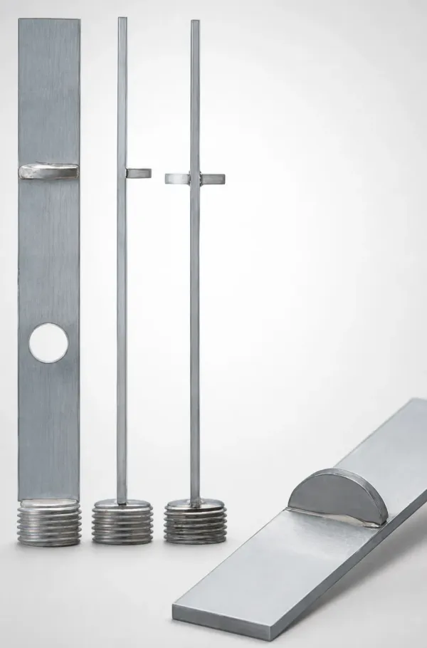
Ejecting a 0.5 g part sounds trivial, until you count the surface area gripping the core. Micro parts cool fast, shrink onto the core details, and offer almost no wall area for a conventional ejector pad. So the mold uses many small pins: ejector pins of 0.3-1.0 mm diameter typical, running in hardened bushings or direct holes at a sliding clearance of 0.005-0.01 mm, roughly half or less of the 0.02-0.05 mm clearance class common in conventional tooling.
That tight clearance is a flash-versus-binding trade. A 0.3 mm pin in a 0.02 mm clearance hole can flash melt past the head on a high-cavity-pressure micro shot, and the flash welds itself to a part that has no trim allowance. At 0.005-0.01 mm clearance the pin still slides after thousands of cycles, but the hole must be precision ground or wire-cut to hold that fit. Small pins also buckle, so the working length of a 0.3 mm pin stays short and the ejector plate is guided so side loads never reach the pin.
Draft is still required, and it is the least negotiable number in the tool. Sub-millimeter features still need 0.5-2 degrees per side typical to release, because the part is shrinking onto the steel and the ejector pins are too small to push hard without marking. Near-zero draft on a deep micro core means the part either sticks, cracks, or comes off with drag marks that no downstream operation removes.
Ejector marks on a sub-mm feature are proportionally huge, which is why mark placement is designed, not discovered. A 0.05 mm witness on a 0.4 mm boss is over 10 percent of the feature. The designer allocates pin locations on hidden or non-functional faces, and where nothing hidden exists, the tool uses blade ejectors in the 0.15-0.3 mm width class, or ejection through core pins for through holes. Every ejector in a micro tool earns its position in the DFM review, because there is no room to move pins after steel is cut.
Venting, Shrinkage and Measurement
Air trapped in a 0.1 mm rib end has nowhere to go, and it burns or blocks the fill. Vent depths for micro features run 0.005-0.015 mm typical, at the shallow end of conventional practice because the shut-offs around a micro cavity are thin and flash easily. Vents go at every flow end: the end of every rib, the far side of every core, the weld line locations, and the dead ends of the runner. Vent lands stay short, typically 0.3-1 mm, and are cleaned by wire EDM or precision grinding so the depth stays accurate.
| Parameter | Micro Range (Typical) | Design Note |
|---|---|---|
| Draft per side | 0.5-2 degrees | Still required on sub-mm features. Near-zero draft sticks or marks the part |
| Vent depth, micro features | 0.005-0.015 mm | Shallow end of conventional practice, resin dependent |
| Vent land length | 0.3-1 mm | Short lands hold depth. Cleaned by wire EDM or grinding |
| Ejector pin diameter | 0.3-1.0 mm | Custom ground below catalog class. Keep working length short |
| Ejector pin sliding clearance | 0.005-0.01 mm | Roughly half or less of the conventional 0.02-0.05 mm class |
| Gate width and land | 0.1-0.5 mm wide, 0.2-0.5 mm land | Smallest cross-section in the system. Freezes last to pack the cavity |
| Shut-off flash budget | 0.01-0.02 mm | Parting-line tolerance class for micro shut-offs |
| Measurement temperature | 20-23 °C | Thermal budget moves steel and parts beyond ±0.005 mm when warm |
← swipe to scroll →
Table: Quick-reference micro tooling values. Figures are typical industry ranges and must be verified against the resin datasheet, cavity geometry, and the mold shop's measured capability before steel is cut.
Shrinkage is where micro molds succeed or fail at trial. Micro part shrink is directional and grade-specific: glass-filled LCP runs roughly 0.1-0.5 percent typical with flow and cross-flow values that differ, while unfilled semicrystalline resins sit near 1.5-2.5 percent. A single cavity scale factor cannot hold ±0.005-0.01 mm on a part made of a resin that shrinks 2 percent, so cavity compensation is built from trial measurements of the actual grade, in the actual cavity geometry, and then applied per feature direction. The first trial is a measurement event, not a sampling event.
Measurement has to see the features before the tolerance means anything. Features of 0.05-0.3 mm sit below the practical reach of most touch CMM styli, so micro parts are measured with optical and vision systems at 20-23 °C, with coordinate measurement on larger datum features and profile projection or vision on the micro details. The gauge itself must resolve to a fraction of the tolerance, roughly one tenth or better, or the measurement noise eats the whole ±0.005-0.01 mm band. Parts are conditioned to room temperature before measurement, because a part measured warm shrinks measurably between the press and the lab.
Compensation changes late in a program are expensive, so micro mold trials are planned as data runs. Short shots map fill balance, cooled parts map shrinkage, and the cavity inserts carry the compensation edits instead of the whole cavity block. That insert strategy keeps one bad shrink assumption from re-cutting the entire tool.
Mold Cost and Cavity Strategy
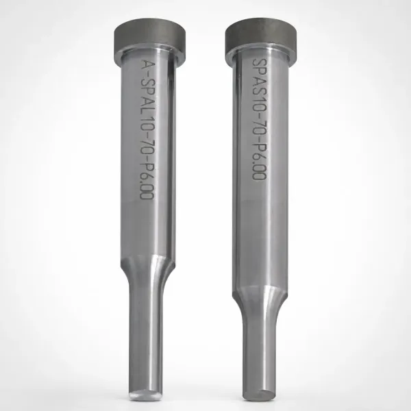
Micro tooling costs 1.5-3 times a conventional tool for the same part complexity, a typical premium that comes from machining hours, not materials. Micro EDM burns slowly, electrodes are made and consumed, polishing is hand work on features that cannot be machine finished, and measurement adds hours per cavity. On the component side, custom ground ejector pins and core pins below 1 mm replace catalog standard parts, and DieStrike's standard ejector pins and core pins ship in 3-7 days while the micro tool itself runs on a 2-5 week injection mold lead time.
Cavity count is the lever that pays for the premium. Sub-gram parts are cheap to mold once the tool runs, so per-part economics push cavity counts up: 4-32 cavities is typical for micro connector tools, rising toward 64 in high-volume automotive connector programs built for OEMs including TE Connectivity, Amphenol, and Luxshare. Connector tooling at that scale follows dedicated rules for terminal pitch, cavity balance, and steel, and it deserves its own design treatment beyond general micro work.
Runner scrap changes the cavity math in both directions. More cavities mean more runner volume per shot relative to part weight, so a 32-cavity cold runner tool can scrap more resin per cycle than it converts into parts. Hot runner systems eliminate that scrap but add nozzle-tip cost and balance risk, and they earn their keep above roughly 8 cavities on micro parts where the runner would otherwise outweigh the product. Below that count, a short, balanced cold runner with slug wells is usually the cheaper tool.
Buy cavity spares inside the first program. A 16-cavity micro tool with one damaged 0.3 mm core pin can stop production while the replacement is ground, so quoting one or two spare cavity inserts and a handful of spare pins at the start costs a fraction of an emergency build. The spare pins ride the standard 3-7 day component pipeline, and the spare cavities de-risk the insert-level compensation edits that trials inevitably require.
DFM Red Flags Before Steel Is Cut
Every expensive micro mold failure was visible on the drawing. Run these checks in the design review, before steel is ordered, and the tool has a chance:
- Ribs or walls thinner than 0.2 mm. A 0.15 mm rib may fill in LCP and fail in every other resin, and it leaves no steel for venting. Confirm the material can actually fill the section before the cavity is cut.
- Blind micro holes without core pins. A 0.2 mm blind hole molded by cavity steel alone traps air, overheats, and breaks pins during ejection. Specify the core pin, its venting, and its support in the drawing.
- Unbalanced runner to tiny cavities. Any path length difference at micro scale becomes a short shot or an overpacked neighbor. The runner must be naturally balanced or the layout must change, because gate-size tuning will not hold across resin lots.
- Gate directly on a cosmetic micro surface. A 0.2 mm gate scar on a 2 mm part is a visible defect. Move the gate, hide it in a feature, or accept the witness before quoting, not after first article.
- Zero or negative draft on deep micro cores. Sub-millimeter features still need 0.5-2 degrees per side typical, and a straight-walled 1 mm deep core will stick, mark, or break the part at ejection.
- Tolerances tighter than the measurement chain. A ±0.005 mm call-out on a feature that the planned gauge cannot resolve to 0.001 mm is unverifiable, and unverifiable tolerances fail audits even when the part is good.
DieStrike runs this exact checklist in its DFM review, with feedback inside 24 hours on the mold design and DFM service. If a feature cannot be machined, vented, ejected, or measured, the report says so with the number that proves it, and the drawing changes while it is still cheap to change.
FAQ: Micro Molding Tooling
Q1. What is the smallest wall thickness a micro mold can actually produce?
Production micro parts typically run walls of 0.1-0.5 mm, with 0.1-0.2 mm walls reserved for high-flow resins like LCP. The limit is set by flow length, gate size, and venting in the mold, not by the machine, so confirm the resin can fill the section before the cavity steel is cut.
Q2. How tight a tolerance can micro molding hold on critical features?
Critical features are commonly held to ±0.005-0.01 mm typical when the mold geometry, shrinkage compensation, and measurement chain are all controlled. The cavity itself is machined to ±0.002-0.005 mm, but the molded part tolerance depends on trial-based shrinkage data and 20-23 °C measurement.
Q3. Why does a micro mold cost 1.5-3 times more than a conventional tool?
The premium comes from micro EDM and micro milling hours, custom electrodes, hand polishing, sub-1 mm ejector and core pins, and per-cavity measurement. Material cost is minor. High cavity counts spread that premium across more parts, which is why micro connector tools run 4-32 cavities.
Q4. Cold runner or hot runner for a micro part?
Cold runners dominate below roughly 8 cavities because the tool is simpler, but the runner can outweigh the parts 5-10 times. Hot runners above 8 cavities cut that scrap at the cost of nozzle-tip expense and balance risk. Cold slug wells are mandatory in either cold-runner layout.
Q5. How do you measure features smaller than 0.1 mm on a micro part?
Optical and vision systems measure sub-0.1 mm features at 20-23 °C, since most touch CMM styli cannot reach them. The gauge resolution must be roughly one tenth of the tolerance or better, and parts are conditioned to room temperature before any measurement that feeds cavity compensation.
The Bottom Line
Micro molding fails on the tooling, not the press. Hold walls, gates, pins, and vents to the numbers above, compensate shrinkage from trial data, and clear the DFM red flags before steel is ordered. DieStrike, an IATF 16949 mold maker, holds micro tooling to ±0.005 mm with 24-hour DFM feedback.
Send the part model for review through the contact page before any steel is cut.
KEEP READING
Related Reading
How to Design for Moldability: 9 Geometry Rules
Draft, wall thickness, ribs, corners and gate geometry for conventional parts. Start here when the part is not yet in the sub-gram micro band.
Read articleArticlePrecision CNC Machining for Mold Components
Tolerance classes from ±0.005 mm to ±0.002 mm, hardened steel machining at 28-52 HRC, and verification by CMM for mold components.
Read articleArticleHard Milling vs EDM for Mold Finishing: How to Choose
Compare corner radius, finish and white layer between hard milling and sinker EDM when you are deciding how to cut a micro cavity.
Read articleServiceMold Design & DFM
DieStrike DFM review flags micro features that cannot be machined, vented, or ejected before steel is ordered, with feedback inside 24 hours.
Read articleNEXT STEP
Ready to Start Your Mold?
Send us your element dimensions or part numbers — our team responds within 24 hours with pricing and lead time.

Written by
Ray ChanMold Buyer's Guide Author · Precision Mold Manufacturing Specialist. Ray helps global importers, distributors and OEMs source factory-direct molds and mold parts.