
How to Design Die Casting Overflows and Weir Vents
Table of Contents
A 4-cavity aluminium housing die passed its first samples and then drifted. At 14,000 shots the overflow wells ran full, the vent lands packed with dross, and X-ray rejects climbed from 3 percent to 17 percent. That is 5,100 castings in 30,000, and the sorting, rework and a held PPAP submission cost the programme six weeks. The root cause sat in the drawing, not the machine: the overflow volume was sized at one-third of the entrained air, and every well shared a direct dump with a cavity vent. This guide gives the sizing, geometry and maintenance numbers that keep overflows and weir vents working for their full insert life.
Overflow and weir vent design starts from one accounting exercise: every cubic centimetre of air and oxide the shot sweeps in has to end up somewhere outside the casting.
The Snapshot
- 15 to 30 percent of every shot lands in overflows and risers. A typical cold-chamber aluminium shot entrains 150 to 250 cm3 of air in the runner and cavity, and that volume has to be displaced into captured steel.
- Overflow volume equals 2 to 4x the air that reaches the last-fill area. Each overflow feeds through a connector sized at 60 to 70 percent of the gate area, placed where the fill pattern closes.
- Well geometry: depth-to-width under 1:2.5, an internal weir wall 1.5 to 3 mm high, 3 to 5 degrees of draft. That combination makes the metal fall instead of flow, so dross stays in the well and the slug releases with the part.
- Vent land 0.15 to 0.3 mm deep for aluminium, 25 to 40 mm long, into a 3 to 5 mm expansion pocket. Build overflow and vent steel as replaceable inserts and budget a regrind every 20,000 to 50,000 shots.
What an Overflow Buys
A cold-chamber machine pushes 2 to 8 kg of molten aluminium through a shot sleeve and an unprimed runner in 40 to 80 milliseconds. The runner and the cavity start that stroke full of air. A typical shot sweeps 150 to 250 cm3 of gas ahead of the metal front, and none of it dissolves into the melt on that timescale.
At the end of the fill that gas is compressed against the last area to close, mixed with oxide film torn from the runner walls. If the metal has nowhere to go, the gas folds into the casting as blow holes, and the oxide becomes inclusions. Porosity found on X-ray is usually traced back to that terminal corner, and the repair ladder is long and expensive. The die casting porosity guide walks that diagnosis after the fact; the overflow is the design step that prevents it.

An overflow is a machined steel pocket placed at the last-fill area, fed through a thin connector. It buys three things at once. It is the terminal destination for gate-entrained air. It is the trap for the first oxide film arriving off the runner, which is the dirtiest metal in the shot. And in the right position it is a local heat sink that delays freeze-off on a thick section.
The cost of that service is real and belongs in the part cost. Captured metal in overflows, risers and the biscuit runs 15 to 30 percent of the total shot on aluminium work. On a 4 kg shot that is 600 g to 1,200 g going to the remelt stream every cycle, at a 5 to 12 percent melt loss between capture and re-melting.
Overflow Volume: The 2 to 4x Air Rule
Size the overflow from the air, not from habit. The starting estimate is the gas volume the fill pattern pushes to the terminal area. A cold-chamber shot sweeps 150 to 250 cm3 of air into the runner and cavity, but the runner and biscuit absorb part of it, and only a fraction reaches the last-fill corner. The rule of thumb that holds on the shop floor: total overflow volume at 2 to 4x the estimated air reaching the last-fill area.
Estimate the entrained air before you cut steel. Take the runner volume plus the cavity volume in cm3; that is roughly the volume of gas displaced. On a housing with a 240 cm3 runner and a 1,400 cm3 cavity, assume the fill carries 200 to 350 cm3 of mixed gas and oxide forward. Size 400 to 1,200 cm3 of total overflow volume across the wells, split over at least two wells per die face.

Count follows the fill pattern, not the cavity count. Every terminal corner flagged by flow analysis gets a well. A die that fills from two gates and closes in four places takes four wells, and the two wells at the far corners carry more volume than the two near the overfill from the second stream meeting. The table below gives the working bands by shot size.
| Shot mass (alloy) | Air swept into runner and cavity | Air reaching last fill | Total overflow volume | Wells | Captured share of shot |
|---|---|---|---|---|---|
| 0.2 to 0.5 kg zinc (hot chamber) | 40 to 80 cm3 | 10 to 20 cm3 | 40 to 80 cm3 | 2 to 4 | 12 to 18 percent |
| 0.5 to 2 kg aluminium | 150 to 250 cm3 | 25 to 60 cm3 | 80 to 200 cm3 | 3 to 6 | 15 to 25 percent |
| 2 to 8 kg aluminium | 300 to 500 cm3 | 60 to 150 cm3 | 200 to 500 cm3 | 4 to 8 | 15 to 25 percent |
| 8 to 20 kg aluminium or magnesium | 500 to 900 cm3 | 150 to 300 cm3 | 500 to 1,200 cm3 | 6 to 12 | 20 to 30 percent |
| Over 20 kg structural | 900 to 1,600 cm3 | 300 to 600 cm3 | 1,200 to 2,400 cm3 | 8 to 16 | 20 to 30 percent |
← swipe to scroll →
Table note: bands are typical working values for unassisted cold-chamber and hot-chamber dies. Recompute the air estimate from your own runner and cavity volumes, then confirm the split against flow analysis before the die is cut.
Two adjustments override the base table. A die with a long thin runner at high gate velocity, say 60 m/s and above, should sit at the top of every band because the turbulence sweeps more oxide. A die running below 350 tonnes with vacuum assist can sit 60 to 80 percent lower, which is covered in the vacuum section.
Overflow Well Geometry: Depth, Weir Wall and Draft
Volume alone does not make an overflow work. The well has to capture dross and refuse to give it back. A deep narrow well does the opposite: the metal front drops down the pocket, splashes, throws oxide off the walls and washes it back toward the connector. The geometry rules below keep the flow calm.
Keep the depth-to-width ratio under 1:2.5. A well holding 60 cm3 wants a footprint around 90 mm by 70 mm and a depth of 25 to 35 mm, not a 30 mm deep slot. The wide shallow plan gives the arriving metal a wall to run up and slow against, and the air layer floats off the surface film toward the vent side of the well.
Put an internal weir wall across the well between the casting and the terminal volume. The crest runs 1.5 to 3 mm below the well roof, so the metal has to fall over it instead of flowing straight along the parting plane. Falling breaks the oxide film's path: dross floats and piles on the upstream face of the weir, while the gas that arrives last escapes under the roof toward the vent pocket behind it.

Draft every wall 3 to 5 degrees and radius the corners at 3 mm minimum. The captured slug has to leave with the part, in one piece, on the trim die. An undrafted well holds the slug until an operator hammers it loose, and each hammer blow costs 0.1 to 0.3 mm of well wall that you can never put back. Corner radii under 3 mm concentrate the shrinkage grip and crack the slug into fragments that pack into the bottom of the well.
Connector Sizing and Last-Fill Placement
The connector is the overflow's throttle, and its area decides when the well starts to receive metal. Size it at 60 to 70 percent of the gate area feeding the same flow path. On a gate of 120 mm2, that gives a connector of 72 to 84 mm2, commonly a 6 mm wide by 12 mm long tab 1.2 to 1.5 mm thick cut into the parting line.
The logic is sequence, not flow. At 60 to 70 percent of gate area the connector freezes slower than the casting closes but faster than the main runner, so the well stays open through the last 10 to 20 percent of fill. A connector sized at full gate area fills the well beside the casting and wastes 30 to 50 percent of its volume pushing clean metal through a trap that did not need it. A connector under 50 percent chokes early and the air reaches the casting.
Place every overflow at the last area to fill, taken from the flow report and confirmed on the T1 fill pattern. The classic error is a symmetric die with wells on the corners the designer liked rather than the corners the metal closed on. If the fill analysis flags two meeting streams 80 mm from the gate, the well belongs at the weld line, or the oxide from that impingement stays in the part.

Keep connectors short, under 40 mm, and never route one back toward the gate. A long connector adds 4 to 8 cm3 of dead volume that must fill before the well does, and it arrives hot enough to remelt the dross it carries. Where the geometry forces a long path, sink a small catcher well of 10 to 15 cm3 halfway and make the terminal well do only the gas work.
The gating that feeds these wells is designed in its own right, and the gate and runner design guide covers gate velocity, runner shrinkage and the fill patterns the overflow system finishes. Design the two together: an overflow plan bolted onto a badly sequenced runner captures air at the wrong corners and buys nothing.
Overflow as a Heat Sink
A well full of steel is a thermal device before it is a trash can. Aluminium die steel conducts 25 to 33 W/m K, molten aluminium sits at 640 to 690 °C, and the die face runs 180 to 260 °C. A 20 mm thick steel pad sitting ahead of an 8 mm boss holds heat that a 2 mm wall cannot, and it delays freeze-off on the thick section by 2 to 5 seconds on a 60 to 90 second cycle.
Use that deliberately on shrinkage hot spots, not on gas hot spots. The conflict is real: a well placed to feed a thick section with liquid metal may sit nowhere near the last-fill corner, so the same volume does thermal work but no venting work. Solve it with two features. Put the venting wells at the terminal corners at full volume. Put a smaller thermal riser, 30 to 60 percent of a venting well, directly on the thick section with a fat connector at 90 to 100 percent of gate area so it stays liquid longest.
Map the wells against the alloy freezing range before you commit the layout. A380 freezes across roughly 520 to 590 °C, so the mushy zone holds the slug to the well wall for several seconds and the connector tears rather than shears. MAG and AZ91 magnesium, freezing near 460 to 630 °C with a shorter mushy range, release cleaner and tolerate a thinner connector. Ask the foundry for the actual freezing range of the alloy grade they will pour, then set the connector thickness at the low end for wide-range alloys.
Interlock the wells with the cooling circuits. A die-casting die carries water or oil circuits at 12 to 20 mm from the cavity face, and the overflow block is the natural place to hang a baffle or an impulse line. Put a cooling circuit under the thermal riser when the boss still shows sink at T1, and pull it back 10 mm when the well freezes the slug too early to capture gas. Each move is a 5 to 15 second change in the local freeze time and costs nothing but a drill pattern on the die card.
The same logic applies to the sprue and biscuit, which behave as a giant overflow holding 15 to 25 mm of heat mass behind the gate. Keep the biscuit inside the shot-sleeve diameter, and never let it double as a vent path.
Weir Vent Land Depth and Length by Alloy
A weir vent is a shallow machined groove in the parting line that lets gas escape while the metal freezes solid in the channel. The physics is a race between two solidification fronts. Gas moves through the land at 1 to 3 m/s with no resistance. Metal enters the same groove, loses heat to both steel faces, and bridges the channel in a fraction of a second. Get the depth right and gas leaves while metal stops.
Land depth is alloy-specific because oxide formation and fluidity differ. Aluminium takes 0.15 to 0.3 mm. Zinc tolerates 0.10 to 0.20 mm because it freezes fast and stays clean. Magnesium needs 0.20 to 0.35 mm; its oxide is tenacious and a shallow land plugs within a few hundred shots. Depth beyond those bands becomes flash: at 0.4 mm an aluminium land produces a fin that survives trim and reaches the customer.
| Alloy | Vent land depth | Land length | Expansion pocket | Relief channel | Cleaning interval |
|---|---|---|---|---|---|
| Al-Si (A380, A383) | 0.15 to 0.3 mm | 25 to 40 mm | 3 to 5 mm deep | 6 to 10 mm wide | Every 2,000 to 5,000 shots |
| Zn-Al (ZAMAK 3, 5) | 0.10 to 0.20 mm | 20 to 35 mm | 3 mm deep | 5 to 8 mm wide | Every 5,000 to 10,000 shots |
| Mg (AZ91D) | 0.20 to 0.35 mm | 25 to 40 mm | 4 to 5 mm deep | 8 to 12 mm wide | Every 1,000 to 3,000 shots |
| Cu (red brass, low fume) | 0.20 to 0.30 mm | 30 to 45 mm | 4 mm deep | 8 to 10 mm wide | Every 1,500 to 3,000 shots |
← swipe to scroll →
Table note: depths are measured with a 0.05 mm feeler on a clean land at trial, not from the drawing dimension after washout. Set the cleaning interval from the first plugged vent observed on your own alloy and release agent.
Run the land 25 to 40 mm long, then dump into an expansion pocket 3 to 5 mm deep. Without the pocket the land chokes: oxide plates settle on the land floor and seal it from the outside in. The pocket gives the gas a place to expand and a visible surface to show the deposit. From the pocket, a relief channel 6 to 10 mm wide carries the gas to the die edge or to a vent post drill of 4 to 6 mm.
Position vents on the same last-fill logic as overflows, plus two more spots: over cores and behind ejector pins where the metal closes last. Place a land on both sides of a long core pin, because the pin acts as a dam and traps gas on its downstream face. Total vent land area should exceed the gate area by 2 to 3x, so the die never has less escape path than inflow.
Never cut a vent into a slide or a lifter face that carries the dimension. Vent steel washes and the land depth opens up; a washed vent on a shut-off becomes a 0.3 mm fin on a mating surface. Vents belong on the main blocks or on dedicated replaceable inserts.
Vent and Overflow Interaction: the Bleed Stack
The rule that prevents most overflow rework: a vent must never dump directly into an overflow well that the machining department later has to clean or weld. Dross packed into a well by a vent stream is exactly the material you designed the well to capture, and routing vent gas through it pressurises the trap.
The correct bleed stack reads, from the casting outward: casting edge, weir vent land, expansion pocket, then the well's own terminal volume, and only then the relief channel to atmosphere. The vent and the overflow share the pocket but not the well floor. Metal that flashes into the vent land freezes in 0.15 to 0.3 mm and stops; gas continues under the well roof and out the relief.
Keep a 3 to 5 mm land of steel between a vent groove and an overflow connector. Without it the two features short-circuit and the well becomes a vent, which means the slug cools too fast to capture oxide and the gas escapes with the scrap metal instead of ahead of it. That is the failure mode that shows up as porosity clustered along the last-fill corner even though the wells are full.
On multi-cavity dies, give every cavity its own bleed stack and never manifold two cavities into one relief channel. A cavity that fills 0.5 seconds ahead of its neighbour pushes gas back through the shared channel into the slower one. Shared reliefs are a common cause of a one-cavity porosity problem that refuses to move with process changes.
Where a well must be rebuilt by welding, cut the relief channel so the packed dross can be blown out with air at 0.4 to 0.6 MPa before the die goes to repair. A well that cannot be cleaned cannot be welded soundly, and porosity returns within 500 shots of the repair.
Replaceable Inserts and the Washout Budget
Overflow and vent steel dies first. Molten aluminium at 660 °C arriving at 40 to 80 m/s erodes the connector edges, and the flux and oxide chemistry eats the land floor. On a production aluminium die, vent lands open by 0.05 to 0.15 mm every 20,000 to 50,000 shots, and the well walls lose 0.2 to 0.5 mm per 100,000 shots. That is not a defect; it is the wear budget you design around.
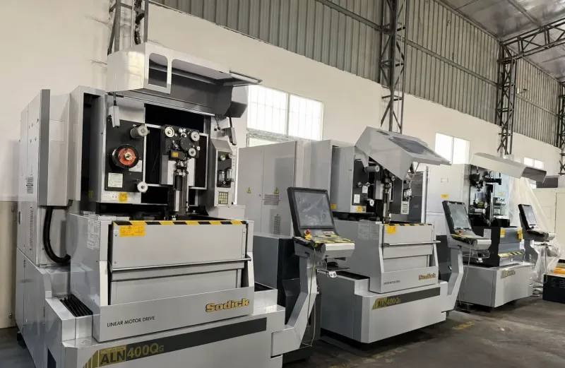
Build both features as replaceable inserts, not as cuts in the cavity block. Each insert carries 2 to 4 mm of steel margin around the well and the land, so a regrind removes worn material and restores the original geometry. In our shop we hold insert profiles to ±0.005 mm on the mold line, and to ±0.002 mm where the EDM and jig-grinding operations cut the weir wall, so a regrind set stays interchangeable across cavities.
Budget the cycle: a regrind or insert swap every 20,000 to 50,000 shots on aluminium, every 50,000 to 80,000 on zinc. Make 3 to 5 spare inserts per die at build time; standard components ship in 3 to 7 days and insert steel is cut to the same schedule. A die that waits four weeks for one vent insert costs more downtime than the whole spare set.
Record two failure signatures by location, not as a single die-level number. Washout onset is the shot count where a land measures 0.05 mm deeper than drawing; solding onset is where aluminium first keys into the steel. Track both per insert on the die card. Soldering and washout feed each other, and the die soldering guide covers the coating and spray choices that slow both. When solding appears first at one well and washout at another, the fill pattern is uneven and the fix is a connector resize, not a bigger insert.
Coat the working faces. H13 at HRC 44 to 52 survives the thermal cycling, but the vent lands and connector edges gain 2 to 3x life from a 0.02 to 0.05 mm hard chrome or a 2 to 5 µm PVD layer that resists aluminium wetting. Re-coat at the insert swap, never on the assembled die, because a plating build-up changes land depth and flash follows.
Vacuum Versus Overflow: the Decision Framework
Vacuum assist changes the arithmetic. An airtight cover around the shot, pulling the sleeve and cavity down to 1 to 5 mbar within 150 to 300 ms before the plunger moves, removes most of the gas the overflow was built to capture. Well count and volume can drop 60 to 80 percent, and the surviving wells handle oxide rather than air.
Three numbers decide whether the trade is worth it. First, the part: a structural bracket with no pressure test or weld zone rarely earns the vacuum cost, while a housing that must hold 20 bar after machining usually does. Second, the alloy: magnesium's oxide load keeps a meaningful well volume even under full vacuum. Third, the cell: vacuum needs seal surfaces checked every shift and a cycle window disciplined to ±0.5 seconds, and a three-shift line that skips the seal check loses the benefit inside a week.
The tooling penalty is concrete. A vacuum-ready die adds the cover frame, the seal lands and the evacuation porting, and the design work goes up because every vent path now competes with the vacuum loop. The vacuum die casting design guide covers that architecture end to end. EV battery housings and busbars on the ev-energy line almost always run the hybrid: reduced wells for oxide, vacuum for air. If the programme is a zinc hot-chamber clip at 2,000,000 shots a year, keep the full overflow set and skip the pump.
Trial Verification of the Overflow System
Verify the overflow plan on the die before you sign the porosity spec. Four checks, all measurable, all done in the first 50 shots of the T1 run. They belong in the trial report alongside the dimensional data, and we build them into the die casting mold sampling at IATF 16949.
Weigh the captured metal. Trim the runner, biscuit and all slug volumes off 10 consecutive castings and weigh them. The captured share should sit inside the design band of 15 to 30 percent of the shot. Under 12 percent means the wells did not fill, so the gas went into the parts. Over 35 percent means the connectors are too fat and you are paying remelt cost on clean metal every cycle.
Cut the wells open. Section two wells per die on the first shift and photograph the interior. A working well shows dross layered against the upstream weir face and a clean slug on the terminal side. A slug that is uniformly bright means the metal flowed instead of fell, and the weir crest needs to drop 1 mm. A well floor packed with dark residue means the vent dumped into it, and the bleed stack needs separating.
Gauge the vent lands. Measure each land depth with a 0.05 mm feeler set at the trial, record the value per insert, and re-measure at 10,000 shot intervals. A land that opens 0.05 mm in 10,000 shots is washing at 10x the expected rate and the insert steel or coating needs changing before production starts.
X-ray the last-fill corners. Aim the beam at the 80 mm around every well connector, because that is where the design says the gas was captured. Porosity clustered beside a well that reads full is the signature of a vent short-circuit, fixed by moving steel, not by changing the machine. Then run the confirmation over 30 to 50 consecutive shots with the pattern stable before the die card numbers get locked.
Overflows and Weir Vents FAQ
Q1. How much overflow volume does a die casting die need?
Total well volume at 2 to 4x the air the fill pattern drives to the last-fill area, which lands at 80 to 2,400 cm3 across the shot sizes in the sizing table. Size from the runner plus cavity volume of your own die, then trim 60 to 80 percent off the total if the cell runs vacuum assist.
Q2. Why does my overflow have a weir wall in it?
To break the flow path. The crest sits 1.5 to 3 mm below the well roof so metal must fall over it instead of streaming along the parting plane. Falling stops the oxide film where it is, while gas continues under the roof to the vent. Without the weir, the first dross in the well washes straight back toward the connector on the next shot.
Q3. How deep should die casting vents be?
0.15 to 0.3 mm for aluminium, 0.10 to 0.20 mm for zinc, 0.20 to 0.35 mm for magnesium, over a land 25 to 40 mm long into a 3 to 5 mm expansion pocket. Deeper lands flash; shallower ones plug with oxide in 1,000 to 5,000 shots depending on alloy.
Q4. Can a vent discharge directly into an overflow well?
No. Vent gas that blows through the well floor packs dross into the trap and pressurises it, and the porosity comes back beside the well even though it reads full. Keep 3 to 5 mm of steel between the vent groove and the connector, and let the two features share only the expansion pocket.
Q5. How often do overflow and vent inserts need replacing?
Regrind or swap every 20,000 to 50,000 shots on aluminium and every 50,000 to 80,000 on zinc, with 3 to 5 spare inserts cut at build time. Track washout onset and solding onset per insert location on the die card so the interval comes from your own data, not a handbook number.
The Bottom Line
Overflows and weir vents are one air-handling system drawn twice. A cold-chamber shot entrains 150 to 250 cm3 of air, the wells take 2 to 4x whatever reaches the last-fill corner through connectors at 60 to 70 percent of gate area, and the weir wall at 1.5 to 3 mm plus a depth-to-width ratio under 1:2.5 is what keeps the captured dross from walking back into the casting. The vent land finishes the job at 0.15 to 0.3 mm for aluminium over 25 to 40 mm into a 3 to 5 mm pocket, and the bleed stack keeps the two features from short-circuiting each other.
The economics close the loop. Captured metal costs 15 to 30 percent of every shot to the remelt stream, so undersized wells trade that money for X-ray rejects, and oversized wells burn alloy that never had to move. Build the steel as replaceable inserts on 2 to 4 mm margins, regrind on a 20,000 to 50,000 shot budget, and log washout and solding onset per location so the next die starts from measured numbers instead of folklore. A vacuum loop can retire 60 to 80 percent of the well volume when the part justifies the cycle discipline. Hold these numbers and the porosity problem never reaches the inspection table.
KEEP READING
Related Reading
Die Casting Mold Manufacturing
IATF 16949 die building with overflow and vent insert design, 2 to 5 week lead times and +/-0.005 mm mold accuracy.
Read articleArticleHow to Prevent Die Soldering in Die Casting
Why overflow and vent steel washes out first and what solding onset tells you about the die.
Read articleIndustryEV and Energy Industries
Structural housings, busbars and battery parts where overflow and vacuum strategy decides the porosity class.
Read articleArticleHot Chamber vs Cold Chamber Die Casting
Shot speed, air entrainment and gate geometry differences that change how much overflow a die needs.
Read articleNEXT STEP
Ready to Start Your Mold?
Send us your element dimensions or part numbers — our team responds within 24 hours with pricing and lead time.

Written by
Ray ChanMold Buyer's Guide Author · Precision Mold Manufacturing Specialist. Ray helps global importers, distributors and OEMs source factory-direct molds and mold parts.