
How to Reduce Die Casting Porosity: Gas, Shrinkage and X-ray
Table of Contents
A 2 kg A380 housing rejected at X-ray carries 4 to 7 USD of metal, machine time and finishing straight to the scrap bin. At a 15 percent reject rate that is roughly 15,000 USD lost per 20,000 shots, and a containment audit stalls PPAP sign-off for weeks. Porosity is not one defect. It is three families with different origins and opposite fixes.
Every number that decides the outcome sits between the sleeve and the die surface.
The Snapshot
- Gas porosity is round and shiny. Smooth bubbles cluster under the skin near gates and overflows. Between 60 and 80 percent of entrained air arrives in the slow-to-fast transition.
- Shrinkage porosity is jagged and predictable. Irregular dendritic cavities sit at the last-to-freeze hot spot in the thickest section. No vent removes them.
- Acceptance is numeric. CT porosity under 0.5 percent by volume for structural parts, under 2 percent for pressure-tight parts with 0.5 mm wall penetration allowed.
- The first fixes are settings. Sleeve fill 30 to 50 percent, fast shot 4 to 8 m/s, vacuum 20 to 50 mbar, intensification 40 to 120 MPa within 0.5 seconds of fill.
Gas Porosity vs Shrinkage Porosity
Misdiagnosis is the most expensive mistake in porosity work because the two families respond to opposite corrections. Gas porosity is air physically trapped by the advancing melt front. Shrinkage porosity is metal that was never fed into the space the casting gave up as it solidified.
On a sectioned, polished and etched surface the difference is visible at 10x magnification. Gas pores are round, smooth and shiny, because the cavity was an air bubble frozen in place by solidifying metal. They cluster in predictable addresses: under the skin, near the gate, and downstream of overflows where turbulent flow dumped its cargo.

Shrinkage porosity looks nothing like this. The cavities are irregular, jagged and dendritic, a sponge of feeding channels between solid arms. They sit at the last location to freeze, the thermal center of the thickest section, and they are always there rather than scattered. A boss, rib intersection or corner at 1.5 to 2 times nominal wall is the shrinkage address.
Three field tests separate the families in one hour. Location first: voids at the hot spot of a thick section are shrinkage even if one or two look round. Shape next: over 100 measured pores, mostly round and smooth points to gas, while ragged dendritic arms point to shrinkage. Response last: raising intensification pressure compresses shrinkage voids but leaves a gas bubble in place, now merely smaller.
The remedy split follows the diagnosis. Gas is cured on the machine through sleeve fill, shot profile, venting and vacuum. Shrinkage is cured in the die through hot spot cooling, gate size and intensification timed before gate freeze. A program that treats both with the same lever fixes neither and burns two trial rounds.
Hydrogen Porosity and Micro Pinholes
A third family appears when the section looks clean on the bench but the part weeps on the leak test. Hydrogen porosity forms fields of micro pinholes, typically 0.1 to 0.5 mm across, distributed through the full wall rather than clustered under the skin.
The mechanism is solubility. Molten aluminium dissolves roughly 20 times more hydrogen than the solid metal can retain. As dendrite arms close, the surplus comes out of solution and nucleates thousands of tiny bubbles along the last-fed regions. Hydrogen arrives from moisture in the charge, damp scrap, wet crucibles and unpreheated tools. A damp charging bucket is enough to move the reading.
Two plant habits create it at scale. Holding melt above 730 C for hours drives gas pickup. Skimming dross back into the bath re-releases its gas load every heat, because pour-hole dross can carry 40 to 70 percent entrained metal. The fix is melt hygiene. Dry the charge, rotary degas to below 0.15 mL of hydrogen per 100 g of melt, and never re-melt dross. On the tooling side, keeping the die above the dew point through warm-up stops condensation from entering the cavity.
Measuring and Accepting Porosity
Reduction programs need a number, and die casting has three accepted ones. Sectioning is the oldest. The part is cut through the defect zone, polished, etched and measured. A common shop rule rejects a casting when voids cover more than 2 percent of the section area on a critical plane. Automotive structural programs often hold 1 percent or less. Sectioning destroys the part but shows pore shape, so it remains the diagnosis of record.
X-ray is the production screen. Castings are graded against ASTM E505 reference radiographs, whose levels 1 to 3 define allowed void size and population across the field. A typical automotive drawing calls level 1 to 2 in the section under inspection. X-ray sees gas porosity well and shrinkage less well, because jagged feeding voids give low density contrast against sound dendritic metal.

Computed tomography is the acceptance instrument for leak-tight and safety-critical parts. CT measures porosity as a volume fraction and maps every void against the wall, so a drawing can state depth limits instead of area rules.
| Part class | Method | Acceptance number | What it prevents |
|---|---|---|---|
| Structural housing | CT volume fraction | Under 0.5 percent total porosity | Fatigue and pull-out failure on load paths |
| Pressure-tight part | CT with wall mapping | Under 2 percent, wall penetration 0.5 mm max | Interconnected void paths that weep fluid |
| Leak-tested part | CT plus decay test | Porosity depth under 15 percent of wall | Surface-connected pinhole leaks |
| General screen | X-ray vs ASTM E505 | Level 1 to 3 per drawing | Escapes of large single gas bubbles |
| Bench diagnosis | Section and etch | 2 percent void area reject line | The wrong family being blamed |
← swipe to scroll →
Table note: thresholds are typical industry and automotive values. Confirm the class, level and sampling plan against the customer drawing and the PPAP submission before trial tooling is cut.
The Air Budget of One Shot
Before chasing settings, count where the air actually comes from. On a cold chamber aluminium shot, 60 to 80 percent of entrained gas arrives during the slow-to-fast transition. That is when the plunger accelerates and the melt front goes turbulent at maximum velocity change. Another 10 to 20 percent is drawn inside the sleeve before that moment, over the biscuit face and past a leaking plunger tip. The remainder comes from spray, lube and gas released by the die surface itself.
That budget sets the priority order. A vent cannot fix transition turbulence, because the gas is already folded through the melt rather than sitting ahead of the front. A bigger vent only evacuates gas that still has a path to atmosphere at end of fill. Programs that start by enlarging vents and end by moving the acceleration point have worked the problem in the wrong order.
The transition is controllable on any modern machine. Move the switchover to 20 to 40 mm of plunger travel before the gate. Run the slow phase at 0.1 to 0.3 m/s until the melt has passed the pour hole, then accelerate in the last third of the sleeve where the biscuit seals the path. Shot-position logging at 1 mm resolution makes the change measurable across 100 shots instead of one lucky trial.

Turbulence has a velocity ceiling, not a preference. Gate fill velocity above roughly 40 to 60 m/s in aluminium folds the front on itself. Cavity flow above 4 to 8 m/s does the same, and the X-ray picture stops improving no matter what the vacuum does afterwards. Gate velocity is a tooling variable first: runner and gate geometry decide whether machine settings can ever be honest.
Sleeve Fill, Plunger Tip and Shot Profile
Sleeve fill ratio is the cheapest porosity control on the cell. Keep the shot at 30 to 50 percent of sleeve volume. Below 25 percent the melt never covers the pour hole cleanly, the biscuit rolls air forward and the casting grows a gas band under the top skin. Above 70 percent the compression cushion disappears, the plunger hits hydraulic hammer and the intensification wave arrives distorted.
Sleeve and tip wear together, and the wear shows up as porosity two steps later. Cold chamber biscuits run 45 to 70 mm in diameter with the plunger tip carrying 0.05 to 0.15 mm diametral clearance. A worn tip leaks molten metal past its face; the leak oxidizes into black bands and dark stringers that CT reads as elongated porosity. A scored bore lets the biscuit slip instead of push and produces 1 to 3 percent fill weight drift. The usual wear band runs 0.1 to 0.3 mm deep on the pour-hole side, and it repositions the shrinkage void shot by shot.
Measure the sleeve bore at three heights every 5,000 shots and reject at 0.4 mm oversize. Log biscuit weight every 50 shots; a moving average that wanders more than 2 percent is a feeding alarm before it is ever an X-ray alarm.
Runner, Gate and Overflow Design
The feed system decides how much air reaches the cavity after the shot profile has done its worst. Keep runner length below a 25:1 ratio to its cross-section dimension; longer runners multiply friction, force higher gate velocity and dump the turbulence budget into the casting. Runner sections stay full and radiused, with no sudden area change wider than 20 percent between stages.
A well-designed gate lets the melt front settle and enter the cavity laminar, which is what makes vacuum and intensification worth anything at all. The geometry rules sit in the gates and runners design guide. For porosity, three numbers matter. Gate velocity is capped by alloy. Gate thickness stays above 1 mm so the gate does not freeze before intensification arrives. Gate position aims at the heaviest nearby section so the runner stays a feeding reservoir.

Overflows are deliberate air traps. Place them at the last-fill zone the simulation predicts and size total overflow volume to capture 5 to 15 percent of shot weight. Each overflow carries a vent of 0.1 to 0.2 mm depth and 3 to 6 mm width on aluminium. Hold the vent to a land of 3 to 5 mm before the relief channel. Deeper vents flash; a short land sprays metal into the relief. An overflow that is never skimmed stops being a trap and becomes a cold slug.
Vacuum Assist and Valve Gating
Vacuum removes the air that tooling geometry cannot. High-vacuum die casting pulls cavity and sleeve pressure to 20 to 50 mbar absolute before the shot, collapsing the gas phase that would otherwise be folded into the casting. On a well-sealed die the measured effect is a porosity volume fraction falling from the 2 to 4 percent range toward under 0.5 percent. The part can then be heat treated and welded, because trapped gas no longer blisters at solution temperature.
Vacuum only pays if the die seals. Parting-line seals, slide seals and the sleeve seal ring must hold 30 mbar through the full shot. A 0.1 mm leak path is enough to keep the pump chasing atmosphere instead of evacuating gas. The seal, sensor and pump package is designed in the vacuum-assisted die casting guide. The porosity rule is blunt: read the vacuum log before blaming the shot curve, because a die reaching 300 mbar instead of 30 mbar behaves like no vacuum at all.

Valve gating attacks the same problem upstream. A driven pin opens and closes each runner channel on command, so cavities fill in sequence rather than simultaneously. The last cavity then closes against its own overflow instead of a sprue full of folded oxide. On multi-cavity tools a staged valve sequence routinely halves gas-porosity rejects without touching sleeve fill.
Intensification Pressure and Gate Freeze
Shrinkage is a feeding problem, and feeding has a clock. Intensification, or squeeze, pressure of 40 to 120 MPa must reach the biscuit within 0.1 to 0.5 seconds after fill completes. Apply it later and the gate has frozen, the pressure dies in the runner and the hot spot solidifies unsupported. The window is set by gate solidification: a 6 mm gate on A380 freezes in roughly 3 to 8 seconds depending on die temperature and local cooling.
That window decides three design values at once. Gate thickness must freeze after, not before, the connected section finishes solidifying. The biscuit must keep enough volume to compress, which is why a lost cushion above 70 percent sleeve fill converts directly into shrinkage voids. And intensification delay must be tuned inside the same 0.5 second band as the switchover point, with pressure ramps logged in milliseconds rather than inherited from a previous program's trial sheet.
Two signatures confirm the feeding story rather than the air story. Void clusters sit dead-center of the last-to-freeze section, and they smear into tight cavities instead of vanishing when squeeze pressure rises. If 20 MPa more moves the pattern measurably, the fix is freeze timing and local cooling. If nothing moves, go back to the air budget.
Die Thermal Balance and Hot Spot Cooling
A die casting die is a heat exchanger, and where it under-cools, shrinkage forms. Hold the working die at 180 to 250 C with no more than 15 C spread across the production band. Measure at 5 or more points with a contact pyrometer after 30 to 50 steady-state shots. A cold die at start-up freezes the front early and hides shrinkage until the die warms 40 C later in the shift. First-article reports taken on a cold tool therefore mislead.
The thermal fix set is standard. Blow localised cooling onto the hot spot with a dedicated circuit or jet line. Set a beryllium-copper insert within 10 to 15 mm of the thick section to pull heat faster than steel can. Add blind-cooled pegs in the core where a boss or rib intersection runs last to freeze. Each move steers the solidification front back toward the gate so the runner can feed it.
The circuit layout and gradient numbers are worked out in the die casting die cooling design guide.
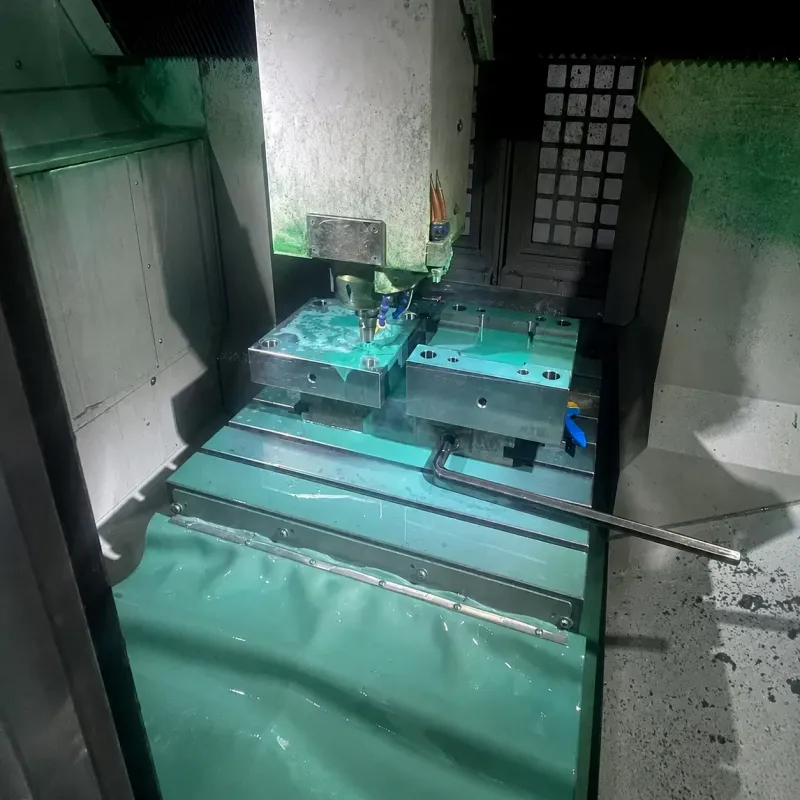
Overcooling has its own signature and it is easy to misread. A circuit that skims too much heat freezes the gate early and starves the cavity, so voids stay at the hot spot even though the nearby thermocouple reads beautifully. Verify balance against fill and solidification simulation before drilling a new line into a production die. A drilled circuit cannot be un-drilled, and 20 minutes of local spray tuning costs far less than a two-week insert rebuild.
Die Condition: Soldering, Wear and Venting
A die that ran clean at 20,000 shots is not the die you are running at 60,000. Three wear mechanisms rebuild the porosity rate while every machine setting stays frozen on the approved trial sheet.
Soldering comes first: aluminium welds to bare steel when the surface runs dry or drops below roughly 150 C, and each welded patch tears out steel on the next ejection. The exposed, oxidized surface then nucleates gas and drags melt along the wall longer than designed. The control is the spray program, so apply a thin even film of water-based lubricant at the supplier dilution band rather than a flood. A flooded die chills back toward the soldering threshold and overcools the hot spot at the same time. Film targets and nozzle layout are set in the die spray and release agent guide.
Vent blinding comes second. Spray residue, lube carbon and injected oxide seal a 0.15 mm vent within shifts. A blocked overflow stops trapping gas and becomes a cold slug that shortens the feeding path behind it. Clean vents and skim overflows every shift on aluminium and every 2,000 to 5,000 shots at critical last-fill points, verified with a feeler. The interval belongs in the die casting maintenance plan, next to heat-check inspection, because 0.2 mm cracks on a checked surface also release trapped gas into every shot.
Wear comes third. Erosion at the gate, core lead edges and the biscuit entry widens runner and gate dimensions by 0.2 to 0.5 mm over 50,000 to 100,000 shots. Fill balance shifts and the last-fill zone drifts away from the overflows built to catch it. Measure gate dimensions at trial, at 50,000 shots and after every weld repair.
The Porosity Decision Tree
The fastest route from a failed X-ray to a fixed process is one sectioning cycle with the fill simulation open beside it. Pore shape names the family, pore location names the mechanism, and the mechanism names the setting or the steel change.
- Round and shiny, under the skin near gate or overflow. Entrained air. Check sleeve fill against the 30 to 50 percent band, then the switchover position, then plunger tip leakage. If the die carries vacuum, log achieved pressure against the 20 to 50 mbar target first.
- Round, scattered wall to wall through the section. Melt-borne gas. Review hydrogen content, dross handling and charge dryness before blaming the machine.
- Jagged and dendritic, dead-center of the thickest section. Shrinkage. Check 40 to 120 MPa intensification arriving within 0.5 seconds, then gate freeze against the 3 to 8 second window, then local cooling.
- Jagged, along a rib-to-wall junction away from the thermal center. The feeding path froze early. Move the gate or thicken it so the runner stays liquid past the section's solidification.
- Micro pinholes through the wall on a part that passes film. Hydrogen. Flux, degas and dry the charge, and confirm below 0.15 mL per 100 g.
Hot-work grades such as H13 and 1.2344 hold their behavior through the 180 to 250 C band only when heat treatment and preheat discipline hold. A die run cold at every shift start accumulates heat checking and porosity together. Grade choice for that duty is covered in the H13 versus H11 versus 1.2367 hot-work steel comparison.
Die Casting Porosity FAQ
Q1. Can intensification pressure squeeze gas porosity out of a casting?
No, it compresses it. A bubble at atmospheric pressure shrinks by roughly 30 to 80 percent under 40 to 120 MPa, and the compressed void still counts on CT. Intensification cures shrinkage; sleeve fill, the transition move and venting cure gas.
Q2. What sleeve fill ratio prevents porosity on a cold chamber machine?
Hold 30 to 50 percent of sleeve volume. Below 25 percent the melt drags air over the pour hole; above 70 percent the cushion disappears and hydraulic hammer distorts the shot. A biscuit-weight average drifting 2 percent is a wear alarm.
Q3. Does vacuum die casting fix shrinkage?
It fixes gas. High vacuum at 20 to 50 mbar removes the air around the melt front, which is why structural vacuum parts routinely land under 0.5 percent porosity by volume. Shrinkage voids have no gas phase to evacuate, so they still need gate freeze timing, intensification and local cooling.
Q4. How tight should X-ray acceptance be written?
Per drawing and part class. A general screen grades against ASTM E505 reference radiographs at levels 1 to 3. Structural automotive parts typically call level 1 to 2 in the critical view, and leak-tight or heat-treat parts increasingly specify CT volume fractions instead of film levels.
Q5. Why did porosity appear on a die that ran clean for two months?
Check the die, not the settings. Blinded vents and overflows, a plunger tip past 0.15 mm clearance, a sleeve bore 0.4 mm oversize or 0.2 mm gate erosion all rebuild the defect rate with the process sheet untouched.
The Bottom Line
Die casting porosity reduces to three diagnosis questions and one set of numbers. Are the voids round or jagged? Are they at the gate side or the thermal center? Does the part need a film level, an area rule or a volume fraction? Hold these bands:
Sleeve fill runs 30 to 50 percent and cavity flow 4 to 8 m/s. The transition sits 20 to 40 mm before the gate, and overflows capture 5 to 15 percent of shot weight at the last-fill zone. Vacuum holds 20 to 50 mbar, intensification delivers 40 to 120 MPa inside 0.5 seconds of fill, and a 6 mm A380 gate freezes in 3 to 8 seconds. The die face stays at 180 to 250 C within 15 C across the band.
Gas answers to the shot profile and the seals. Shrinkage answers to the feeding clock and the cooling map. Hydrogen answers to the melt shop. Measured against the same CT or section every time, the fix becomes arithmetic rather than opinion. A program that runs one sectioning cycle per iteration closes in two rounds instead of twenty.
DieStrike builds die casting dies and precision tooling to IATF 16949 with +/-0.005 mm mold accuracy. EDM and jig-grinding work holds +/-0.002 mm, tool steel is hardened to HRC 62, and the plant runs 120+ machines with tool lead times of 2 to 5 weeks. Gate, overflow, vent and cooling layouts for porosity-critical parts are DFM-reviewed against your fill simulation before the first cut, so the X-ray screen sees a die designed to pass it.
KEEP READING
Related Reading
Hot Chamber vs Cold Chamber Die Casting
Why the machine choice sets the air entrainment baseline before the die is even cut.
Read articleArticleHow to Extend Die Casting Mold Life
Steel, coating and spray discipline that keep vents, lands and thermal control honest.
Read articleServiceDie Casting Mold Manufacturing
IATF 16949 die casting dies with +/-0.005 mm accuracy, thermal balance design and 2 to 5 week lead times.
Read articleArticleInjection Mold vs Die Casting Mold
Where a plastic defect list stops applying and metal porosity rules begin.
Read articleNEXT STEP
Ready to Start Your Mold?
Send us your element dimensions or part numbers — our team responds within 24 hours with pricing and lead time.

Written by
Ray ChanMold Buyer's Guide Author · Precision Mold Manufacturing Specialist. Ray helps global importers, distributors and OEMs source factory-direct molds and mold parts.