
How to Extend Die Casting Mold Life
Table of Contents
A die casting die that fails at 40,000 shots instead of 120,000 does not just cost a replacement die. It costs the downtime, the rework of 80,000 castings that may carry micro-cracks, and the customer program that moves to another supplier. Aluminum die casting dies typically run 50,000 to 150,000 shots before major repair (published range) — and the spread between the low end and the high end is almost entirely decisions made before the die is ever mounted.
Dies do not die of old age. They die of four specific wear mechanisms: heat checking, soldering, erosion, and washout. Each one has a root cause in steel grade, heat treatment, cooling design, or maintenance — and each one is preventable or delayable with the right tooling decisions. This guide covers the whole chain: which steel to specify, how to balance hardness against toughness, how to design the cooling so the die surface sees a controlled thermal cycle, and what to check at the 10,000-shot mark before the cracks get deep enough to scrap the die.
Everything here is about the die itself — the tooling that makes the casting. If you are comparing die casting against injection molding as a process, start with our process comparison first.
The Snapshot
- Aluminum die casting dies typically last 50,000-150,000 shots; zinc dies run longer, often 300,000+ (published ranges).
- Heat checking is the #1 die killer: thermal fatigue cracks start at the surface when the die face cycles between ~200°C and 600°C+.
- H13 at HRC 44-52 is the baseline; DIN 1.2367 / 8418-class steels buy 20-40% more thermal fatigue life on aluminum.
- Nitriding adds a 0.05-0.15mm case at 900-1,100 HV; PVD (TiAlN-class) coatings run to 900°C working temperature.
- DieStrike builds and maintains dies to IATF 16949 / ISO 9001 systems, with CMM-verified cooling and hardness records on every tool.
The Real Cost of a Short Die Life
Die life is a line item that shows up twice: once as the die price, and once as the cost per casting over the die's life. A $60,000 die that runs 120,000 shots contributes $0.50 per casting in tooling cost. The same die failing at 40,000 shots contributes $1.50 per casting — before counting the downtime and the scrap.
The downtime is the bigger number. A die change on a hot chamber or cold chamber machine costs hours, and a die sent out for rework costs days. For a job running two shifts, one unscheduled die repair can cost more than the die's steel did.
Quality risk compounds the cost. Heat-checked surfaces transfer their texture into the casting. Soldered areas pull aluminum out of the die and leave drag marks. A die that runs past its service point produces castings that pass visual inspection today and fail pressure testing at the customer tomorrow.
The decisions that extend die life cost very little compared to the die: the right steel grade, the right hardness target, cooling channels placed before the die is cut, and a maintenance schedule that catches a 0.3mm crack before it becomes a 3mm crack. The rest of this guide is those decisions, in order.
Why Dies Die: Four Wear Mechanisms
Every die failure traces back to one of four mechanisms. Name the mechanism and the fix is usually obvious; treat a die as a black box and every failure looks like bad luck.
1. Heat checking. The die surface is heated by each shot of molten aluminum and quenched by the spray and the cooling channels. The surface wants to expand when hot and contract when cool, but the bulk of the die constrains it. After thousands of cycles, fine cracks appear — the classic "elephant skin" or crazing pattern. Heat checking starts as shallow hairline cracks, typically visible from 10,000-50,000 shots on aluminum dies (typical range), and deepens until a crack spalls the surface.
2. Soldering. Molten aluminum wets and adheres to the die steel, then tears out steel particles when the casting ejects. Soldering is chemistry plus surface condition: bare steel, high die temperature, and aluminum's affinity for iron. It shows up on cores and ribs where the die runs hottest and the surface is roughest.
3. Erosion. The high-velocity metal stream — gates can run at 30-60 m/s in die casting (typical range) — erodes the die at the gate, the gate lands, and the flow path. Erosion is mechanical: the aluminum jet carries oxide particles that sandblast the steel. It opens the gate over time, changes the fill pattern, and creates turbulence that worsens every other defect.
4. Washout. The combined chemical and mechanical attack at the gate and in the flow path, where soldering, erosion, and oxidation act together. Washout is the terminal stage: the die surface in the affected zone is no longer the surface you designed.
All four mechanisms are accelerated by die temperature. A die that runs hotter than its design point heat-checks faster, solders more, and erodes quicker. The single highest-leverage fix for die life is thermal: keep the die face at its design temperature, cycle after cycle.
The Die Steel Ladder
Die steel selection is a trade between hot hardness, toughness, and cost. The grades below form the practical ladder for aluminum and zinc die casting dies (typical published data).
| Grade | Typical hardness | Strength | Typical use |
|---|---|---|---|
| P20 (pre-hardened) | HRC 28-32 | Low cost, machinable | Low-pressure / zinc prototype dies only |
| H13 (DIN 1.2344) | HRC 44-52 | The baseline: balanced hot hardness and toughness | Standard dies, cores, inserts |
| H11 (DIN 1.2343) | HRC 44-50 | Tougher, lower hot hardness than H13 | Impact-loaded cores and slides |
| DIN 1.2367 / 8418-class | HRC 44-52 | Higher Mo content — better thermal fatigue resistance | Aluminum dies, long-run inserts |
| H10A-class (DIN 1.2365) | HRC 46-54 | High hot hardness, less tough | Gate inserts, high-wear zones |
| Maraging (18Ni300-class) | HRC 48-52 | Very tough, age-hardened, dimensionally stable | Core pins, slender inserts |
← swipe to scroll →
Grades and ranges are typical industry practice, not a DieStrike specification.
For aluminum die casting, the 1.2367 / 8418 class is the workhorse upgrade over H13: the extra molybdenum shifts the thermal fatigue curve, and dies built in this class routinely run 20-40% longer between heat-check repairs (typical field results). H13 remains the right choice when toughness at impact — cores, slides, ejector pins — matters more than raw thermal fatigue life.
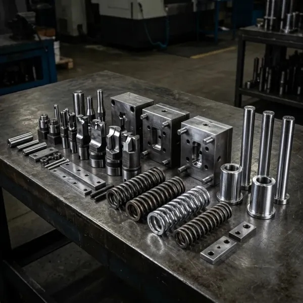
Match the steel to the zone, not to the whole die. A die body in H13 with 1.2367 inserts at the gate and H10A in the gate inserts themselves is a common high-performance build. The steel ladder is a menu of zones, not a single pick.
Heat Treatment: Hardness vs Toughness
Die steel hardness is a compromise. Too soft, and the die wears, solders, and erodes. Too hard, and it cracks on the first thermal shock. The practical window for aluminum die casting dies is roughly HRC 44-52, with the exact target set by the steel grade and the failure mode the die is most at risk of.
Hardness targets by application (typical practice): HRC 44-46 for large die bodies where toughness dominates, HRC 46-50 for standard inserts, HRC 50-54 for gate and high-wear inserts where hot hardness wins. The drawing should carry a hardness range, not a single number — heat treatment is a process, and a range is the honest spec.
Heat treatment quality shows in the tempering. A properly treated H13 die is vacuum-hardened and double- or triple-tempered to stabilize the microstructure. The goal is a fully tempered martensite with no retained austenite — retained austenite transforms under thermal cycling and distorts the die. Ask for the tempering cycle in the die spec; a one-temper shortcut is how dies crack at 15,000 shots.
Hardness verification belongs on the receiving inspection. A Rockwell or Vickers check on the die surface and a hardness map of the working zones confirms the die is what the certificate says. Dies arrive mis-treated more often than the industry likes to admit.
The EDM white layer is the heat treatment trap that shows up later. Wire and sinker EDM leave a recast layer on the surface — typically 0.01-0.05mm — that is hard, brittle, and micro-cracked. On a die casting die, that layer is where heat checking starts. The white layer must be removed by finish polishing or a secondary EDM finishing pass before the die runs. This one step extends die life measurably, and it is skipped on cost grounds all the time.
Surface Treatments: Nitriding, PVD, Boriding
Surface treatments put a hard, inert skin on the die where soldering and erosion happen. They are not a substitute for the right steel or the right cooling — they are the third line of defense, and they are most effective when the first two are in place.
Nitriding (gas or plasma) builds a diffusion case of 0.05-0.15mm at 900-1,100 HV on H13-class steels (typical values). The nitride layer resists soldering and improves wear. Nitriding before the die runs, and re-nitriding at maintenance intervals, is the standard practice on aluminum dies. Plasma nitriding has the edge on complex geometry because it avoids edge buildup.
PVD coatings — TiAlN and AlCrN classes — deposit a thin, hard film with working temperatures up to about 900°C for TiAlN-class coatings. PVD shines on ejector pins, cores, and slides where the mechanical wear is high. The coating is thin (2-5 microns typical), so the substrate still needs its own hardness.
Boriding produces a very hard, very brittle case (1,600-2,000 HV typical) that is excellent against soldering and washout on gate zones. It is a specialty treatment: the case is brittle, so it suits stationary inserts, not impact-loaded moving components.
Sequence the treatments correctly. Nitride before PVD if both are used. Never nitride a die that has been repaired by welding without re-treating the welded zone — the weld metal has a different hardenability and the surface treatment will not behave the same.
Treatment records belong in the die book: which process, which zone, what case depth, what date. Without records, re-nitriding becomes guesswork and the die runs with a worn-out case until the heat checking starts.
Cooling Channel Design: The Thermal Balance
The die face sees a thermal cycle every shot: heated by the metal, cooled by the spray and the channels. The die designer's job is to make that cycle as small as possible — keep the surface temperature within a working band, not swing between extremes. Every 50°C of surface temperature swing is thermal fatigue fuel.
Cooling channels should sit at a distance from the cavity surface that balances cooling effect against die strength: roughly 1.2-1.5x the channel diameter from the surface is the common starting rule (typical practice). Channels run 6-12mm in diameter for aluminum dies, drilled in patterns that follow the cavity contour where possible. The die should not be cooled to the point of spray-out — a die that runs too cold solders and sticks parts, which is the opposite failure.
The flow matters as much as the channel position. Turbulent flow moves heat; laminar flow does not. Design for a flow rate that keeps the water turbulent in every channel, and verify flow at commissioning with a flow meter. A "cooled" die with laminar flow in half its channels is a die with hot spots.
Conformal cooling — channels that follow the cavity contour instead of straight drilling — is available for dies through 3D-printed inserts in maraging or H13-class material. On deep cores and ribs where straight drilling cannot reach, conformal channels cut the local temperature and the heat checking with it. The printed insert is machined to finish after printing, so the cavity surface quality is unaffected.
Balance the die thermally, not just the channels. The gate zone runs hottest and should get the coldest, closest cooling; the ejector zone runs cooler. A die that is thermally balanced across its zones heat-checks evenly — which is the definition of a die that lives to its design life.

Designing for Die Life: Fillets, Draft and Stress Relief
Die life is designed in at the CAD stage. The die designer controls the stress concentrations that become heat-check nucleation sites.
Fillets and radii. Every internal corner of the die cavity is a stress concentration. A sharp corner on the die face is where the first heat-check crack will start. Internal die radii should be 1.5-2x the local wall thickness of the casting where possible (typical guideline) — the casting design and the die design are the same conversation. If the casting print demands a sharp corner, the die gets a radius and the casting gets a fillet; there is no third option that survives.
Draft. Draft on the die walls does two jobs: it helps the casting eject (which protects the die from drag) and it thickens the die cross-section at the surface where the thermal load is highest. The draft minimum for die casting is typically 1-2 degrees on side walls, more on deep cores.
Stress relief on the die block. Large die blocks carry residual stress from machining and from the original forging. A stress-relief cycle before the final machining — and before hardening where applicable — keeps the die dimensionally stable under thermal cycling. Skip it and the die distorts in service, showing up as flash that worsens over the run.
Ejector layout. Cores and deep ribs take the worst thermal load. Ejector pins placed on the hottest zones do double duty: they eject the casting and they act as cooling elements. A core that sticks is a die that overheats locally, and the fix is more draft or more pins — both designed, neither retrofitted.
Maintenance: The 10,000-Shot Checkpoint
Die maintenance is a checkpoint schedule, not an emergency response. The standard cadence on aluminum dies (typical practice): inspect every 10,000 shots, deeper service every 30,000-50,000 shots, and a full teardown at 100,000 shots or on a calendar interval, whichever comes first.
At the 10,000-shot checkpoint, do the six checks that catch the mechanisms early:
- Dye-penetrant or magnetic-particle inspection of the working zones — catches heat checking before it is visible to the eye. A crack under 0.3mm is a watch item; over 0.3mm it gets ground out or welded.
- Gate and gate-land measurement — erosion opens the gate. Compare the measured gate size to the drawing; a gate opened 10% changes the fill pattern.
- Surface condition at the gate and flow path — early soldering shows as a dull or streaked zone. Polish it out while it is shallow.
- Cooling channel flow verification — measure flow per channel against the commissioning record. A channel that lost 20% flow is scaling or blocked.
- Ejector pin projection and fit — pins that have grown (soldering on the tip) or worn change the ejector marks on the casting.
- Die face temperature check — a thermocouple or thermal camera reading at the same point every time builds the trend line that predicts the failure.
The checkpoint records are the die's health chart. Die life is managed on trends: gate size over time, crack depth over time, flow over time. A die with a trend chart gets repaired before failure; a die without one gets repaired after.
Lubrication and spray are part of the same discipline. The die release agent protects the surface and controls temperature; the spray pattern and the concentration belong in the process spec, with records. A release-agent change is a die-life change, and it should be treated as one.
Repair and Weld: When a Die Can Be Saved
A die that is heat-checked, soldered, or locally eroded is repairable — most of the time. The repair decision is a cost comparison: weld and re-machine the affected zone versus a new insert versus a new die.
Welding is the standard repair for local damage. The die is preheated to the steel's specified range — typically 300-400°C for H13-class — welded with a matching filler, stress-relieved, re-machined, and re-treated. The welded zone must be re-nitrided or re-coated to match the surrounding surface. A welded and correctly re-treated die runs nearly as long as the original; a welded die that skips the re-treatment fails again at the weld line.
Insert replacement wins when the damaged zone is an insert or can be made one. Gate inserts, core inserts, and slide inserts are designed to be replaced; swapping a gate insert costs a fraction of a die repair and resets the clock on the highest-wear zone.
Re-cutting the die surface applies when the damage is shallow and uniform — heat checking that has not penetrated. The surface is ground or machined down below the crack depth, re-polished, and re-treated. Re-cutting resets the surface but removes die material, so it works twice, maybe three times, before the die geometry is gone.
The crack-depth measurement decides the path. Dye penetrant shows surface length; sectioning or ultrasonic testing shows depth. A die with cracks below 0.3mm deep is a polishing candidate. A die with cracks to 1mm is a weld or insert job. A die with cracks through the wall is a new die — and a sign the maintenance schedule was skipped, not that the die was bad.
Measure Die Life: What to Track
Die life is a number you can manage only if you record it. The die book should carry, per die:
- Shot count at every inspection, with cumulative total
- Gate dimensions measured at every checkpoint
- Crack map (location, length, depth) from each dye-penetrant inspection
- Cooling flow per channel with trend
- Die face temperature at a fixed reference point
- Repair log: what was welded, ground, or replaced, with dates
- Treatment log: nitriding/PVD cycles and case depths
With this record, the die's life curve is visible: gate erosion rate, crack growth rate, and the shot count where each mechanism accelerates. The curve turns a die from an unpredictable cost into a scheduled cost.
Benchmark against the published bands too. If an aluminum die dies at 40,000 shots and the class average is 50,000-150,000, something in the chain is wrong: steel, heat treatment, cooling, or maintenance. The band is wide, and a die inside the band is normal. A die outside it is a diagnosis, not a statistic.
Frequently Asked Questions
Q1. How long does a die casting die last?
Aluminum die casting dies typically run 50,000 to 150,000 shots before major repair (published range). Zinc dies run longer — often 300,000+ shots. The spread within each material is decided by steel grade, heat treatment, cooling design, and maintenance discipline.
Q2. What is the best steel for a die casting die?
H13 is the baseline (HRC 44-52). For aluminum dies that run long, the DIN 1.2367 / 8418 class adds thermal fatigue resistance and typically runs 20-40% longer between repairs. Gate zones can step up to H10A-class inserts.
Q3. What causes heat checking in die casting dies?
Thermal fatigue: the die surface is heated by each shot and cooled by spray and channels, and the expansion-contraction cycle cracks the surface over thousands of cycles. It starts at stress concentrations — sharp corners, EDM white layer, rough surfaces — and accelerates with surface temperature swing.
Q4. Can a heat-checked die be repaired?
Yes, if caught early. Shallow checking (under roughly 0.3mm) is polished out. Deeper damage is welded with matching filler, stress-relieved, re-machined and re-treated. Inserts in the damaged zone are replaced. A die repaired past its service point usually fails again quickly.
Q5. Does nitriding extend die casting die life?
Yes. A nitride case of 0.05-0.15mm at 900-1,100 HV resists soldering and wear, and re-nitriding at maintenance intervals keeps the protection fresh. Nitriding complements, but does not replace, correct steel selection and cooling design.
Q6. How often should a die casting die be inspected?
Every 10,000 shots is the common checkpoint cadence, with deeper service at 30,000-50,000 and a teardown at 100,000 or on a calendar interval. Dye-penetrant inspection catches heat checking before it is visible to the eye.
The Bottom Line
Die life is a chain of decisions: steel grade matched to the zone, a hardness range that balances wear against toughness, the EDM white layer removed, cooling channels that hold the surface temperature steady, and a 10,000-shot checkpoint schedule that catches cracks while they are still polishable. Skip any link and the die dies early — not from age, but from the mechanism that link was supposed to manage.
If you are building a new die or nursing a die that is failing early, send us the die drawing and the failure history. Our engineers will spec the steel, the heat treatment and the cooling for the shot count you actually need. Start with a die design review — the die life is decided before the steel is ordered.
KEEP READING
Related Reading
5 Mold Cooling Channel Design Tips for Faster Cycles
Mold maker's 5 cooling channel design rules: channel-to-cavity distance 2-2.
Read articleArticle5 Shrinkage Compensation Rules for Mold Design
Shrinkage compensation decides mold accuracy. Five rules: material rates from 0.3% to 2.
Read articleArticle5 Ways to Reduce Mold Cost Without Cutting Quality
Five proven ways to reduce injection mold cost without cutting quality: DFM before quoting, right-sized cavity count,…
Read articleArticle7 Gate Design Best Practices for Balanced Filling
Mold maker's 7 gate design rules for balanced multi-cavity filling: gate depth 50-80% of wall thickness, land 0.5-1.
Read articleNEXT STEP
Ready to Start Your Mold?
Send us your element dimensions or part numbers — our team responds within 24 hours with pricing and lead time.

Written by
Ray ChanMold Buyer's Guide Author · Precision Mold Manufacturing Specialist. Ray helps global importers, distributors and OEMs source factory-direct molds and mold parts.