
How to Set Die Spray and Release Agent in Die Casting
Table of Contents
A 1,200 tonne die casting cell lost most of a shift when one spray nozzle plugged on cavity 3. Dilution had drifted from 1 to 80 to 1 to 40 over four days, and the die face ran 45 °C hotter at the gate. Of 1,140 housings in that run, 96 showed soldering on a boss and gas porosity under the flange. Rework consumed 9 hours of machine time and the 4,800 euro cost of the shift went into the scrap column. The fix is a spray setting that repeats on every shift, and this guide sets out the dilution, timing, flow and temperature numbers behind it.
Spray only moves heat that the die cooling layout and the gate and runner design have already decided.
The Snapshot
- Dilution runs 1 to 50 up to 1 to 150. Gate and runner zones take the richest mix and large flat faces the leanest, with one mixing station feeding every zone line.
- Spray timing is 1 to 3 s of a 60 to 90 s cycle. It starts after ejection and finishes before the die closes, and a 0.5 s timing error moves the die face 15 °C.
- Air runs at 0.15 to 0.4 MPa and mix at 4 to 8 L per hour. A plugged 0.8 mm nozzle tip cuts zone flow 30 to 70 percent and takes that zone out of control.
- Spray removes 20 to 60 °C per shot. Too little leaves soldering and heat checking, and too much produces cold laps, gas holes and ejector pin build-up.
What Die Spray Actually Does
Die spray does three jobs at once, and a setting that fixes one usually damages another. The film releases the casting, it removes heat from the die face, and it lubricates the gate and runner where metal slides at 30 to 60 m/s.
Release is the job operators notice first. A water-based agent leaves a 3 to 12 µm parting film on the cavity face, and that film stops aluminium from welding to H13 steel. Without it the casting sticks, and ejection tears 0.2 to 0.5 mm of surface out of the part.
Thermal regulation is the job that decides die life. Every shot leaves the die face 30 to 60 °C above setpoint, and the spray is the only device in the cell that takes that heat back out. Water carries most of it: 1 kg of water absorbs about 2.26 MJ as it boils.

Lubricity is the quiet job. At the gate the melt travels fast enough to erode steel, and a lubricating film at the gate and runner lowers that friction. The same film eases slide and ejector motion in the second half of the cycle.
Treat the three jobs as one budget. A mix rich enough to release a 12 mm boss is often too rich for a 1.2 mm wall beside it, which is why a die takes zone settings rather than one global recipe.
Dilution Ratios by Die Region
Dilution comes first because it decides release and cooling in a single number. Suppliers quote a working band from 1 to 50 up to 1 to 150, meaning one part of concentrate to 50 to 150 parts of water by volume.
A rich 1 to 50 mix carries more lubricating solids and releases a stubborn boss. It also leaves a thicker film that insulates the steel and gives up 5 to 15 percent of the cooling capacity. A lean 1 to 150 mix cools hard and releases poorly.
Set the ratio by die region instead of by die. The gate, runner and any deep core need the richest mix available, because metal there moves fastest and sticks first. Large flat faces, ribs under 2 mm and cosmetic surfaces take the leanest mix the die will release with.
| Die zone | Mix ratio (agent to water) | Share of spray budget | Why this zone |
|---|---|---|---|
| Gate, runner and sprue | 1 to 50 up to 1 to 80 | 40 to 60 percent | Highest metal velocity and the first point to solder |
| Deep cores, bosses and slides | 1 to 60 up to 1 to 90 | 15 to 30 percent | Hot spots with no cooling line inside them |
| Flat faces and ribs under 2 mm | 1 to 100 up to 1 to 150 | 10 to 25 percent | Cooling matters more than lubricity on thin sections |
| Ejector pads and parting line | 1 to 80 up to 1 to 120 | 5 to 15 percent | Stops pin build-up and parting-line sticking |
← swipe to scroll →
Table note: ratios and shares are typical working bands for a water-based aluminium die spray mixed at 1:50 to 1:150 by volume. Confirm against the agent datasheet and the mix station calibration before the numbers go into the die card.
Plunger Lubrication Is a Separate Circuit
The plunger tip and the shot sleeve are a separate lubrication problem, and the die spray never touches them. The tip runs inside a sleeve at 150 to 300 °C against metal poured at 680 °C, so it needs a high-temperature lubricant applied by a dosing unit on every shot.
Use a graphited or synthetic plunger lube at 0.05 to 0.3 g per shot for a 60 to 100 mm tip, delivered to the sleeve bore rather than the die face. Film thickness belongs in the 10 to 30 µm band. Below that band the tip galls the sleeve, and above it the excess burns into a carbon ring that scores both parts.
Keep the two circuits physically apart. A shared reservoir or a shared line lets die spray agent reach the sleeve, where its water flashes and its waxes carbonise. Plunger lube that reaches the cavity leaves gas holes and 0.5 to 2 mm black inclusions in the casting.
Check the tip clearance and the lube ring every 5,000 shots. A worn ring passes lubricant into the shot, and a tip clearance of 0.2 mm against a 0.10 mm specification lets metal flash past the tip. That flash shows up later as a stuck biscuit or a cracked sleeve.
Spray Timing Inside the Cycle
Spray timing is a thermal setting measured in seconds inside the cycle. On a 60 to 90 s cycle for a 1 to 3 kg housing, the spray window runs 1 to 3 s and sits after ejection and before the die closes.
Start too early and the spray hits the casting still on the core, which stains the part and wastes agent. Start too late and the die closes on a face that never dropped back to setpoint. A 0.2 to 0.5 s delay after the ejector return signal gives the casting time to clear.
The tolerance is tight because the face loses 20 to 60 °C per spray and gains it back from the next shot. Add 0.5 s to the spray and the face runs 10 to 15 °C colder, which shows up as cold laps and a short-shot flange. Cut 0.5 s and the gate runs 15 to 20 °C hotter, which shows up as soldering on the first deep boss.

Verify the window with a stopwatch and a thermal camera at two stations: the gate insert and the farthest cavity. Target a 40 to 60 °C difference between the pre-spray and post-spray readings at the gate, and 25 to 40 °C at the far cavity.
Full-Face Versus Spot Spray and Robot Zoning
Full-face spray covers every cavity with the same mix for the same time. It is simple, repeatable and correct for a single-cavity die with even wall sections. It becomes expensive on a multi-cavity die where one cavity carries a 12 mm boss and its neighbour a 1.5 mm wall.
Spot spray targets zones. A robot arm carrying two or three nozzles travels at 300 to 800 mm/s and holds each position for 0.3 to 0.8 s, with its own valve and mix line per zone. Six zones cover most automotive housings, and 10 to 12 zones cover a complex structural part.
Zoning pays on wall thickness spread. A 3 mm boss needs 0.8 s of spray while a 1.5 mm rib beside it needs 0.3 s, because the thin section loses heat 4 times faster per unit of volume and freezes first. Zone control lets one die hold two thermal targets in the same shot.
Rework the zone map whenever a wall changes. Dies for thin-wall housings at 1.0 to 1.5 mm usually run 20 to 30 percent less spray on the wall zones and 40 to 60 percent more at the gate.
Air Blast and Blow-Off Before the Spray
Blow-off comes before the spray, never after it. Compressed air at 0.3 to 0.5 MPa through 2 to 4 mm orifices clears flash chips, lubricant residue and the last of the release film from the previous cycle.
The blow-off also drops the face temperature ahead of the spray. A die face at 380 °C sits above the Leidenfrost point, so water-based mix beads and bounces instead of wetting. Blowing for 0.3 to 1.0 s brings the surface toward 300 to 320 °C, where droplets spread into a film instead of riding a vapour cushion.
Budget the air. A 3 mm orifice at 0.4 MPa flows 30 to 60 L/min, so a 12 orifice manifold on a 70 s cycle consumes 2.5 to 5 L of air per second while its valve is open. An undersized air line shows up as a weak far-side blast, which leaves the contaminant film in place.
Nozzle Types, Flow and Pressure Windows
Three nozzle families cover die casting, and droplet size is the number that separates them. Air atomising nozzles produce 30 to 80 µm droplets and the most even film. Hydraulic pressure nozzles produce 150 to 400 µm droplets with no air line. Static manifold nozzles are drilled orifices aimed at one zone and are the cheapest option.
Air atomising is the default on aluminium dies because a fine droplet wets the hot face and flashes in 0.2 to 0.4 s. A coarse 400 µm droplet lands as a puddle, and that puddle becomes a cold lap or a gas hole on the next shot.

The working window is 0.15 to 0.4 MPa of atomising air and 0.4 to 1.0 MPa of mixed liquid, with 4 to 8 L per hour of mix across the whole die. A 12 nozzle manifold therefore runs at 0.3 to 0.7 L/h per nozzle, which is a fine mist rather than a wash.
Verify flow by the reservoir, not by the setting. Measure the drop over 100 shots, because a nozzle that has lost 30 percent of its flow is partly blocked even when the pattern still looks even. Replace tips at 1 to 3 million cycles, or when measured flow moves more than 10 percent from the day-one value.
How Spray Moves Die Surface Temperature
The spray is a closed-loop temperature control device with 20 to 60 °C of authority per shot. Die face temperature decides three failure modes at once: soldering, gas porosity and thermal fatigue.
Aluminium dies run 180 to 250 °C at the face when the spray is set correctly. Raise that to 400 to 450 °C at the gate and iron from the melt reacts with the die steel, so metal welds to the surface and the casting tears on ejection. That reaction accelerates above 400 °C, which is why the gate zone takes the richest mix and the longest spray.
Over-spray pushes the same face to 150 to 170 °C. A cold face freezes metal before the cavity fills, and it also traps vapour from the agent under the skin as gas holes of 0.3 to 1.5 mm.

Read the die, not the gauge. A thermal camera survey within 5 s of opening at six points or more shows a spread of 5 °C or less between cavities on a balanced die. A 15 to 25 °C spread means one zone is over-sprayed and another is under-sprayed, and no global setting fixes that.
Face swings of 300 to 400 °C between shot and spray are what drive heat checking, and a die that runs 40 °C hot over its life loses 20 to 30 percent of its shot count.
Both temperature readings belong on the set-up sheet, because a week of those two numbers is the fastest way to catch a nozzle degrading.
Over-Spray and Under-Spray Penalties
Both directions of error leave a fingerprint on the casting, and the fingerprints are different enough to read from the last 20 parts.
Over-spray shows as cold laps and cold shuts on thin sections, gas holes under a machined face, and a 0.1 to 0.3 mm build-up on ejector pins and slides. On a part that is painted or plated, an over-sprayed casting often fails adhesion at the first wash because the release film is still on the surface.
Under-spray shows as soldering at the gate and runner, sticking that tears 0.2 to 0.5 mm out of a boss, and heat checking that arrives thousands of shots early. A die running 40 °C hot over its working life gives up 20 to 30 percent of its shot count.
| Symptom on the casting | Spray direction | Most likely cause | First correction |
|---|---|---|---|
| Cold lap on a 1.2 mm rib | Over-spray | Zone flow 40 percent above plan | Cut that zone to 0.3 s and re-check the pattern |
| Gas holes 0.5 mm under a flange | Over-spray | Wet film left on the face | Add 0.5 s of blow-off before the spray |
| Black deposit on ejector pins | Over-spray | Agent solids burning at 380 °C | Lean the pin zone mix to 1 to 120 |
| Soldering on the gate boss | Under-spray | Dilution drifting lean over days | Richest mix at 1 to 50 on the gate zone |
| Casting sticks on a deep core | Under-spray | No dedicated nozzle on the core | Add a nozzle and set the core zone to 0.8 s |
| Heat checks at 40,000 shots | Under-spray | Face running 40 °C above setpoint | Rebalance zones against a thermal camera survey |
← swipe to scroll →
Table note: symptoms and corrections are the common pairs seen on aluminium dies at 180 to 250 °C face temperature. Confirm the cause with a thermal survey and a flow measurement before changing a setting, because a blocked nozzle mimics over-spray on the neighbouring zone.
Count the cost of both directions. Running 1 to 40 instead of 1 to 80 doubles the concentrate bill on a cell that sprays 6 L per hour.
Water-Based Versus Solvent-Based Agents
Water-based agents dominate aluminium die casting. A working mix at 1 to 80 is about 98 percent water, so the cooling comes from the water fraction and the lubricating solids ride on top of it. The concentrate carries a rust inhibitor, a wetting agent and 1 to 5 percent of lubricating solids.
Solvent-based agents flash off faster and wet a hot face better, which suits a short cycle and thin walls where a water film would chill the surface. They cost 3 to 8 times more per part and carry 400 to 800 g/L of VOC, so they need extraction and a controlled waste stream.
Mix make-up water is the setting nobody records. Mains water at 200 to 800 µS/cm carries hardness that plates out on nozzle tips and inside the die. Deionised or softened water at 10 to 50 µS/cm keeps nozzles clean and holds the mix stable for a full shift.
Log the mix every shift. Refractometer reading within 2 percent of target, pH between 7.5 and 9.0, and conductivity within 20 percent of the day-one figure. A mix that drifts 20 percent lean inside two days has a leaking dose pump or an evaporating tank.
Daily Maintenance and the Spray Set-Up Record
Spray maintenance is a shift-start check plus a weekly measurement, and it takes 10 minutes once the sequence is written down.
Every shift: wipe the nozzle tips, check the pattern on a white card held 200 mm from the manifold, confirm the reservoir level, and look for drips at every fitting. A pattern that lost its fan shape on one nozzle pushes 15 to 25 percent of that zone flow onto its neighbours and shows up as a cold lap two cavities away.
Every week: measure flow over 100 shots, read the refractometer, check pH and conductivity, drain the air-water separator, and inspect hoses for a 0.1 mm pinhole leak. Compressed air carries 1 to 5 g/m³ of water, and that condensate dilutes the mix at the nozzle.
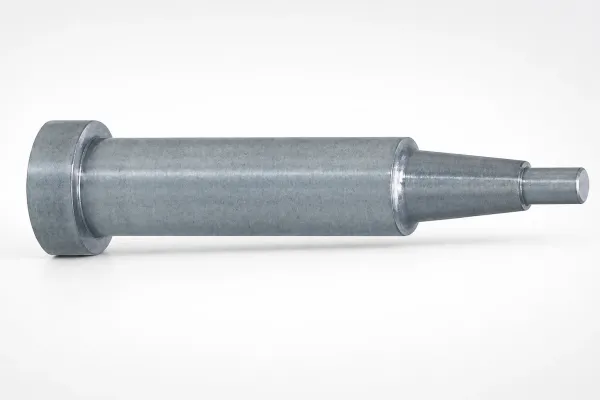
Every month: replace or re-tip nozzles at the end of their cycle count, clean the inline filter, and check the dose pump calibration. Pull the die for a spray circuit rebuild when two or more zones cannot hold their window, which is a job for die casting mold service and a change to the die record.
| Record field | Example entry | Tolerance or check |
|---|---|---|
| Die number, machine and shift | DC-4471, 1,200 t cell, early shift | One sheet per die per shift |
| Agent, batch and mix ratio | Water-based, batch 2609, 1 to 80 | Refractometer within 2 percent |
| Nozzle count, type and tip size | 12 air atomising, 0.8 mm tips | Pattern card check at 200 mm |
| Air and liquid pressure | 0.28 MPa air, 0.7 MPa liquid | Air window 0.15 to 0.4 MPa |
| Zone spray times | Gate 0.9 s, cores 0.8 s, walls 0.3 s | Total 1 to 3 s of the cycle |
| Mix flow per 100 shots | 0.55 L used over 100 shots | 4 to 8 L per hour per die |
| Face temperature before and after spray | 356 °C before, 301 °C after at the gate | 40 to 60 °C drop at the gate |
| Plunger lube dose and tip check | 0.12 g per shot, tip at 0.10 mm | Ring and clearance every 5,000 shots |
← swipe to scroll →
Table note: the sheet is written for a 12 nozzle aluminium die on a 60 to 90 s cycle. Adjust the zone count, the flow figure and the temperature band to the die card, then file the sheet with the shot count so the next changeover starts from measured numbers.
Die Spray and Release Agent FAQ
Q1. What dilution should a die spray run at?
Between 1 to 50 and 1 to 150 by volume, set by region rather than by die. Gate, runner and deep cores take 1 to 50 up to 1 to 80, large flat faces and ribs under 2 mm take 1 to 100 up to 1 to 150, and ejector pads take 1 to 80 up to 1 to 120.
Q2. Why is plunger lubrication on a separate circuit?
Because the tip runs at 150 to 300 °C against metal poured at 680 °C and needs 10 to 30 µm of high-temperature lubricant, not a water-based release film. Sharing a line lets water flash in the sleeve and waxes carbonise, and lube that reaches the cavity leaves 0.5 to 2 mm black inclusions.
Q3. How long should the spray run?
1 to 3 s on a 60 to 90 s cycle, starting after ejection and finishing before the die closes. Add 0.5 s and the face runs 10 to 15 °C colder, which raises cold laps. Cut 0.5 s and the gate runs 15 to 20 °C hotter, which raises soldering.
Q4. How do I tell over-spray from under-spray?
Over-spray gives cold laps and shuts on thin sections, gas holes of 0.3 to 1.5 mm, and 0.1 to 0.3 mm build-up on pins. Under-spray gives soldering at the gate, ejection tears of 0.2 to 0.5 mm and heat checks thousands of shots early. A thermal survey inside 5 s of opening separates them in one shift.
Q5. What pressure and flow should the spray circuit hold?
0.15 to 0.4 MPa of atomising air, 0.4 to 1.0 MPa of mixed liquid, and 4 to 8 L per hour of mix across the die. On a 12 nozzle manifold that is 0.3 to 0.7 L/h per nozzle, verified by measuring the reservoir drop over 100 shots.
Q6. Why does the mix drift lean during a shift?
Three causes cover most cases: a leaking dose pump, an evaporating tank on a warm cell, and make-up water above 200 µS/cm hardness. Check the refractometer against the conductivity reading, because a 20 percent lean drift inside two days is a hardware fault rather than an operator error.
The Bottom Line
Die spray is a thermal control loop rather than a wipe. Four numbers keep it in control: mix ratio between 1 to 50 and 1 to 150 by region, a 1 to 3 s spray window inside a 60 to 90 s cycle, 0.15 to 0.4 MPa of atomising air with 4 to 8 L per hour of mix, and a 20 to 60 °C face drop on every shot.
Over-spray and under-spray both cost money, but they cost it in different places. One side gives cold laps, gas holes and ejector pin build-up. The other gives soldering, ejection tearing and a die life cut by 20 to 30 percent. The zone map, the thermal survey and the set-up sheet are what tell the two apart inside one shift.
DieStrike builds H13 and 1.2343 die casting dies with conformal cooling and a documented spray circuit layout, under IATF 16949 process control and plus or minus 0.005 mm mold tolerance, plus or minus 0.002 mm on EDM and jig-ground features, heat treatment to HRC 62 maximum, 120 or more machines and tier-1 programs for TE, Amphenol, Luxshare and Dongshan. Standard components ship in 3 to 7 days and die lead times run 2 to 5 weeks. Send the die drawing, the current spray sheet and the face temperature readings, and we will return a zone map with mix ratios, nozzle positions and cycle times.
KEEP READING
Related Reading
Die Casting Mold Manufacturing
H13 dies with conformal cooling, spray circuit layout and IATF 16949 process control on 2 to 5 week lead times.
Read articleArticleHow to Select Mold Steel for Die Casting Dies
H13, 1.2344 and 1.2343 grades, hardness bands and the heat check resistance each one buys.
Read articleArticleHow to Extend Die Casting Mold Life
Shot counts, cooling balance, welding rules and the maintenance steps that push a die past 100,000 shots.
Read articleArticleZinc vs Aluminum Die Casting
Melting range, die temperature and cycle differences that change the spray recipe and the tool steel choice.
Read articleNEXT STEP
Ready to Start Your Mold?
Send us your element dimensions or part numbers — our team responds within 24 hours with pricing and lead time.

Written by
Ray ChanMold Buyer's Guide Author · Precision Mold Manufacturing Specialist. Ray helps global importers, distributors and OEMs source factory-direct molds and mold parts.