
How to Design Die Casting Die Cooling: Thermal Balance and Die Life
Table of Contents
A 2.5 kg aluminium transmission housing left the press with a 0.9 mm soldered patch on a gate-side boss at 41,000 shots. The die had four 10 mm cooling lines in the cavity insert and none in the slide. The core ran 80 °C hotter than the cavity face, the spray nozzles could not reach the boss, and the tool came back to the bench for a new insert and a second circuit. Eight production days, about 96,000 castings and one full re-cut sat on that missing line.
Die cooling is a heat balance problem before it is a plumbing problem. Aluminium enters the shot sleeve at 650 to 700 °C and leaves the die at 200 to 250 °C. Every kilogram of casting must give up roughly 760 kJ of enthalpy, and the die has to remove that heat at the same rate it arrives. Let removal fall 10 percent behind and the die face climbs a few degrees per shot until it crosses into soldering and heat checking.
This guide covers the thermal side of a die casting die: heat load accounting, channel placement in the cavity, core, slide and sprue, baffles, bubblers and jet cooling at hot spots, die temperature targets of 150 to 250 °C, water flow and Reynolds number targets, die spray interaction, thermal fatigue, soldering control with PVD coatings and thermography based tuning. Gate and runner geometry, venting and hot-work steel selection each carry their own numbers. The tool body itself comes from our die casting mold service, and every figure below needs checking against the alloy data sheet and the machine before a drawing is released.
The Snapshot
- About 760 kJ per kg of enthalpy. Aluminium releases roughly 390 kJ/kg of latent heat plus sensible heat from 660 down to 200 °C. A 2.5 kg shot at 100 shots per hour puts 30 kW into the die.
- Heat split of 45 to 60 percent to water. Cooling circuits carry the largest share, die spray carries 25 to 40 percent, and radiation with convection carries 5 to 15 percent.
- Die face held at 180 to 230 °C for aluminium. Below 150 °C the metal freezes before it fills; above 300 °C the surface starts to solder.
- Reynolds number above 10,000 per circuit. Turbulent water in a 12 mm channel moves 10 to 14 L/min at 1.5 to 2.5 m/s and delivers 3,000 to 8,000 W/m²K.
Why Die Cooling Decides Die Life
A die casting die is a heat exchanger that happens to produce parts. Every shot delivers a fixed heat load, and the die discharges it through three paths only: the cooling circuits, the die spray, and radiation with convection. When those paths remove less than the shot delivers, the surface temperature climbs and the process drifts.
The drift is neither gradual nor harmless. A die face above 300 °C starts to alloy with the aluminium, the first stage of soldering. Above 450 to 500 °C the surface layer softens and heat check cracks open at the gate and around bosses.

The cost of a thermal mistake shows up three ways. Rejects from cold shuts, flow marks, soldering and blistering rise as soon as the face drops below 150 °C or climbs past 260 °C. Cycle time stretches by 5 to 12 seconds whenever a circuit cannot pull heat fast enough, because the operator has to buy time with a longer spray. Die life falls as well: each 20 °C of sustained extra surface temperature can take 10 to 15 percent off the shot count before heat checking.
Two numbers anchor the whole design: the heat load per shot, which sets the water flow requirement, and the allowable surface temperature band, which sets channel distance, pitch and spray time. Machine settings can hide a bad thermal layout for a shift, but the steel geometry cannot. A die that needs water where no channel exists will not be tuned into balance.
Heat Load Accounting Per Shot
Start with the enthalpy that the casting gives up inside the die. Aluminium has a latent heat of fusion of about 390 kJ/kg and a solid specific heat near 0.9 kJ/kg·K. A casting that arrives at 660 °C and leaves the die at 220 °C therefore releases roughly 390 plus 440 times 0.9, which is about 786 kJ per kg.
Not all of that heat enters the steel. The spray removes heat from the surface, the shot sleeve takes heat from the biscuit, and radiation carries a small share into the air. Field measurements on aluminium cells usually put 50 to 60 percent of the casting enthalpy into the die body. Treat 55 percent as the design default and confirm it on the trial with a flow meter and a temperature logger.
Convert that share into power, because power is what the circuits must match. A cell running a 2.5 kg shot at 100 shots per hour processes 250 kg of metal per hour. At 786 kJ/kg and a 55 percent share, the die absorbs about 108,000 kJ/h, which is 30 kW. A 5 kg shot at 60 shots per hour works out to 300 kg/h and 36 kW. Water at a 4 °C rise across the circuit carries about 3.6 kW per 10 L/min, so a 30 kW load needs roughly 108 L/min of total flow.
Allow an extra 10 to 15 percent on a cold chamber machine, where the shot sleeve, the plunger tip, the sprue and the overflow wells all sit in the thermal path. Give the sleeve its own circuit rather than tapping it off the cavity header.
| Shot mass | Shots per hour | Metal per hour | Heat into the die | Water flow at a 4 °C rise |
|---|---|---|---|---|
| 0.8 kg | 150 | 120 kg/h | 14 kW | 50 L/min total |
| 1.5 kg | 120 | 180 kg/h | 22 kW | 79 L/min total |
| 2.5 kg | 100 | 250 kg/h | 30 kW | 108 L/min total |
| 5.0 kg | 60 | 300 kg/h | 36 kW | 130 L/min total |
| 9.0 kg | 40 | 360 kg/h | 43 kW | 155 L/min total |
← swipe to scroll →
Table note: figures assume an aluminium alloy at 786 kJ per kg, a 55 percent share into the die body and a 4 °C water temperature rise. Magnesium runs about 5 percent lower and zinc about 75 percent lower for the same shot weight.
Zinc carries far less heat than aluminium. With a latent heat near 110 kJ/kg and a specific heat of about 0.42 kJ/kg·K, a Zamak casting that leaves the die at 180 °C releases roughly 190 kJ/kg, so a zinc die needs about a quarter of the aluminium water flow for the same shot weight.
Cooling Line Placement in Cavity and Core
Two numbers decide how well a drilled line works: its distance from the cavity surface and the pitch between neighbouring lines.
For aluminium dies, a 12 mm channel is the common size, placed 20 to 30 mm from the cavity surface and repeated on a pitch of 3 to 5 times the diameter, so 36 to 60 mm. Keep at least 15 mm of solid steel above the channel crown, because cavity pressure during intensification reaches 700 to 1,000 bar and a thin steel roof above a drilled line will eventually crack or deform. Move the channel closer than 15 mm and heat checking appears along the channel line within 30,000 to 50,000 shots.
Cooling has to follow the mass, not the outline. A 25 mm thick boss next to a 3 mm wall runs 60 to 90 °C hotter than the wall unless it gets its own line, baffle or insert. That single hot spot is where soldering begins. On a housing with four bosses and a central core, the thermal job is usually three circuits on the cavity, two on the core and one on the boss cluster.

Where a channel cannot reach, a high-conductivity insert takes over. Copper-beryllium and copper alloy inserts run three to four times the thermal conductivity of H13, so a hot spot relieved with a copper insert cools almost as well as a properly placed line. The trade is wear and heat checking: keep copper inserts off shut-offs, gate lands and any surface that sees metal velocity above 40 m/s.
Target a face variation of ±10 °C across the cavity at steady state. That is achievable with six to twelve circuits, each between 10 and 14 L/min, and a header sized so the last circuit sees no less than 90 percent of the flow of the first. Pressure drop across a clean 12 mm circuit lands between 0.5 and 1.5 bar, with 3 to 5 bar at the machine.
Label every circuit on the drawing and on the die itself. A die that runs 12 L/min in the trial and 7 L/min a year later is usually a die whose circuits were never identified, cleaned or logged.
Slide and Sprue Cooling
A slide sits outside the spray shadow and carries a heavy section, so it runs hot by design. A slide with no circuit reaches 60 to 120 °C above the cavity face inside the first 500 shots. That temperature gap opens the fit, wears the wear plates and closes the guiding clearance until the slide starts to bind or flashes.
Most slide blocks have room for 8 to 10 mm channels. Where the block is 60 mm or thicker, run two parallel 10 mm lines through the body and link them with a drilled cross passage. Where the block is thin, use a baffle or a bubbler instead of a large channel, and keep the steel roof above the passage at 12 mm minimum. Hose the circuits with EPDM line rated to 120 °C, or fit a rotary coupling when slide travel exceeds 60 mm, because a hose that kinks once a shift will stop the flow that keeps the slide straight.
Take thermal growth seriously on long slides. Steel expands about 12 µm per metre per degree, so a 300 mm slide running 100 °C above the cavity face grows roughly 0.36 mm. That growth alone can consume a 0.05 mm guide clearance and load the wear plates on every shot.
Cool the sprue as well. In a cold chamber machine the biscuit, runner and overflow wells often hold 30 to 50 percent of the shot mass, and that metal gives up its heat beside the sprue pin. A 10 mm baffle in the sprue hole, fed with the sprue spreader, shortens biscuit solidification and typically takes 2 to 5 seconds off the cycle on a heavy part.
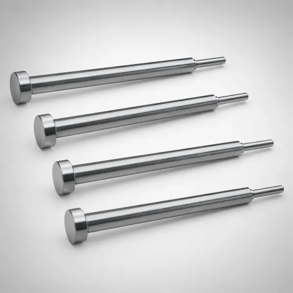
Put platen connections, quick couplers and a flow meter on each circuit in the drawing set as well, and specify a header that can be isolated circuit by circuit. A die that cannot be diagnosed circuit by circuit is diagnosed by scrap rate instead.
Baffles, Bubblers and Jet Cooling
Straight drilled lines cannot reach the middle of a core or the tip of a slender pin, so the thermal design uses three standard tools. A baffle splits a drilled hole into a down leg and an up leg. A bubbler carries water to the tip of the hole and returns it through the annulus. A jet tube drives water at speed against the inside of a closed tip.
Match the tool to the hole size. Baffles suit cores of 15 to 30 mm diameter with a drilled hole of 8 to 12 mm. Bubblers suit holes of 8 to 20 mm, where a 5 to 6 mm tube leaves a 2 to 3 mm annulus for the return. Jet tubes belong in deep cores and pins above 6 mm diameter, where the tip is the hot spot. Below 6 mm there is no room for internal cooling, and the pin needs a high-conductivity alloy instead.
Account for the efficiency loss. A baffled hole delivers roughly 50 to 70 percent of the heat transfer of a straight channel of the same diameter, and a bubbler lands at 40 to 60 percent, because the return path carries water that has already picked up heat. A jet tube running 4 to 8 m/s at the tip can beat a straight channel locally by 20 to 40 percent, which is why it is the standard answer for a deep core tip and for a hot pin in a heavy boss.

Design the air out of the circuit. A bubbler or baffle traps air at the top of the hole, and the pocket insulates the tip. Fit a 1 to 2 mm bleed at the high point, or run the circuit at 3 to 4 bar. An airlocked bubbler shows up as a core tip that stays 40 to 60 °C hot within 200 shots, with a shrinking boss on the casting.
Material choice multiplies the effect. H13 conducts about 25 to 30 W/m·K, while beryllium copper and copper alloys run 105 to 200 W/m·K, so a copper alloy core tip removes three to four times the heat of the same steel tip. Use that on the boss cluster and on thin, tall cores, and keep copper away from the gate and from any shut-off face where wear has to stay low.
Verify each circuit after assembly, not after the first scrap report. A bubbler should pass 5 to 10 L/min at 2 to 3 bar, a baffled 10 mm hole 8 to 12 L/min, and a jet tube 4 to 8 L/min. Rod the passages out at every maintenance window, because a 0.3 mm film of scale in a bubbler annulus can halve the flow without changing the pump reading at the header.
Die Temperature Targets by Alloy
The die face band is set by the alloy and the wall thickness, not by operator preference. Aluminium runs 180 to 230 °C on general work. A thin wall of 1.0 to 1.5 mm needs 230 to 280 °C so the metal fills the far rib before it freezes, while a 6 mm wall in the same alloy is happy at 180 to 200 °C. Run a thin-wall die at heavy-section temperatures and the tool solders at the gate within 20,000 shots.
| Alloy family | Melt temperature | Die surface target | Enthalpy to the die | Typical cycle |
|---|---|---|---|---|
| Aluminium ADC12 and A380 | 650 to 700 °C | 180 to 230 °C | 780 to 800 kJ/kg | 40 to 90 s |
| Aluminium thin wall | 680 to 720 °C | 230 to 280 °C | 780 to 800 kJ/kg | 15 to 35 s |
| Magnesium AZ91D | 640 to 680 °C | 200 to 260 °C | 730 to 760 kJ/kg | 30 to 70 s |
| Zinc Zamak 3 and 5 | 400 to 420 °C | 150 to 200 °C | 180 to 200 kJ/kg | 10 to 30 s |
| Magnesium thin wall | 660 to 690 °C | 240 to 280 °C | 730 to 760 kJ/kg | 20 to 45 s |
← swipe to scroll →
Table note: bands are typical industry values for cold chamber dies on a 55 percent heat share. Confirm the melt temperature against the alloy certificate and the die targets against the machine and the spray programme on the trial.
Judge the face by its spread, not its average. Hold the spread within ±15 °C across the cavity and within ±20 °C between cavity and core on the same shot, and cold shuts and soldering drop together.
Water Flow and Reynolds Number
Flow that is barely moving carries very little heat, which is why the design target is never just litres per minute. The Reynolds number describes the flow regime: density times velocity times channel diameter, divided by dynamic viscosity. Water at 25 °C has a density of 997 kg/m³ and a viscosity near 0.89 mPa·s, so a 12 mm channel reaches a Reynolds number of 10,000 at about 0.74 m/s.
The regime decides the heat transfer coefficient. Laminar flow below a Reynolds number of 2,300 gives 500 to 1,000 W/m²K. Fully turbulent flow above 10,000 gives 3,000 to 8,000 W/m²K, which is the difference between a die that balances and a die that climbs in temperature all shift. The transitional band between 4,000 and 8,000 is worth avoiding altogether, because the coefficient moves with small changes in flow and the die never settles.
Size the circuit around that velocity. A 10 mm channel at 2 m/s carries 9.4 L/min, a 12 mm channel carries 13.6 L/min, and a 14 mm channel carries 18.5 L/min. Where the pump cannot deliver 2 m/s in every circuit, use smaller channels instead of accepting laminar flow in large ones. Six turbulent 10 mm circuits at 9 L/min move more heat than six 14 mm circuits at 4 L/min, and the smaller channels cost less to drill.
Log the flow and the rise across every circuit at commissioning, then again at month one, three and six. An inlet at 35 °C that leaves 1 to 3 °C warmer is healthy; a 10 °C rise means the flow is roughly half of what the drawing asked for.
Treat scale as a primary enemy. Hard water above 200 mg/L as calcium carbonate coats the channel wall, and 0.5 mm of scale adds more thermal resistance than the water film itself, cutting heat transfer by 20 to 40 percent. Flush with a 5 to 10 percent citric or sulfamic acid solution at 40 to 50 °C when flow drops 10 percent from the commissioning value. Standard cooling components such as baffles, jet tubes and manifolds only perform to the level the circuit condition allows.
A closed loop with a 10 µm filter keeps the passages free of debris, and an open loop on a plant header carries rust into a 10 mm channel and closes it in a season.
Die Spray Interaction and Balance
Die spray does two jobs at once: it releases the casting, and it removes 25 to 40 percent of the heat load. A typical programme runs a water based release agent diluted 1:100 to 1:200, through nozzles of 1.0 to 1.5 mm at 3 to 5 bar of air, delivering 20 to 60 mL per second per nozzle across the working face.
Understand what the spray can and cannot do. Evaporating water absorbs about 2.26 kJ per gram, so a two second pass over a 0.6 m² die face, which deposits 100 to 200 mL of diluted fluid, does remove a real share of the heat. That phase change happens on the surface, in the areas the nozzle can see. It does nothing for a slide that faces away, or for the tip of a core 80 mm deep in a pocket.
That gap is where thermal balance breaks. When a die runs hot, the operator lengthens the spray time and the outer face cools, so the casting looks better at the next inspection. The core and the slide stay hot because the water never reached them. Fifty thousand shots later the core tip is heat checked and the slide is soldered, with a spray programme optimised for the wrong temperature.

Fix the balance with the circuits, then trim with the spray. Circuit flow sets the baseline temperature of the whole die; spray trims the surface, controls release and protects the hot spots that the nozzles can reach. A die with correct circuits and a two second spray runs a stable cycle. A die with weak circuits and a six second spray runs a slow cycle with a hot core, and it consumes twice the release agent to do it.
Log the spray time, dilution, air pressure and nozzle positions on the setup sheet, because those four settings move the die face as much as the water does.
Thermal Fatigue and Heat Checking
Every shot puts the die surface through a full thermal cycle. The face sits at 200 °C, jumps to 450 or 500 °C under the melt in a fraction of a second, and is pulled back down by the spray and the circuits. The surface layer tries to expand and is held by cooler steel a few millimetres below, so it yields in compression on every fill and in tension on every spray.
That cycle repeats hundreds of times an hour, and the steel cannot take it forever. Heat check cracks appear as a fine network with cell size of 1 to 4 mm and depth of 0.2 to 1.0 mm. In aluminium service, H13 at HRC 44 to 48 usually starts checking somewhere between 50,000 and 150,000 shots, and the range is driven almost entirely by surface temperature. Each 20 °C of sustained extra face temperature can cost 10 to 15 percent of the interval before the cracks need welding.
Slow the damage with geometry and temperature. Radius every internal corner to R0.5 minimum, keep the surface between the water lines polished to Ra 0.4 µm, and hold the face under 450 °C at every point. Sharp edges at the gate, a chipped gate land and a sharp boss root all concentrate the strain and become the first places to check. A die that heat checks in a network around one corner is telling you where the thermal gradient is steepest, not where the steel was bad.
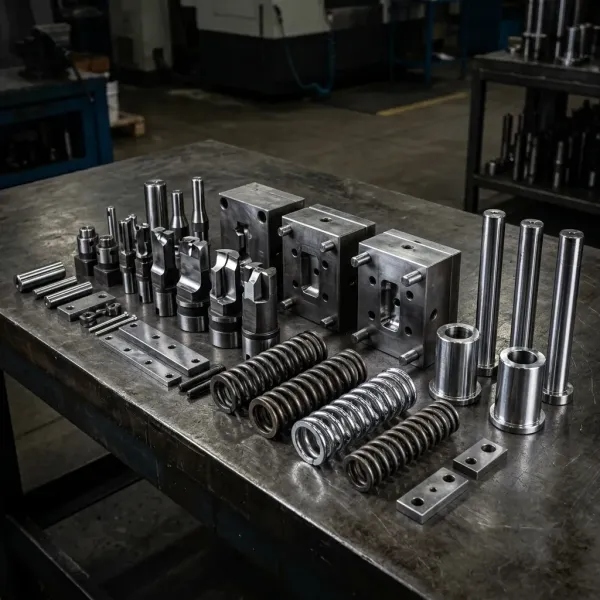
Repair on a schedule rather than at failure. Inspect the face with dye penetrant and a 10x loupe every 20,000 to 30,000 shots, and weld repair once cracks pass 0.5 mm depth. Preheat the insert to 350 to 400 °C before welding, use a matching H13 filler, and temper at 550 °C for two hours after welding to bring the repaired zone back to the parent hardness. A repair done cold leaves a hard, brittle patch that checks again inside 10,000 shots.
Stress relief pays for itself. An H13 insert that gets a 550 °C stress relief after the first 50,000 to 100,000 shots resists checking longer than one that never sees the furnace.
Soldering Control with PVD Coatings
Soldering is the failure that removes aluminium from the casting and puts it on the die. Above roughly 450 °C the aluminium reacts with the iron in the steel and forms hard iron-aluminium intermetallic layers. Once that layer is established, the die keeps grabbing metal, the casting comes out with a rough patch and a dimensional shift, and the defect grows with every shot.
Attack the cause before the surface. Soldering starts at a hot spot with no spray reach, at a gate where metal velocity is excessive, or on a die that runs too cold so the melt freezes against the wall and drags. On heavy aluminium sections, hold gate velocity between 30 and 45 m/s; on thin wall parts, 45 to 60 m/s. Keep the face above 180 °C so the melt does not freeze on the steel, and put a circuit or an insert under any boss that cannot be sprayed.
Coatings are the second line and they work on the areas they cover. Physical vapour deposition layers of AlCrN, TiAlN or CrN at 2 to 5 µm carry hardness of 2,500 to 3,200 HV, well above the 45 to 50 HRC of the H13 substrate. Coat the gate insert, the sprue spreader, the boss cores and any face that has soldered before, and plan on stripping and recoating the gate area every 50,000 to 150,000 shots.
Gas nitriding is the traditional alternative and still has a place on low-volume and zinc tools. A nitrided layer of 0.10 to 0.20 mm raises surface hardness and reduces adhesion, but it can spall under severe thermal cycling on an aluminium die. A thin PVD layer barely affects heat transfer, while a 0.2 mm nitrided case can push the face 10 to 20 °C hotter under the same conditions.
Thermography Based Tuning
Thermal tuning works with a camera rather than with opinion. An infrared camera with at least a 320 by 240 detector reads the die face during the cycle, and on an oxidised steel surface an emissivity setting of 0.7 to 0.8 gives a usable absolute value. Hold the machine at steady state for 200 to 300 shots before the pass, or the map will describe a die that no longer exists.
Run two passes. First, image the die at the end of the dwell with the casting out and before the spray, which shows the heat pattern left by the shot and highlights any area that is not getting water.
Read the map with thresholds. A patch 40 to 60 °C above its neighbours points to a blocked or missing circuit, a heavy section, or an airlocked bubbler. A patch 30 °C below its neighbours points to over-cooling: flow too high, a channel too close to the surface, or a spray nozzle pointed at a thin wall.
Change one thing at a time: adjust the flow on a single circuit, wait 100 shots, image again, then record the setting. Every number on the sheet then has a reason attached.
The thermal work starts before the first cut. The DFM review sets channel position, pitch and slide circuits from the part geometry, and T1 sampling confirms the layout with thermocouples and a camera on the real machine. Keep the thermal map, the flow per circuit, the spray programme and the insert temperatures in the tool file. When the first insert is re-cut at 100,000 shots, that record is the starting point for the next one instead of a guess.
Die Cooling Design FAQ
Q1. How much cooling water does an aluminium die casting die need?
Work from the heat load. At 786 kJ/kg and a 55 percent share into the die, a 2.5 kg shot at 100 shots per hour puts about 30 kW into the steel, which needs roughly 108 L/min of total flow at a 4 °C rise. Split that across 6 to 12 turbulent circuits, each carrying 10 to 14 L/min at 1.5 to 2.5 m/s.
Q2. What water temperature should a die casting die run?
A 25 to 35 °C inlet is normal for aluminium. The die face then sits at 180 to 230 °C on general work and 230 to 280 °C on thin walls, which is 150 to 250 °C above the water temperature. Glycol at 30 to 40 percent is needed only when a circuit is asked to run below 20 °C.
Q3. Why does my die run hot even with full water flow?
Check three things in order: a circuit that is scaling shut, so flow at the header looks right while the rise across the circuit is 8 to 10 °C; a hot section with no channel near it, such as a slide or a boss cluster; and a bubbler or baffle that has airlocked. Each of the three leaves the face 40 to 100 °C above its neighbours.
Q4. What is the fastest way to stop soldering on an aluminium die?
Cool the hot spot first, because soldering is a temperature problem before it is a surface problem. Add a circuit, baffle or copper insert under the boss, keep the face above 180 °C, hold gate velocity at 30 to 45 m/s on heavy sections, then coat the gate insert and affected cores with AlCrN or TiAlN at 2 to 5 µm.
Q5. When should a heat checked insert be replaced rather than welded?
Weld repair is the right answer while cracks stay under 0.5 mm depth and the network is local, with preheat at 350 to 400 °C and a 550 °C temper afterwards. Replace the insert when cracks pass 1.0 mm, when they cross a seal land or a gate land, or when the repaired area checks again inside 10,000 shots.
The Bottom Line
Die cooling comes down to four numbers: 760 kJ per kg of enthalpy entering the steel, a face band of 180 to 230 °C for aluminium, a Reynolds number above 10,000 in every circuit, and heat checking that starts between 50,000 and 150,000 shots depending on how hot that face really runs. Hold those four and the die balances. Miss any one and no spray programme recovers it.
DieStrike builds die casting dies and precision injection molds to IATF 16949, with ±0.005 mm mold accuracy and ±0.002 mm on EDM and jig grinding, HRC 62 maximum cavity heat treatment and more than 120 machines. Standard components ship in 3 to 7 days and tool lead times run 2 to 5 weeks, with tier-1 programmes for TE, Amphenol, Luxshare and Dongshan. Send the part geometry and the alloy and our team will return a cooling concept with channel positions, circuit flows and thermal targets before any steel is cut.
KEEP READING
Related Reading
Die Casting Mold Manufacturing
Aluminium, magnesium and zinc dies built to IATF 16949 with ±0.005 mm cavity accuracy and 2 to 5 week lead times.
Read articleProductMold Heating and Cooling Components
Baffles, bubblers, jet tubes, fittings and temperature controllers that hold a circuit within ±1 °C.
Read articleArticleHow to Clean Mold Cooling Channels
Scale, rust and polymer fouling cut flow rate and heat transfer. Cleaning intervals and acid selection.
Read articleServiceMold Design and DFM Review
Cooling layout, gate placement and steel choice checked against the part drawing before the first cut.
Read articleNEXT STEP
Ready to Start Your Mold?
Send us your element dimensions or part numbers — our team responds within 24 hours with pricing and lead time.

Written by
Ray ChanMold Buyer's Guide Author · Precision Mold Manufacturing Specialist. Ray helps global importers, distributors and OEMs source factory-direct molds and mold parts.