
How to Design Die Casting Dies for Thin-Wall Housings
Table of Contents
A 1.2 mm aluminum housing die that fills at 28 m/s instead of 55 m/s leaves cold shuts along the last 15 mm of the rim. The same die pushed to 70 m/s entraps air, and X-ray shows 4% gas porosity in the boss ring. Both lots scrap, and neither defect comes off the machine. Both are set in the die: the in-gate area, the thermal layout and the vent path.
Thin-wall housings are the hardest geometry in die casting. Aluminum walls run 0.8-1.5 mm typical and zinc walls run 0.5-0.8 mm typical on connectors, handset chassis and LED housings. Molten aluminum at 660-700 °C freezes across a 1 mm section in 20-40 ms, so the fill has to finish in 30-80 ms. The die must deliver that window on every shot for 100,000+ shots, with the wall staying flat to ±0.05 mm.
This guide covers the die side of that job: in-gate thickness matched to fill speed, vacuum assist, die temperature at 180-250 °C, cooling pitch, ejection layout, inserts for side holes and fins, coatings and heat-check life limits. Gate and runner sizing is not repeated here. It is covered in our fill system guide. This article stays on the die block, the thermal circuit and the ejection system.
The Snapshot
- Thin walls run 0.8-1.5 mm in aluminum at 30-80 ms fill time, and 0.5-0.8 mm in zinc at 15-40 ms (typical).
- In-gate velocity lands at 40-80 m/s for aluminum and 40-60 m/s for zinc, biased to the upper half on thin walls.
- Die temperature runs 180-250 °C for aluminum thin-wall work, held within ±10 °C across the cavity.
- Cooling channels sit on a 20-30 mm pitch behind the cavity, 12-18 mm below the surface on a 1.2 mm wall.
- Ejection runs at 5-15 kN per housing; contact pressure stays below 8 MPa to avoid punch-through and bow.
Why Thin-Wall Housings Break Die Casting Rules
Wall thickness sets everything downstream. A 3 mm wall holds heat long enough for the melt to reach the last point of fill with 10-20 ms of margin. A 1.0 mm wall loses that margin. Heat leaves the melt into the die steel at a rate proportional to surface area, and a thin section has little volume to store it. Fill time becomes the only variable that keeps the front flowing.
The flow length to thickness ratio is the number that decides feasibility. A 160 mm flow path through a 1.0 mm wall gives L/t of 160. Aluminum dies handle L/t of 120-200 on a single gate at 40-80 m/s (typical practice). Past 200 the last 20% of the path arrives cold, and no die temperature setting rescues it. The fix is a second gate or a different gate location, decided at the DFM stage, not in the press.
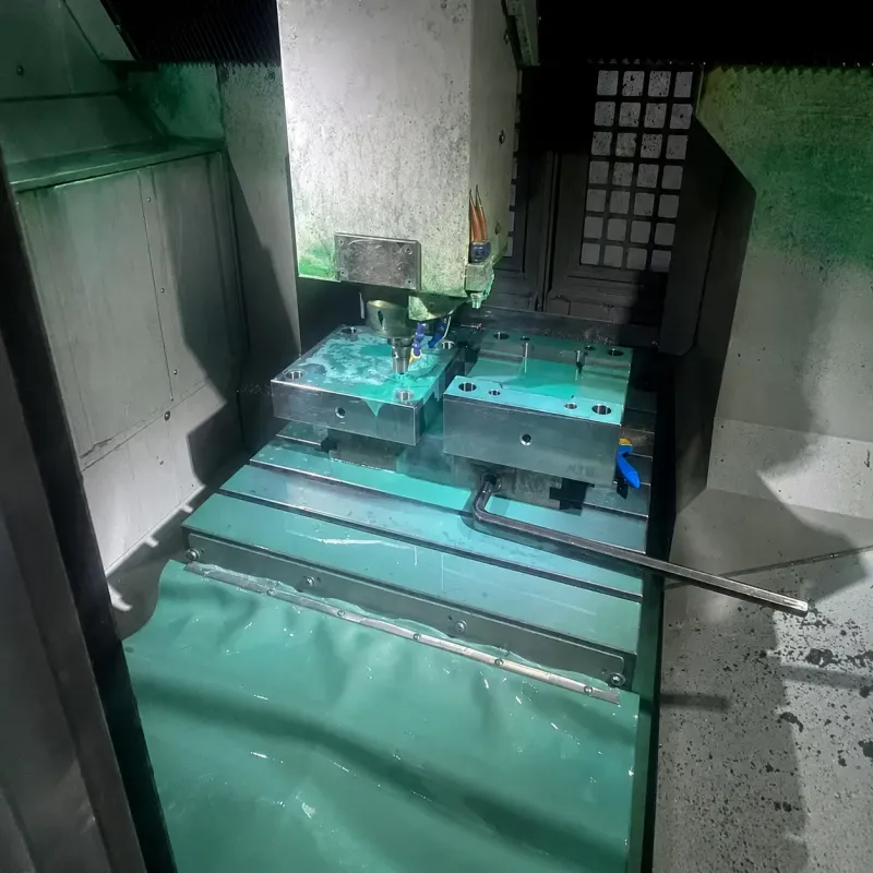
Thin walls also raise cavity pressure. A 1.0 mm wall needs 60-90 MPa of intensification pressure to feed shrinkage in the time before the gate freezes (typical range), against 40-60 MPa on a 3 mm wall. Higher cavity pressure means more clamp tonnage per unit of projected area, stiffer die blocks and tighter shut-offs. Cutting a thin-wall die on the same block design used for a thick housing is the most common mistake we see in DFM review.
Finally, thin walls cool fast and unevenly. The rim, the boss ring and the corner radii hold mass that the flat web does not. That difference drives a temperature spread that bows the part. Thermal design, not gate design, is what keeps a thin housing flat.
Fill Speed and In-Gate Thickness Matching
In-gate thickness and fill speed are one decision, not two. Gate area divided into shot volume gives fill time, and gate area divided into flow rate gives gate velocity. Thin walls need both inside a narrow window: fast enough to beat the freeze-off, slow enough to avoid erosion and air entrapment at the gate land.
Start from the fill time. A 1.2 mm aluminum housing with a 180 mm flow path wants 35-50 ms. Take the shot volume in cubic centimeters and divide by the fill time to get the flow rate. A 320 g aluminum shot at 2.7 g/cm³ is 118 cm³. At 45 ms that is 2,630 cm³/s. Divide by a gate velocity of 55 m/s (550 cm/s) and the gate area comes out near 4.8 cm². A 60 mm wide housing with a 0.8 mm gate gives 0.48 cm², which is ten times too small. That is the trap: thin walls need gate area far larger than a thick-wall die of the same part size.
Gate thickness follows the wall ratio rule with a thin-wall correction. A standard gate runs 40-60% of wall thickness. On a 1.2 mm wall, 40% is 0.48 mm, which is too thin to carry the flow rate without erosion. Practical thin-wall gates run 60-90% of wall thickness, so 0.8-1.1 mm on that housing, with the gate width widened instead. Gate land stays short at 1.0-2.0 mm to keep the pressure drop low, and the land is finished to Ra 0.4-0.8 µm.
| Casting case | Fill time target | In-gate velocity | In-gate thickness | Land length |
|---|---|---|---|---|
| Aluminum, 0.8 mm wall housing | 25-40 ms | 50-80 m/s | 0.6-0.8 mm | 1.0-2.0 mm |
| Aluminum, 1.2 mm wall housing | 35-50 ms | 45-65 m/s | 0.8-1.1 mm | 1.0-2.0 mm |
| Aluminum, 1.5 mm wall housing | 45-70 ms | 40-60 m/s | 0.9-1.3 mm | 1.5-3.0 mm |
| Zinc, 0.5 mm wall housing | 15-25 ms | 45-60 m/s | 0.35-0.5 mm | 0.8-1.5 mm |
| Zinc, 0.8 mm wall housing | 20-40 ms | 40-55 m/s | 0.5-0.75 mm | 1.0-2.0 mm |
← swipe to scroll →
Table note: fill time, gate velocity and gate thickness are typical industry ranges for thin-wall hot chamber and cold chamber dies. Verify against your own shot weight and machine intensification curve before cutting steel.
Two more levers keep a thin-wall gate honest. First, taper the runner from the sprue down to the gate so pressure carries to the last cavity. Second, keep the gate land interchangeable. A bolt-in H13 gate insert costs a fraction of a cavity re-cut when erosion opens the land after 30,000-50,000 shots on aluminum.
Air Entrapment and Vacuum-Assisted Die Casting
A thin wall fills faster than air can leave. At 50 m/s the melt front crosses a 200 mm cavity in under 20 ms, and the gas in front of it has nowhere to go once the wall is 1 mm thick. Trapped gas ends up as 2-5% porosity in the casting, and the defects sit where they hurt most: at the boss ring, in the rim and along the weld lines.
Venting alone cannot keep up on a thin-wall housing. Vent slots at 0.05-0.15 mm depth move a limited volume per unit time, and a 1.0 mm wall reaches the vent before the gas has cleared. Moving the overflows to the last 15% of the fill path buys time, and overflow volume at 25-35% of casting volume is normal on thin-wall work against 15-25% on a standard housing.
Vacuum assist is the reliable answer once gate velocity passes roughly 60 m/s, which is where a 1.2 mm aluminum wall usually lands. A vacuum system pulls the cavity down to 30-100 mbar absolute before the shot, so the gas that remains is thin enough to compress into the metal without forming visible porosity. Porosity typically drops below 1% on a well-sealed system, and the casting becomes weldable and heat-treatable. The cost sits on both sides: a sealed die with O-ring grooves, sealed ejector plates and a vacuum block, plus the machine-side hardware.

Die-side sealing detail decides whether vacuum works. Seal the parting line with a full perimeter groove, seal the ejector plate chamber, and keep total leak area below roughly 1 mm² equivalent. A die that pulls to 200 mbar instead of 60 mbar usually leaks at the ejector plate or through a worn slide clearance. Test the seal on the bench with a vacuum pump before T1, not on the machine at the first shot.
Vent depth still matters with vacuum. Run 0.05-0.10 mm vents at the last fill points, and place them so the vacuum draws through the cavity rather than short-circuiting across it. Blocked vents after 20,000 shots raise cavity pressure and reintroduce porosity, which is why vent cleaning belongs on the daily check sheet.
Die Thermal Balance at 180-250 °C
Die temperature is the single most powerful lever on a thin wall. Aluminum thin-wall dies run 180-250 °C on the cavity surface, with 200-230 °C covering most housing work. Below 180 °C the melt front freezes before the last fill point and cold shuts appear. Above 250 °C soldering starts on cores and ribs, and heat checking accelerates.
The target is not a single number but a balance. Every point of the cavity should reach the last-fill point at the same instant the front arrives. That means the thin web runs cooler than the thick rim, and the boss ring runs cooler still. A die that sits at a uniform 220 °C everywhere will still bow a housing, because the web loses heat 2-3 times faster than the rim and the shrinkage differs across the part.
Hold the spread within ±10 °C across the cavity and ±5 °C across any single functional surface. Measure it with a surface probe or a thermal camera on a steady-state cycle, not on the first 20 shots. Achieving that spread is a matter of channel placement, flow rate and where you spend the heat budget.
Heat balance levers, in order of effect. Cooling channel position and flow rate first, then die temperature controller set point, then the overflow and gate layout, then spray pattern and duration. Spray is the weakest lever and the one most often overused. Heavy spray on a thin web cools it below the fill window while the rim stays hot, which widens the spread the die was designed to close.
Zone control is standard practice on a thin-wall die. Split the circuit into at least three zones: web, rim and boss or slide area. Each zone gets its own controller loop, and each gets its own thermocouple in the return line within 150 mm of the manifold. A single-zone die cannot correct the thermal gradient that bows a housing.
Cooling Layout: 20-30 mm Pitch and Conformal Inserts
Cooling channels behind a thin wall follow a tighter pitch than on a standard housing. Straight drilled lines run on a 20-30 mm center pitch, positioned 12-18 mm below the cavity surface on a 1.2 mm wall. Closer than 20 mm pitch risks thin steel between channels and a short die life under thermal fatigue. Wider than 30 mm pitch leaves a hot band between lines, and the casting bows at that band.
Channel diameter runs 8-12 mm on thin-wall dies. Larger channels carry more flow at lower pressure drop, but they force the channel deeper to keep 2-3 diameters of steel between the channel wall and the cavity. On a 1.2 mm wall with a boss pattern, 10 mm channels at 12-15 mm depth is a practical compromise.
| Feature | Channel pitch | Depth to cavity | Channel dia. | Die temp target |
|---|---|---|---|---|
| Flat web, 1.0-1.2 mm wall | 20-30 mm | 12-18 mm | 8-10 mm | 195-215 °C |
| Boss ring and rib cluster | 15-22 mm | 10-15 mm | 8-10 mm | 180-205 °C |
| Thick rim and flange | 25-35 mm | 15-22 mm | 10-12 mm | 215-245 °C |
| Zinc thin-wall housing | 25-35 mm | 15-20 mm | 8-12 mm | 150-190 °C |
| Slide and core block | 20-25 mm | 10-15 mm | 6-8 mm | 180-220 °C |
← swipe to scroll →
Table note: typical industry ranges for thin-wall aluminum and zinc dies. Depth is measured from the cavity surface to the channel wall, not to the channel centerline.
Where straight drilling cannot reach, use a conformal insert. A boss ring that sits 25 mm inside a deep pocket, or a wall that wraps around a corner, is a candidate. A slide-in beryllium copper or 3D printed insert with a shaped channel holds the pitch through the feature, and it is replaceable when the local steel heat-checks. Our guide to conformal cooling layout covers when the added cost pays back.
Practical layout rules. Keep the channel within 2-3 channel diameters of the cavity on flat webs, run return lines that leave the die hot rather than crossing cold zones, and drill bubblers or baffles into any core that is thinner than 25 mm. A 6 mm bubbler in a fin core pulls 3-5 times the heat of a straight hole of the same diameter. Plug every unused line and record the circuit map on the die drawing, because a swapped inlet and outlet will invert the thermal balance at the first trial.
Ejection Layout and Ejection Force
A thin housing sticks to the core and then collapses when the ejector pushes. Ejection force runs 5-15 kN on a typical housing, spread across 20-60 pins and the runner. Contact pressure, not total force, decides damage: keep it below 8 MPa on aluminum at 200 °C so the pin does not punch into the wall.
Pin area follows from that limit. A 15 kN ejection load at 6 MPa needs 25 cm² of total contact area, which is 40 pins of 8 mm diameter or 20 pins of 12 mm diameter. On a thin housing the answer is usually more pins, not bigger ones: 6-8 mm ejector pins on a 25-40 mm grid, with additional pins under every boss, corner and stiffener. Our ejector pins are available from 3-7 days in H13 and SKD61 for this reason.

Placement rules that avoid distortion. Put pins over the strongest local geometry, never on a bare 1 mm web. Balance the layout around the part centroid so the ejection force passes through the center of mass. Keep the first 5 mm of stroke slow, at 0.5-2 mm/s on a two-stage ejector, then accelerate. Add stripper plates or a knock-out grid on large flat panels, because a housing with 30 pins can still bow if the pins are all inboard of the rim.
Ejection also interacts with draft. A 0.5-1.0 degree draft on a 40 mm deep side wall is enough for aluminum, but a textured or as-cast finish needs 1.5-2.0 degrees. Insufficient draft turns ejection force into a stripping force, and a thin wall strips before it releases. Check draft on every vertical face at DFM stage, not after the first scratched casting.
Side Holes and Cooling Fins: Inserts and Slides
Thin-wall housings carry the features that need moving steel: side holes for screws or connectors, cooling fins 0.8-1.5 mm thick, and snap or shield tabs. Each one is a design decision with a tooling cost attached.
Side holes. A hole on the parting line can be cored by a simple boss on the fixed or moving half. A hole normal to the draw needs a slide or an insert. Cylindrical holes under 6 mm diameter are usually cored by a removable core pin in a slide, while larger holes take an insert or a slide-mounted core. Slots and rectangular cut-outs above 10 mm length need a slide with a locking block, because the core cantilevers under cavity pressure and flexes at 60-90 MPa.
Cooling fins. A fin array is a group of thin blades on the casting, and each blade is a slot of the same width in the die. Blades below 1.0 mm thick are cut in a replaceable insert rather than the cavity block. A separate insert lets the shop cut the fin roots by wire EDM to ±0.02 mm, polish them once, and swap them when the fin tips erode. Hard-cutting fins directly in the block is a false economy: a single chipped blade scraps the whole block.
Slide design for thin parts. Keep slide travel at 5-10 mm beyond the feature depth, use a locking block on the closing side, and feed each slide from a separate cooling circuit. A slide that runs more than 20 °C hotter than the cavity drags and marks the wall. Lubrication channels and a wear plate on the slide seat are standard on any housing that runs above 60 shots per hour.
Coatings: Nitriding and PVD
A thin-wall die runs hotter at the wall than a standard housing die, and hot steel loses hardness. Surface treatment is the cheapest way to buy life back, because it works on the die surface where the damage starts. The two practical options are gas or plasma nitriding and a PVD coating, and they do different jobs.
Nitriding diffuses nitrogen into the steel and forms a case of 0.05-0.15 mm at 900-1,100 HV. It raises resistance to soldering and to the abrasive wear that opens thin gates, and it is applied to the finished cavity at 480-560 °C, well below the tempering temperature of H13 at HRC 44-48. The trade-off is depth control: a case above 0.15 mm on a thin fin or a small core pin makes the surface brittle, and a brittle fin tip chips instead of wearing. Keep case depth at 0.05-0.10 mm on fins and small cores.
PVD coatings such as TiAlN or AlCrN add a 2-6 µm layer at 1,500-3,200 HV by a low-temperature process at 400-500 °C. They resist erosion at the gate land and soldering on hot cores better than nitride alone, and they can be stripped and re-applied. A coating on a cavity face that sees 60-70 m/s metal is worth the added cost on a thin-wall die, particularly at the in-gate and in the last-fill area. Coatings do not replace correct cooling design. A coated die that runs 30 °C too hot still heat-checks.

Where each one pays. Use nitriding on the cavity block, the fin inserts and the slide faces, where soldering and general wear dominate. Use PVD on the gate insert, the sprue bush and the hot cores, where erosion and metal adhesion dominate. A combination is common on a high-volume thin-wall die: nitrided block, coated gate insert, coated core pins. Record the treatment, the case depth and the date on the die drawing. DieStrike builds and heat-treats die blocks to HRC 62 for hard-milled thin-wall inserts, with hardness and case records shipped with the die.
Heat Check Life and Weld Repair
Thin-wall dies die early from thermal fatigue. The wall surface cycles between roughly 200 °C at spray and 550-600 °C at metal contact on every shot, and the thin section cannot carry the heat away as fast as a thick block. Heat checking usually appears at 15,000-40,000 shots on aluminum thin-wall dies (typical), against 30,000-60,000 shots on a standard housing die. Zinc thin-wall dies run far longer, commonly 300,000+ shots.
Judgment criteria. Cracks under 0.1 mm deep are cosmetic and can be polished out. Cracks of 0.1-0.3 mm that appear on a sealing surface or a Class A face need local weld repair before they print into the casting. Cracks over 0.5 mm deep, or any crack that has networked across a boss ring, mean the insert comes out. Continuing past that point produces drag marks, then spalling, then a scrapped block.
Weld repair rules for thin steel. Preheat the block to 300-400 °C before welding, use a matching H13 or 1.2343 filler, and let it cool under an insulating blanket. Peening each pass reduces residual stress. Post-weld, temper at 450-500 °C and re-machine or EDM to size. Welding cold thin steel causes cracking at the weld toe within a few hundred shots, which is why shop temperature and preheat control matter as much as the filler metal. Our die casting tooling service includes weld repair and re-nitriding as part of scheduled maintenance.
Track the interval. Note the shot count at each inspection and each repair on the die record. A die that needed its first weld at 25,000 shots and its second at 40,000 is telling you the thermal layout is wrong, not that the welder is bad. Fix the cooling before ordering a third repair.
Parting Line and Tolerance Control on Thin Sections
Thin walls amplify every geometry error. A 0.05 mm mismatch at the parting line is invisible on a 3 mm wall and clearly visible as a step on a 1.0 mm wall. Two rules keep the line clean: place the parting line on a corner or a feature edge rather than a flat face, and keep the shut-off land wide enough to carry the flash pressure.
Shut-off lands on a thin-wall die run 3-6 mm wide at 5-10 degrees of side angle, with a 0.02-0.05 mm pre-load. Too narrow a land and the die flashes at 60-90 MPa cavity pressure. Too wide and the land does not seat over its whole face, so the die flashes at one end and marks the casting at the other. Grind the land to a flatness of 0.01 mm per 100 mm and check it with bluing at assembly.

Dimensional control on the casting depends on die precision plus shrinkage compensation. Aluminum die casting shrinks 0.4-0.7% depending on alloy and constraint, and a thin wall is more constrained than a thick one, so the same die gives different shrinkage in the web and in the rim. Apply a per-feature shrink factor at design, then verify on the first article with a CMM. DieStrike holds die dimensions to ±0.005 mm and mold part geometry to ±0.002 mm, which leaves the casting tolerance budget to be spent on shrinkage and thermal variation rather than on die error.
Ejection and thermal effects also move dimensions between the first shot and the steady-state shot. Measure the first article after a 30-minute run at production temperature, not on a cold die. A housing that measures 0.06 mm out on a cold die often measures in tolerance once the die reaches 210 °C.
T1 Tryout Judgment Criteria
Thin-wall dies are judged at T1 on five things, and only one of them is dimensional. Run the trial on the production machine at production cycle time, with the die at target temperature. A T1 run on a cold die tells you nothing about fill.
Fill and last-fill location. Confirm the last point of fill sits where the simulation said it would. If it moved, the gate area or the vent path is wrong, and no process tweak fixes it.
Porosity. Cut or X-ray the boss ring, the rim and the last-fill area. Below 1% gas porosity passes for most housing programs. Above 3% in a sealing or structural zone means vacuum sealing, overflow placement or gate velocity needs work.
Thermal map. Shoot the die with a thermal camera on a steady-state cycle. A spread beyond ±10 °C across the cavity is a cooling layout problem, and it will show up as bow in volume production.
Flatness and ejection marks. Measure the housing for bow across the largest face. Marks deeper than 0.05 mm, or a bow above 0.1 mm on a 150 mm face, go back to pin placement and stroke profile.
Die condition. Inspect the gate land, the fin insert roots and the slide faces for erosion or soldering after the trial. Early soldering at 200 shots is a thermal sign, not a steel sign. DFM feedback at DieStrike comes back within 24 hours, and T1 samples run on the production machine with a full dimensional and porosity report.
FAQ
Q1. What is the minimum wall thickness for die casting a housing?
Typical minimums are 0.8 mm for aluminum and 0.5 mm for zinc, and both need vacuum assist and a tight thermal design to run in volume. Practical production housings sit at 1.0-1.5 mm in aluminum and 0.6-0.8 mm in zinc, where the process window stays wide enough for a 100,000+ shot die life.
Q2. How thick should the in-gate be on a thin-wall die?
Run 60-90% of the local wall thickness, so 0.8-1.1 mm on a 1.2 mm aluminum housing, and widen the gate instead of deepening it. Keep the land at 1.0-2.0 mm and finish it to Ra 0.4-0.8 µm. Thin gates erode at 40-80 m/s gate velocity, and an eroded land changes the fill pattern.
Q3. When does vacuum assist pay for itself on a thin-wall housing?
When gate velocity exceeds roughly 60 m/s, when the wall is under 1.2 mm in aluminum, or when the casting needs welding, leak testing at 2-5 bar or T5/T6 heat treatment. Vacuum pulls the cavity to 30-100 mbar and typically cuts porosity below 1%, at 15-30% more die cost plus machine-side hardware.
Q4. What die temperature should a thin-wall aluminum die run?
180-250 °C on the cavity surface, with 200-230 °C covering most housings. Hold the spread within ±10 °C across the cavity and split the circuit into web, rim and slide zones. Below 180 °C expect cold shuts. Above 250 °C soldering and heat checking accelerate.
Q5. How many shots does a thin-wall die casting die last?
Aluminum thin-wall dies typically reach 15,000-40,000 shots before heat checking needs attention, and 100,000-150,000 shots with scheduled weld repair and re-nitriding. Zinc dies run far longer, commonly 300,000+ shots. Cooling at 20-30 mm pitch and a nitrided cavity are the two biggest levers on that number.
The Bottom Line
A thin-wall housing die lives or dies on five numbers: gate area and thickness, cavity temperature balance, cooling pitch at 20-30 mm, ejector pin area and coating depth. Get those right and a 1.0 mm wall runs flat for 100,000+ shots. Miss them and no press setting recovers the lot. DieStrike builds IATF 16949 die casting tooling on 120+ machines to ±0.005 mm die accuracy, with 2-5 week lead times and DFM feedback inside 24 hours.
If your next thin-wall housing program needs a die review before steel is cut, talk to our tooling engineers.
KEEP READING
Related Reading
How to Design Die Casting Gates and Runners: Fill and Venting Rules
Gate velocity, land length, runner taper, overflow volume and vent depth for aluminum and zinc dies.
Read articleArticleH13 vs H11 vs 1.2367: Hot-Work Steel for Die Casting Dies
Which hot-work steel holds hardness and thermal fatigue life on thin-wall cavity inserts.
Read articleArticleZinc vs Aluminum Die Casting: Alloy and Tooling Decision Guide
Alloy choice changes wall thickness limits, die temperature and cooling layout on the same part.
Read articleServiceDie Casting Mold Manufacturing
IATF 16949 die casting tooling built to ±0.005 mm die accuracy with 2-5 week lead times.
Read articleNEXT STEP
Ready to Start Your Mold?
Send us your element dimensions or part numbers — our team responds within 24 hours with pricing and lead time.

Written by
Ray ChanMold Buyer's Guide Author · Precision Mold Manufacturing Specialist. Ray helps global importers, distributors and OEMs source factory-direct molds and mold parts.