
How to Plan Die Casting Die Maintenance: Shot Counts and Heat Checks
Table of Contents
A 1,250 t aluminium cell lost a cavity insert at 38,000 shots. A heat check network behind the gate had grown into a crack 1.4 mm deep, and it opened into the cooling line on the next shift. The die came off the press for eleven days while a replacement insert was cut, hardened and finished. That insert cost more than three years of scheduled maintenance on the same tool. The die had been running a reactive pattern, repairing what broke when it broke.
The scope here is the die itself: damage drivers, the shot count ladder, measurement method and spare strategy.
The Snapshot
- Heat checking appears between 20,000 and 50,000 shots. An aluminium melt at 650 to 700 °C puts a 300 to 400 °C swing into a die face held near 200 °C. The crack network starts at the gate and the hot spots, long before the steel shows wear.
- The PM ladder is counted in shots, not weeks. 5,000 shots for ejector, spray and lubrication checks, 20,000 for slides and cooling circuits, 50,000 to 100,000 for insert replacement and surface renewal.
- Measure before deciding anything. Dye penetrant and replication tape for heat check depth, a portable hardness tester against a 44 to 48 HRC window, gate erosion in 0.1 mm steps, and descaling when cooling flow drops more than 15 percent.
- Aluminium dies run 80,000 to 150,000 shots. A planned 5,000 shot check costs 1 to 2 press hours. Finding the same fault through a machine stop costs 4 to 16 press hours plus 5 to 20 scrapped shots at restart.
Why Die Casting Dies Wear on a Different Clock
An injection mold removes heat from a melt that arrives at 230 to 300 °C. Its steel runs at 60 to 90 °C, and its wear parts come out for abrasion or a dimensional drift rather than a failed cavity face. A die casting die works under a reversed thermal load from the first shot.
Liquid aluminium enters at 650 to 700 °C against a die face at 150 to 220 °C, and the contact lasts 20 to 80 milliseconds. Each shot heats a skin of steel 0.5 to 2 mm deep by 100 to 300 °C. The spray and the cooling lines then pull that skin back down before the next shot.
That cycle is thermal fatigue, and it starts without any defect in the steel. The hot skin wants to expand while the colder steel underneath holds it in place. The surface layer yields in compression and forms a fine crack network at 20,000 to 50,000 shots on an aluminium tool. A zinc tool at 380 to 420 °C runs the same mechanism 5 to 10 times slower.
Hardness follows the same curve. H13 or 1.2343 inserts are delivered at 44 to 48 HRC. After 30,000 to 50,000 shots the surface layer often reads 40 to 42 HRC, because the die has tempered its own skin. A soft face erodes at the gate and solders aluminium faster than a hard one.

The result is a maintenance clock set by shots and thermal load rather than by press hours. Two identical dies can differ by a factor of two in life when one runs a thin wall housing at 45 seconds per shot and the other a 3 kg bracket at 100 seconds. Record the alloy, the shot weight and the die face temperature beside the counter reading.
Damage Drivers in a Hot Die
Seven failure modes account for almost every die casting die repair. Each one has a place where it shows first and a measurement that proves it, and a die that is only checked for flash will hide a growing heat check until the insert cracks.
Thermal fatigue leads the list. It shows as a network of fine cracks on the cavity face, densest at the gate, on boss walls and around core pins. Dye penetrant and a replication tape prove the pattern, and an eddy current probe reads the depth behind it.
Soldering is a temperature problem, not a cleaning problem. Aluminium builds on steel where the die face stays hot and the melt velocity drops, usually on a deep rib or a slow-filling corner. A 0.1 mm build-up already changes the part surface and drags on ejection.
Erosion sits at the gate and at the first runner turn. Gate velocity in aluminium thin wall work runs 40 to 70 m per second, and that jet opens the gate land shot by shot. Wear parts follow: ejector pins and sleeves at 0.02 to 0.05 mm clearance, slide gibs and wear plates, the plunger tip and the shot sleeve bore.
Cooling circuits close the list. Scale and aluminium fines coat the channel wall, and a die that loses 15 percent of its flow runs 10 to 20 °C hotter at the same setpoint. That extra heat feeds straight back into thermal fatigue and soldering.
| Damage driver | Where it shows first | How it is measured | Action threshold |
|---|---|---|---|
| Thermal fatigue | Cavity face at the gate, boss walls and core pin bores | Dye penetrant, replication tape, eddy current depth | Checks deeper than 0.5 mm are welded or ground out |
| Soldering | Deep ribs, slow-filling corners, hot die face areas | Visual under 10x, die face temperature at steady state | A 0.1 mm build-up changes the part surface |
| Gate erosion | Gate land and the first runner turn | Radius gauge or silicone impression in 0.1 mm steps | 0.3 mm shifts the fill pattern, 0.5 mm ends the insert |
| Ejector wear | Pin holes, sleeves and ejector plate bores | Pin gauge on a 0.02 to 0.05 mm clearance, flash check | Clearance above 0.08 mm or flash on a pin boss |
| Slide galling | Slide gibs, wear plates and angle pin bores | Visual scoring, slide force and lubrication record | Scoring plus 0.05 mm of picked-up material |
| Plunger and sleeve wear | Shot sleeve bore, biscuit end, plunger tip | Bore gauge at three points along the sleeve | 0.15 to 0.25 mm of bore wear, or 100,000 to 150,000 shots |
| Cooling circuit loss | Water and oil circuits, worst on the hot cavities | Flow meter per circuit with the die at temperature | Flow loss above 15 percent of the baseline, then descale |
← swipe to scroll →
Table note: thresholds are typical shop values for aluminium and zinc dies in the 800 to 2,500 t range. Set your own limits from the first three inspections on each die.

Two of these drivers hide behind a good part. Over-spray cools the die face below its window, the melt front slows and soldering starts, so the operator answers with more spray. The loop ends with heat checks at 25,000 shots and a gate insert replaced before the first quarter is out.
The Shot Count PM Ladder
A die casting die does not age by the calendar. A tool on a 60 second cycle makes 480 shots in an eight hour shift, and the same tool on a 120 second cycle makes 240. A monthly maintenance slot therefore lands at very different points in the wear curve.
Build the ladder on cumulative shots, then adjust it with duty. A gate velocity above 50 m per second, a wall under 2 mm and a die face above 250 °C each pull the interval in by one step. A heavy bracket with a low cavity count can run one step longer.
The ladder has five rungs. The first three run inside a shift change or a planned break, and only the 100,000 shot rung needs the die on the bench for a full day.
| Interval | On the machine | On the bench | Window |
|---|---|---|---|
| Every shift, 300 to 500 shots | Spray pattern, mix flow, ejector plate lubrication, water flow and temperature, flash at the parting line | Nozzle tips wiped and blown out | 15 minutes, press running |
| 5,000 shots | Ejector pin and sleeve clearance, slide and gib lubrication, gate and runner visual, die face clean and hot spot polish | Spray nozzle strip and clean, O-ring and connector check | 1 to 2 hours |
| 20,000 shots | Cooling circuit flow test and descale, slide strip and wear plate measurement, core pull and angle pin check | Gib re-fit, spray manifold clean, ejector plate bore check | 4 to 8 hours |
| 50,000 shots | Dye penetrant on cavity and gate inserts, hardness at three points, gate erosion in 0.1 mm steps, weld or grind of checks | Re-polish, re-nitride or re-coat when the schedule calls for it | 8 to 16 hours |
| 100,000 shots | Gate insert and sprue spreader replacement, surface renewal by grinding 0.10 to 0.20 mm, plunger tip and shot sleeve replacement | Insert re-cut, die base and parting-line re-fit, first-off dimensional check | 24 to 48 hours |
← swipe to scroll →
Table note: intervals assume aluminium at a 45 to 90 second cycle and a die face held between 150 and 220 °C. Pull every rung in one step for high silicon alloys or thin wall parts.

Surface renewal is the rung most shops skip. Grinding 0.10 to 0.20 mm off the cavity face removes the cracked layer, but it also changes the part wall by the same amount. Keep 0.30 to 0.50 mm of stock allowance at the design stage, and log every grind so the third renewal does not run out of material.
Close each rung with a reading rather than a signature. Flow per circuit, hardness at three points and the gate land radius in 0.1 mm steps give the next inspection a baseline to compare against.
Standard Work Items and Times
Two people cover the 5,000 shot rung inside a shift change if the PM kit sits at the press. The kit for a 1,250 t cell holds spare ejector pins and sleeves at 10 percent of the installed count, spray nozzles, O-rings, a pin gauge set, a radius gauge, a silicone impression kit and a flow meter.
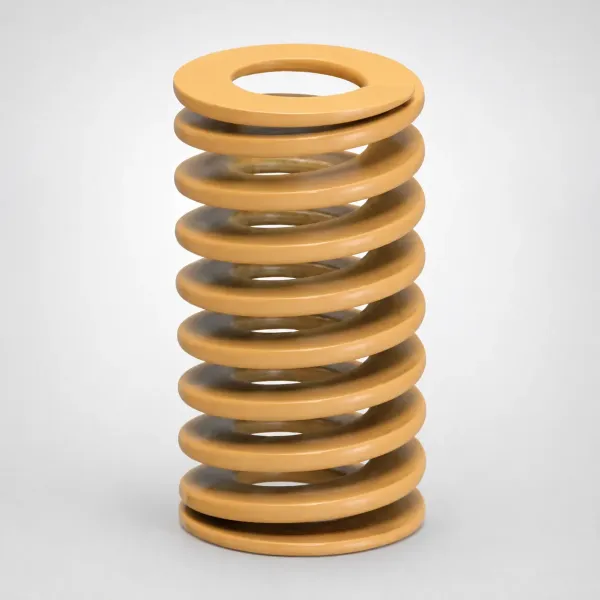
Those times assume a two person crew and a die that comes off the press. Add 2 to 4 hours for a die with more than four slides, plus the lead time for anything ordered: standard components arrive in 3 to 7 days, and a custom insert that needs wire EDM and heat treatment runs 2 to 5 weeks.
Book press time as well as labour. The 20,000 shot rung removes 4 to 8 press hours from the month, so it belongs in the production plan two weeks ahead. A service that gets pushed twice usually gets replaced by a breakdown at the worst point of the quarter.
Measuring Instead of Guessing
Heat check depth decides the die's future. Clean the cavity face with solvent and a nylon brush, then run dye penetrant over the gate, the hot spots and the parting-line land. Examine the result under 5x to 10x magnification, and record check density as cracks per 10 mm of land.
Depth comes from an eddy current probe or a replication tape. A 0.3 mm check is recorded and monitored at the next rung. A 0.5 mm check is ground out or welded. A check that reaches 1.0 mm on the gate land, or a cluster denser than three cracks per 10 mm, ends the gate insert.
Hardness shows whether the steel has anything left to give. Use a portable Leeb or ultrasonic contact impedance probe on a spot polished to Ra 0.8 µm or better, with five readings at the gate land, mid cavity and the parting-line land. The acceptance window for H13 and 1.2343 inserts is 44 to 48 HRC. Below 42 HRC the layer has been overtempered, and any repair sits in soft steel.

Gate erosion is measured in 0.1 mm steps with a radius gauge or a silicone impression. A 0.3 mm growth in the gate land raises local velocity and shifts the fill pattern, which shows up as a cold lap or a fresh flow line. At 0.5 mm, welding the land is a temporary fix at best, because the heat affected zone erodes again in 5,000 to 10,000 shots.
Cooling flow is read with the die at production temperature, and every circuit is compared against its own baseline, because a 6 mm circuit and a 12 mm circuit never match. A circuit reading 4.2 L/min where it read 6.0 L/min has lost 30 percent of its flow, and that side of the die runs 10 to 20 °C hotter. Descale at a 15 percent loss.
Spray volume belongs on the same sheet. A graduated cylinder held at the nozzle for 30 seconds shows a partly blocked nozzle before it moves the thermal balance of one cavity and takes the fill pattern with it.
Write each reading into the tool file beside the shot count. Three inspections produce a wear rate, and a wear rate turns a fixed interval into a decision. When the last two read under half the threshold, move that item down a rung. When one reads above 70 percent, move it up immediately.
Insert Replacement and Spare Strategy
Every die casting die carries parts that are meant to be replaced: the gate insert, the sprue spreader, the cavity inserts, core pins, slide wear plates and gibs, ejector pins and sleeves, the plunger tip and the shot sleeve. Treat them as consumables with a bin number, not as parts nobody wants to touch.
Set spare levels from the shot rate and the lead time. A die running 20,000 shots a month needs one spare gate insert and one sprue spreader on site, with ejector pins and sleeves at 10 percent of the installed count. Standard components ship in 3 to 7 days, while a custom insert with wire EDM and heat treatment runs 2 to 5 weeks. Stock levels and bin locations belong in the mold spare parts inventory, keyed to the die number.
Build spares for interchangeability: same drawing, 0.05 mm of stock on the cavity face, keyed to fit one way only and stamped with the die number. A fitter then swaps a gate insert in 2 to 4 hours and a cavity insert in 6 to 8 hours. Qualify each swap with 5 to 10 shots and a first-off check, and note that die casting die building to ±0.005 mm geometry keeps the spare closing on the same shut-offs as the original. That work and die repair both run under IATF 16949 process control here.
Welding or Replacing a Damaged Insert
Welding repairs work inside clear limits. Cracks up to 1.5 mm deep outside the gate can be micro-welded with H13 or 1.2343 filler. Preheat the area to 300 to 350 °C, hold the interpass temperature under 450 °C, and temper for 2 hours at 540 to 580 °C once the weld is finished.
Recheck hardness after the temper on a polished spot. A repair that reads below 42 HRC erodes or solders within a few thousand shots, and the die comes off the press a second time.
Laser welding holds the heat affected zone to 0.2 to 0.5 mm and suits parting-line edges, ejector pin bosses and small nicks. TIG or stick welding belongs on structural cracks in the die block, never across a cooling channel. Thermal fatigue is cheaper to manage before the cracks start, as covered in heat checking in mold steel.
Three rules end most arguments. Never weld a gate land eroded more than 0.5 mm, because the heat affected zone erodes again in 5,000 to 10,000 shots. Never weld a crack that reaches a cooling circuit, because the die will leak under pressure. A check network across a whole cavity face will not close with weld.
Re-machining is the other route. Grinding 0.10 to 0.20 mm off the cavity face removes the cracked layer and buys another stretch of life, at the cost of wall thickness in every part. Past 0.6 mm of cumulative grind the allowance is gone and a new insert is the only option left.
Die Life Benchmarks by Alloy
Life is set by the melt temperature and by the thermal control around it. The alloy fixes the thermal load, and the maintenance plan decides how much of the available life the die actually delivers.
| Alloy family | Melt temperature | Die life | Gate insert life |
|---|---|---|---|
| Aluminium ADC12 and A380 | 650 to 700 °C | 80,000 to 150,000 shots | 30,000 to 60,000 shots |
| Aluminium A390, high silicon | 680 to 720 °C | 60,000 to 120,000 shots | 20,000 to 40,000 shots |
| Magnesium AZ91D | 620 to 650 °C | 60,000 to 120,000 shots | 20,000 to 40,000 shots |
| Zinc ZAMAK 3 and 5 | 380 to 420 °C | 500,000 to 1,000,000 shots | 200,000 to 400,000 shots |
← swipe to scroll →
Table note: bands assume H13 or 1.2343 inserts at 44 to 48 HRC with the die face held between 150 and 220 °C. Subtract 30 to 40 percent for a face above 280 °C or a gate velocity above 70 m per second.
Zinc dies reach 500,000 shots and beyond because the melt is 250 °C cooler and the thermal swing is small. Aluminium dies reach the top of their band only when the die face holds 150 to 220 °C shot after shot, which is a spray and cooling discipline rather than a steel choice. Cooling layout that keeps the face even is covered in die casting die cooling design.
Records and the Cost Equation
Records are what turn a maintenance plan into a life extension program. The tool file for each die carries the die number, cumulative shots, the last rung completed, and every measured value: hardness, check depth, gate land radius and flow per circuit.
Structure those records in a mold asset register, so a planner can see which of 40 dies sits closest to its next rung and can track shots per cavity between services.
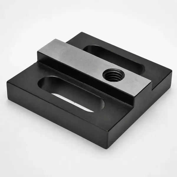
Both sides of the cost equation are real. Skipping the 5,000 shot rung saves 1 to 2 press hours, while the same fault found by a machine stop costs 4 to 16 press hours and 5 to 20 scrapped shots at restart. A cracked cavity block adds a 2 to 5 week insert lead time. Over-maintaining costs less, but a 20,000 shot teardown with nothing due still removes 4 to 8 press hours, so extend intervals on measurement rather than on habit.
Die Casting Die Maintenance FAQ
Q1. How often does a die casting die need maintenance?
Every 5,000 shots for ejector, spray and lubrication checks, 20,000 for slides and cooling circuits, and 50,000 to 100,000 for insert work. A die on a 60 second cycle reaches the first rung in about 10 shifts.
Q2. How deep can heat checks go before an insert is replaced?
Record 0.3 mm checks and monitor them. Grind or weld at 0.5 mm. Replace the gate insert when a check reaches 1.0 mm on the gate land, or when the network passes three cracks per 10 mm.
Q3. Should a worn gate insert be welded or replaced?
Replace it once gate erosion passes 0.5 mm. A weld in the gate region sits in a heat affected zone that erodes again within 5,000 to 10,000 shots.
Q4. What life should an aluminium die casting die deliver?
80,000 to 150,000 shots with a die face held between 150 and 220 °C. Above 280 °C the same die lands at the bottom of that band or below it.
The Bottom Line
Die casting die maintenance is a shot count discipline with four numbers behind it. A 5,000 shot check interval, heat check depth kept under 0.5 mm, hardness held inside a 44 to 48 HRC window, and a die face that stays between 150 and 220 °C. Miss the fourth number and the other three become a repair schedule.
DieStrike builds and maintains die casting dies to IATF 16949 with ±0.005 mm mold accuracy, ±0.002 mm on EDM and jig-ground features, cavity heat treatment to HRC 62 max and more than 120 machines on the floor. Standard components ship in 3 to 7 days, tool lead times run 2 to 5 weeks, and the shop supplies tier-1 programs including TE, Amphenol, Luxshare and Dongshan. Plan the ladder while the die is still being designed, and the tool delivers its full 80,000 to 150,000 shots.
KEEP READING
Related Reading
How to Prevent Heat Checking in Mold Steel
Thermal fatigue in hot-work steel, the surface temperature window that slows it, and the repair thresholds that matter.
Read articleArticleHow to Design Die Casting Die Cooling
Circuit layout, baffles and thermal balance for a die face that has to hold 150 to 220 °C shot after shot.
Read articleArticleHow to Select Mold Steel for Die Casting Dies
H13 and 1.2343 hardness windows, ESR quality and the coating choices that fight soldering and erosion.
Read articleServiceDie Casting Mold Manufacturing
IATF 16949 die building with ±0.005 mm mold accuracy, HRC 62 heat treatment and 2 to 5 week lead times.
Read articleNEXT STEP
Ready to Start Your Mold?
Send us your element dimensions or part numbers — our team responds within 24 hours with pricing and lead time.

Written by
Ray ChanMold Buyer's Guide Author · Precision Mold Manufacturing Specialist. Ray helps global importers, distributors and OEMs source factory-direct molds and mold parts.