
How to Design Roll Forming Dies: Passes, Stands and Tolerance
Table of Contents
A roll set that mis-sizes one flange angle on a 45 m/min line does not produce one bad part. It produces bad parts for eight hours, because the coil keeps feeding and nobody sees the drift until the first offload inspection. On a 600 m batch of 1.5 mm HSLA 340 C-channel, a 3 degree springback error that the schedule never over-bent sends 30 percent of the tonnage to rework, and a schedule redraw plus new top rolls runs two to four weeks. That is a schedule problem, not a machine problem. Roll forming dies fail on pass count, pass order and springback allowance long before they fail on steel.
The scope below covers roll tooling only, and every figure is a typical industry band to confirm against coil data before release.
The Snapshot
- 8 to 14 station pairs per section. A 90 degree C-channel on 1.5 mm HSLA 340 needs 8 to 12 forming and sizing stands, not 4, because high-strength bends break into 2 degree increments.
- Springback returns 2 to 8 degrees on HSLA. A 340 to 700 MPa grade at a 1 mm bend radius rebounds 2 to 8 degrees against 1 to 3 degrees on DC04 mild steel, so the over-bend belongs in the final pass.
- Tool cost of 8,000 to 60,000 USD per section. A roll tooling set lands there, against 150,000 to 600,000 USD for a progressive die making the same constant-section part.
- Plus or minus 0.25 mm on section width. A well-scheduled line holds that figure plus 0.5 degrees on flange angle over a 3 m length, and 60 m/min is where the schedule proves itself.
Where Roll Forming Sits
Roll forming is continuous bending. The strip travels between paired rolls, and each station pair adds a small arc of deformation until the section leaves the last stand fully formed. There is no press stroke, no shut height and no part-by-part cycle. A coil that enters at 0.5 to 3.0 mm gauge exits as a 20 to 250 mm section at line speeds of 3 to 60 m/min, and the part length is set by the cut-off, not by the tool.
That places roll forming between two better-known processes. A draw die pulls a blank into a cavity and thins the wall at the radius, as covered in the deep draw die design guide. A progressive die stamps the part inside the press stroke, so the blank, the carrier and the stroke all cap the geometry. Roll forming caps neither. It forms one meter of channel or three meters with the same roll set, which is why rain gutters, door frames, EV battery rails, racking uprights and cable tray all live on rolls.

The economics follow the geometry. A roll tooling set for a 120 mm wide aluminum-zinc coated C-channel runs 8,000 to 60,000 USD depending on station count and roll material. A progressive die that produces the same constant section, cut and formed at press speed of 5 to 15 strokes per minute, lands at 150,000 to 600,000 USD and still cannot exceed its stroke-limited part length.
The sizing physics also differ. In a press you calculate tonnage and clamp force, the numbers laid out in the press tonnage guide. On a roll line you calculate roll force per station, shaft deflection and drive torque. A 1.5 mm HSLA 340 channel at 45 m/min pulls roughly 3 to 5 kW across the stand group, and the neck of the shaft, not the groove face, carries the failure.
Material and the Bend Allowance Problem
Springback is the first number a roll schedule has to survive. On a 1 mm inside bend radius, DC04 mild steel returns 1 to 3 degrees of the intended angle. HSLA grades from 340 to 700 MPa return 2 to 8 degrees, and the return grows with the strength ratio, the bend angle and the tool radius. A 90 degree flange on 600 MPa steel that never gets an over-bend allowance exits the line at 84 to 88 degrees, and no operator adjustment fixes it.
The correction belongs at the end of the schedule, not the start. Work hardening accumulates pass to pass: every forming stand raises the local yield strength of the flange edge, typically 5 to 15 percent on high-strength grades after five passes. If you over-bend in pass 2 and finish flat in pass 10, the accumulated hardening rebounds the flange back toward the wrong angle. The final sizing or over-bend pass is where the 2 to 8 degree return gets taken out, because that is where the material state is known.

Edge stretch is the second trap. In roll forming the flange edge travels faster than the web, because it wraps around the flange while the web runs straight. That elongation reaches 8 to 15 percent on a 90 degree flange and can pass 20 percent on aggressive schedules. Mild steel with 28 to 34 percent elongation survives. A hard coating or a low-ductility grade cracks at the edge, and any pre-punched hole near the edge stretches into an oval before station 5.
So the 20 percent elongation limit decides hole placement. Holes that must hold position cannot sit on a flange that stretches. Keep in-line holes in the web, away from the bend corners, or punch them after forming on an in-line press or offline, which buys a 0.15 to 0.3 mm hole-to-edge figure instead of a 0.5 to 1.0 mm scatter. The same forming-limit logic that caps a draw depth also caps how much flange a pass can add in one station, and the springback mechanics behind both sit in the springback prevention guide.
Building the Pass Schedule
A pass schedule is built from two rules and one drawing. The rules: no more than 2 degrees of bend increment per pass on high-strength steel, and no more than 15 percent cross-section area growth per pass. Breach the area rule and the strip wrinkles at the flange tip because the edge has nowhere extra to go. Breach the increment rule and springback compounds station to station until the sizing passes cannot recover the angle.
The drawing order runs from the outside in. Start with the flange closest to the strip edge and walk inward, because the edge flanges are the ones that cannot get material from anywhere else. A 3 to 8 pass forming group is normal, followed by 1 to 2 sizing or over-bend passes that set the final angle and the section width. An 8 degree target bend becomes four 2 degree arcs on HSLA, not one 8 degree station.
Here is a typical 12-station schedule for a sample section: a C-channel, 120 mm wide, 1.5 mm HSLA 340, two 40 mm flanges at 90 degrees, aluminum-zinc coated.
| Station | Operation | Left flange angle | Right flange angle | Area growth vs previous pass |
|---|---|---|---|---|
| 1 | Edge bend, left flange | 2 deg | 0 deg | 4 percent |
| 2 | Left flange | 4 deg | 0 deg | 5 percent |
| 3 | Left flange | 6 deg | 0 deg | 5 percent |
| 4 | Edge bend, right flange | 6 deg | 2 deg | 4 percent |
| 5 | Both flanges | 8 deg | 4 deg | 6 percent |
| 6 | Both flanges | 10 deg | 6 deg | 6 percent |
| 7 | Both flanges | 15 deg | 10 deg | 8 percent |
| 8 | Both flanges | 25 deg | 18 deg | 9 percent |
| 9 | Both flanges | 40 deg | 32 deg | 10 percent |
| 10 | Flange close | 62 deg | 55 deg | 12 percent |
| 11 | Forming pass | 85 deg | 80 deg | 14 percent |
| 12 | Sizing and over-bend | 93 deg target | 92 deg target | 3 percent |
← swipe to scroll →
Table note: angles and area growth are worked example values for a 120 mm, 1.5 mm HSLA 340 C-channel with 40 mm flanges. Rebuild the schedule from your own coil test data and springback measurement before cutting steel.
Read the schedule as a shape, not a ladder. The increments start small, grow in the middle passes where the flange is free to rotate, and stop short of 90 degrees at station 11. The last 5 degrees belong to the sizing pass, which also sets section width and carries the 3 degree over-bend that cancels the expected springback. Note that no station crosses 15 percent area growth, and the two edge bends sit at the strip edges first, exactly as the walk-inward rule demands.
Roll Forming Defects That Belong to This Process
Four defects are signatures of roll forming, and each one has a number attached before the tool is cut. Skid marks appear on coated surfaces when the roll face and the coating are mismatched. A hardened roll above HRC 60 running aluminum-zinc coating at high line pressure transfers or scores the coating in visible drag lines. The fixes are a polished or chrome roll face, the correct lubricant film, and a roll gap that does not squeeze the coating to zero.
Oil-canning shows as a visible shallow waviness across a wide flat, typically any web over 80 mm. It comes from slight elongation of the flat inside the forming zone, and it is a geometry defect, not a steel defect, although low-yield-point coils make it worse. A broken profile that separates the flats into smaller formed zones, plus a sizing pass with a light crown, keeps a 120 mm web visually flat to a 1.5 mm bow over 300 mm.

Bow and skew are the asymmetric section tax. A channel is not symmetric, so the flange side of the strip travels a longer path than the web side, and the section tries to curve. Bow is curvature along the length, skew is rotation about it. Both get corrected with idle rolls downstream, not with the forming rolls, and a 2 mm bow over a 3 m length is the correction target for a racking upright.
The fourth signature is edge wave on wide flanges. A 40 mm flange that gains area too fast in one pass ripples at its free edge, and the acceptance band is 0.4 to 0.8 mm of edge wave per meter of formed length. Past that limit, the schedule, not the coil, is the problem: find the station whose area growth crossed 15 percent and split it into two passes.
Roll and Die Construction
Roll material starts with the volume and the surface. 52100 bearing steel, through-hardened to HRC 60 to 62, is the default production roll: it carries the forming load without groove wear and holds a 0.4 to 0.8 micron polish on the groove flank. For cosmetic sections on pre-coated or painted strip, P20 nitrided to a 0.10 to 0.15 mm case at HV 600 to 700 runs the same profile with a lower risk of picking up or skidding the coating, at the cost of shorter hard-layer life.
The roll outer diameter is set by the section width, from 80 to 300 mm. A small OD on a wide section starves the groove of metal at the root, and a large OD on a narrow section wastes blank material and raises inertia at speed. The working rule reads the other way round: pick the largest OD that clears the section and the stand, because OD is bending stiffness.

Shaft size follows deflection, not weight. Shafts run 30 to 70 mm, and the design check is total deflection under 0.01 mm at the forming load measured at the groove line, not at the bearing. A 0.015 mm shaft deflection on a sizing stand prints directly into section width, and no shim adjustment removes it. This is the one number to audit on a supplier's calculation sheet.
Split rolls exist for one reason: closed boxes that cannot be pulled out of a two-piece groove. They are justified above roughly 500,000 parts, because the split line leaves a witness mark on every pass it touches and the insert pockets add 20 to 40 percent to roll cost. Carbide inserts inside a split roll buy coating life on sticky galvanized strip, not surface quality, and the witness mark stays. If the section is open, do not split the roll.
Shaft-to-roll attachment and the balance of the rotating group decide whether the line can even reach its speed rating. At 60 m/min an unbalanced 300 mm roll pair shakes the stand, and vibration marks the surface in a periodic pattern every meter of product. Balance the rotating group, call it out on the drawing, and check the runout of the mounted roll to 0.01 mm at the groove before the first coil.
Line, Stand Set-Up and Roll Gap
Stand pitch is the distance a strip travels between two deformation events, and it runs 300 to 450 mm, adjustable, on most C-line frames. Too tight and the strip between stations cannot straighten its curvature before the next bite, which builds bow. Too wide and the unsupported flange twists between stands, which the schedule did not predict. The pitch also carries the entry and exit loops: a 12-station line at 400 mm pitch needs about 5 m of frame plus decoiler and cut-off.
Roll gap sets the thickness story. Set it to 0.98 to 1.02 times material thickness: a 1.5 mm strip runs a 1.47 to 1.53 mm gap. Below 0.98 the rolls skid the coating and press witness lines into the surface; above 1.02 the section loses size control because the flanges rotate freely instead of being pinned, and width drift passes 0.25 mm fast. Coil thickness tolerance alone, often 0.02 to 0.03 mm on galvanized stock, eats half of that window.
Stands come in three powered classes and one passive class. Side-roll stands guide the strip edge between adjustable idler rollers and carry no groove metal; they live at the entry and between forming groups. Powered stands drive the strip and the forming, and a free-idler stand forms passively, dragged by the section itself, useful for light sizing corrections. Twisted or angled entry stations pre-position the strip edges before station 1, and skipping them is a common cause of edge-wave at station 3.
In-line punching, when the holes sit in the web, adds a press station between forming stands, and the burr rules of any punching operation apply there exactly as on a progressive die: clearance bands, punch wear and slug control are covered in the stamping burr prevention guide. A punch station after the flanges are formed will not hold position, because the strip elongates through the last two stands.
Tolerance Reality at Speed
A well-scheduled line holds plus or minus 0.25 mm on section width and plus or minus 0.5 degrees on flange angle over a 3 m cut length. That is the honest promise. It assumes the pass schedule was built from measured springback, the gap is re-zeroed per coil lot, and the shafts deflect under 0.01 mm. Miss any of the three and the figures double.
Hole position follows the forming order, not the drawing order. Holes punched after forming hold 0.15 to 0.3 mm hole-to-edge, because the strip is already dimensionally stable. The same hole punched in-line before the flanges move stretches into an oval at 0.5 to 1.0 mm scatter, and on a flange it can tear at the 20 percent elongation line. Specify on the section print which holes are in-line and which are post-form, because it changes the station count.
Twist is corrected with stands, not with rolls. Opposed idle stands, set at a small angle against the twist direction, walk the section back flat over 2 to 3 stations. Trying to kill twist inside a forming groove adds edge stretch and re-introduces it downstream once the restraint leaves. A 120 mm channel should leave the last idle stand inside 1 degree of twist per 3 m.
Speed changes the answer. A schedule that holds plus or minus 0.25 mm at 20 m/min can drift 0.1 to 0.2 mm wider at 60 m/min, because thermal growth in the drive line, roll inertia at entry and vibration all load the same gaps. This is why one trial run at 30 to 60 m/min belongs in the acceptance plan, not a slow-line tryout that hides the problem until the production week.
Tooling Cost and Lead Time Drivers
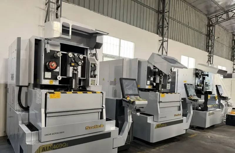
Roll profile machining is the cost center. The groove profile is cut by wire-EDM or 5-axis milling, and the choice moves 2 to 5 working days and a visible slice of the roll price. Wire-EDM wins on hardened 52100 because it cuts HRC 62 directly to a 0.005 mm profile accuracy with no post-machining growth, while 5-axis hard milling wins on complex multi-groove rolls where tool access beats wire reach.
The drawing decides whether the shop can miss by a mile or a micron. GD&T callouts belong on the developed profile curve of the groove, not on the roll blank, because the blank is a stock circle and the curve is the part. A profile curve toleranced to plus or minus 0.01 mm with a stated datum set is buildable; a blank drawing with the curve buried in a dimension string is a rework order waiting to happen.
Surface treatments add days and dollars with intent. Hard chrome plate on cosmetic rolls, 20 to 50 micron, protects P20 and improves release against coated strip. A full polish to 0.4 micron on every groove flank typically adds 3 to 5 working days across a 12-station set. Skip both on a structural racking section and the customer will never know; skip them on a visible door frame and the first article will.
Total tool lead time for a 12-station set runs 2 to 5 weeks when the pass schedule is agreed before steel is cut, and standard components such as shafts, bearings and stand hardware land inside 3 to 7 days on that path. The two killers are an unagreed schedule and a buyer-side change after the profiles are machined. One 2 degree change at station 8 usually re-cuts three rolls, because the downstream angles were built on top of it.
Verification Before Shipment
Roll tooling is verified against the section, not against the roll drawing alone. The first instrument is a profile gauge or first-off template per station: a hard check that the strip leaving station 7 matches the station 7 curve on the schedule drawing, inside 0.1 mm on the profile. Catching a drift at station 7 of 12 costs a shim or a re-cut roll. Catching it at the finished section costs the coil.
Cross-section area gets checked two ways, both cheap. Water displacement on a 300 mm cut sample reads the formed area against the CAD area to within 1 percent, which catches thinning, over-compression and gap errors at once. A laser scan of the section, converted to CAD, does the same job non-contact and documents the whole profile for the tool file.
Twist and bow are measured on a 2 m rail or surface plate, not on a shop floor. Lay the 3 m section on the rail, press one end flat, and read the lift at the free end: under 2 mm of bow and inside 1 degree of twist per 2 m is the pass mark for a structural channel. Then run the trial at 30 to 60 m/min and repeat the same rail check on a line-speed part, because a slow-line first-off that passes at 10 m/min has not yet proved anything about thermal growth or vibration.
Roll condition closes the loop. Hardness on the groove flank must still read HRC 60 to 62 after the trial, and any chrome or nitride layer must be intact at the edges, checked under magnification for the first 50 micron of loss. A production re-check at 100,000 parts confirms hardness and coating are still there before the wear curve bends. Under an IATF 16949 quality system these records, station gauges, area checks, rail readings and the trial speed log, ship with the tool as the acceptance package.
Roll Forming Defect Table
The defects above map to fixed numbers a shop can chase. This table is the troubleshooting order we recommend at the line: check the gap and the schedule before touching the rolls, and check the coil before blaming either.
| Defect | Root cause | Number to check |
|---|---|---|
| Flange angle short | No over-bend in the sizing pass, springback never measured | 2 to 8 deg return on HSLA, over-bend in the last pass |
| Wrinkle at flange tip | Cross-section area growth above 15 percent in one pass | Split the station, keep growth under 15 percent |
| Edge wave on wide flange | Fast area gain on a 40 mm plus flange, no walk-inward order | Limit 0.4 to 0.8 mm per m, re-order the schedule |
| Skid marks on coating | Hard roll face and gap squeezing the coating film to zero | Gap 0.98 to 1.02 x gauge, polish or chrome the flank |
| Section width drift | Shaft deflection over 0.01 mm, or gap re-zero missed per coil | Plus or minus 0.25 mm over 3 m at line speed |
| Oval in-line holes | Hole placed on a flange stretching past 20 percent elongation | Move to web or post-form, 0.15 to 0.3 mm hole-to-edge |
| Bow and skew | Asymmetric section with no downstream idle correction | Under 2 mm bow per 3 m, twist with opposed idlers |
← swipe to scroll →
Table note: thresholds are typical for 0.5 to 3.0 mm steel sections on C-line roll formers. Re-measure springback and elongation from your own coil lot before changing any roll geometry.
Roll Tooling Specification Checklist
Before a roll set is quoted, cut or accepted, the buyer and the shop should be able to tick every line below. The first four items prevent most of the schedule rework described in this article.
- Section CAD plus sample strip. Send the section drawing and a 500 mm sample strip of the shop's own grade, gauge and coating, so springback is measured on real metal, not on a datasheet.
- Pass schedule drawing before steel. Agree the station-by-station schedule, angles and area growth, in writing, before the first profile is cut. This is the single largest schedule risk.
- Roll material and hardness in the PO. 52100 at HRC 60 to 62, or P20 nitrided for cosmetic sections, called out on the purchase order with the hardness verification method.
- Ownership split on the tooling. Agree who owns shafts, bearings and stands versus the rolls. Roll sets are often bought while stands stay with the line.
- OD, shaft and deflection callout. Roll OD 80 to 300 mm matched to section width, shaft 30 to 70 mm, deflection under 0.01 mm at the forming load on the supplier's calculation sheet.
- Gap, pitch and speed window. Roll gap 0.98 to 1.02 x gauge, stand pitch 300 to 450 mm, and the trial scheduled at 30 to 60 m/min, not at 10.
- Tolerance and hole plan. Plus or minus 0.25 mm width, plus or minus 0.5 degrees angle, and every hole marked in-line or post-form with its 0.15 to 0.3 mm callout.
- Acceptance package. Station profile gauges, water-displacement or scan area check, 2 m rail twist and bow readings, post-trial hardness, and the 100,000-part re-check interval in the tool file.
The Bottom Line
Roll forming dies live or die on the pass schedule. Break bends into 2 degree increments on HSLA, keep area growth under 15 percent per pass, walk from the strip edge inward, and put the 2 to 8 degree springback over-bend in the final sizing pass. Then protect the schedule with honest hardware: 52100 rolls at HRC 60 to 62 or nitrided P20 for cosmetic work, shafts that deflect under 0.01 mm, a gap held at 0.98 to 1.02 times gauge, and one trial run at 30 to 60 m/min before anyone calls the tool finished.
The commercial case is as clear as the physics. A tool set at 8,000 to 60,000 USD with unlimited part length beats a 150,000 to 600,000 USD progressive die for any constant section, as long as the section holds plus or minus 0.25 mm width and plus or minus 0.5 degrees over 3 m at speed. DieStrike makes roll and stamping die tooling under IATF 16949, with plus or minus 0.005 mm machining accuracy, plus or minus 0.002 mm on EDM and jig grinding, HRC 62 heat treatment, 120+ machines, standard components in 3 to 7 days and tool lead times of 2 to 5 weeks, with tier-1 references including TE, Amphenol, Luxshare and Dongshan. Send the section CAD, a 500 mm sample strip and the volume target through stamping die manufacturing, and the shop returns a pass schedule drawing before steel is cut.
KEEP READING
Related Reading
How to Prevent Springback in Stamping Dies
Springback returns of 2 to 8 degrees on high-strength steel and the correction tactics that hold the angle.
Read articleArticleHow to Design Deep Draw Dies
Where cup forming works and why a constant section part belongs on rolls instead of a draw die.
Read articleArticleHow to Prevent Stamping Burr
Punch clearance bands and regrind triggers that keep an in-line punching station clean.
Read articleServiceStamping Die Manufacturing
IATF 16949 die and roll tooling with plus or minus 0.005 mm accuracy and 2 to 5 week lead times.
Read articleNEXT STEP
Ready to Start Your Mold?
Send us your element dimensions or part numbers — our team responds within 24 hours with pricing and lead time.

Written by
Ray ChanMold Buyer's Guide Author · Precision Mold Manufacturing Specialist. Ray helps global importers, distributors and OEMs source factory-direct molds and mold parts.