
How to Prevent Springback in Stamping Dies: Compensation Methods
Table of Contents
A 90 degree flange on a 1.5 mm DP780 bracket measured 83.6 degrees after unload on its first try. That 6.4 degree gap cost the program nine days of shim changes on the form station. Springback is elastic recovery, so the die face never equals the part face. The gap gets paid in die geometry, press settings or both, and this article shows which lever to pull for a given grade and thickness.
Scope is air and wipe bends on 0.5 to 3 mm carbon, stainless and advanced high-strength sheet.
The Snapshot
- Recovery scales with strength. Sheet above 590 MPa recovers 5 to 15 degrees on an air bend, while DC01 mild steel at 0.8 to 2.0 mm recovers 0.5 to 2 degrees on the same radius.
- Shim in small steps. A trial-shim loop moves 0.02 to 0.05 mm per step, and 2 to 4 steps close a typical 3 to 6 degree angle gap.
- Coining buys the last degrees. A bottoming pass at 5 to 20 percent extra tonnage sets 1 to 3 mm sheet by plastic flow instead of elastic recovery.
- Hardware holds the result. Binder pressure of 10 to 25 MPa on the flange, a punch radius of 1 to 2t minimum and a 0.5 to 3 s hold at bottom dead centre keep the angle stable in production.
What Springback Costs on the Line
Springback is the elastic half of every bend coming back when the punch leaves. The inner fibre yields in compression and the outer fibre stretches, while the elastic core recovers the moment the load drops. The size of that recovery is a property of the coil, not an opinion about the die.
The cost lands in three places. Tryout on an uncompensated form die runs 2 to 6 extra weeks. Press time for a shim trial costs 100 to 300 dollars an hour at many shops. A 6 degree miss on a structural bracket is scrap, because assembly cannot pull a stiff flange home.
Two families of fix exist. The die face can be cut, shimmed or coined to a compensated angle. The process can also be set to restrain the strip so it springs less when the punch releases. The design-side theory belongs to the springback compensation overview. This page stays on the shop floor, where the levers are measurement, shim steps, coining and restraint.
Price the fix before the first try. A die face cut from a measured angle map costs machining hours once. A die corrected after the tryout costs those hours plus press time plus schedule.
Measure the Recovery Before You Cut Steel
Measure free-bend recovery on parts from the real coil. Run 20 to 30 parts at production speed, let them cool at least 10 minutes, and read the angle at three spots per bend: both ends and the centre.
A CMM gives the tightest number, and the report format follows the same discipline as any dimensional check. A digital protractor and a height gauge on a surface plate hold about ±0.1 degrees, which is enough to decide a 2 degree correction. Reading a CMM report for form features means checking the reporting fixture, the part temperature and the datum scheme before trusting the angle.
Control three variables during the measurement. Strip direction relative to the rolling direction, the coil lot, and the die temperature. A part measured 3 minutes off the press reads 0.3 to 0.8 degrees different from the same part after 10 minutes, which is why the cooling rule matters.
Log every result against a golden sample part. Keep the golden sample in the tool file, measured on the same fixture, and re-measure it whenever the gauge or the operator changes. A drift in the golden sample number means the measurement system moved, not the parts.

Measure the die angle under load whenever the press has a load monitor or a cushion readout. The gap between the loaded die angle and the free part angle is the recovery the die has to absorb. On a 1.5 mm DP780 flange that gap often runs 5 to 7 degrees, and it belongs in the die file next to the shim map.
Springback by Material Grade and Thickness
Recovery is set by the ratio of yield strength to elastic modulus, the radius to thickness ratio, and the restraint on the flange. Yield strength spans 140 to 1,500 MPa across common sheet grades while the elastic modulus stays near 205 to 210 GPa. That is why the grade name predicts the shape of the problem and the coil certificate predicts its size.
The bands below are typical air-bend values at a punch radius of three times the sheet thickness. Use them to budget the first try, then replace them with the measured number from your own coil.
| Material and thickness band | Typical recovery at a radius of 3t | First compensation move | Watch-out |
|---|---|---|---|
| DC01 mild, 0.8 to 2.0 mm | 0.5 to 2 degrees | Over-bend 1 to 2 degrees | Rarely critical, hold one iteration in the plan |
| HSLA 340 to 420, 1.0 to 3.0 mm | 2 to 4 degrees | Over-bend plus radius undercut | Yield spread between lots up to 40 MPa |
| DP590 and DP780, 1.0 to 2.5 mm | 5 to 10 degrees | Predicted over-bend plus a planned shim loop | Recovery varies with bend direction to the rolling direction |
| DP980 to DP1180, 0.7 to 2.0 mm | 8 to 14 degrees | Coining or beads on top of over-bend | Edge cracking limits the inside radius to 1 to 1.5t |
| Martensitic MS1300 to MS1500, 0.7 to 1.6 mm | 10 to 15 degrees | Two-stage re-form, not a single bottoming strike | Geometry alone cannot absorb the recovery |
| Stainless 304, 0.5 to 2.0 mm | 4 to 8 degrees | Over-bend plus binder tension | Work hardening shifts recovery across the stroke set |
| Aluminium 5052 H32 and 6061 T4, 1.0 to 3.0 mm | 2 to 6 degrees | Over-bend, with a wider tolerance budget | A lower elastic modulus raises recovery per unit of yield |
← swipe to scroll →
Table note: recovery bands are typical published and industry values for an air bend at a punch radius of three times sheet thickness. Measure the actual coil lot before cutting compensated steel, and treat every number here as a starting budget rather than a guarantee.
Read the table with the radius ratio in hand. A 1.0 mm DP980 bracket with short rigid flanges may recover only 3 to 4 degrees because the flange cannot move. A 0.8 mm DP980 member 600 mm long springs over the whole span, and no single coining stroke reaches the middle of it.
Over-Bend and Bend Allowance Correction
Over-bend is the first and cheapest compensation. Cut the die face at the target angle plus the measured recovery, so a die aimed at 90 degrees with a 6 degree recovery is cut at 84 degrees. The part then unloads to 90 degrees in the free state.
Correct the bend allowance at the same time. The developed blank length follows BA = (pi/180) x A x (R + K x t). Here A is the bend angle in degrees, R the inside radius, t the thickness and K the neutral-axis factor. K runs near 0.33 for a tight radius around 1t and 0.42 to 0.50 above 4t. A 0.05 error in K on a 90 degree bend in 2 mm sheet moves the blank edge by roughly 0.1 to 0.3 mm.
Watch the outer fibre when you over-bend. Cutting an extra 6 degrees into the punch raises the outer-fibre strain, and on DP980 the forming limit is already close. If the compensated angle pushes strain past the limit, take the recovery out with a bead or a second form stage instead of more angle.
Each over-bend correction removes 60 to 80 percent of the residual. Two to four iterations from the first try to a part at print is a normal launch when the first guess is measured.
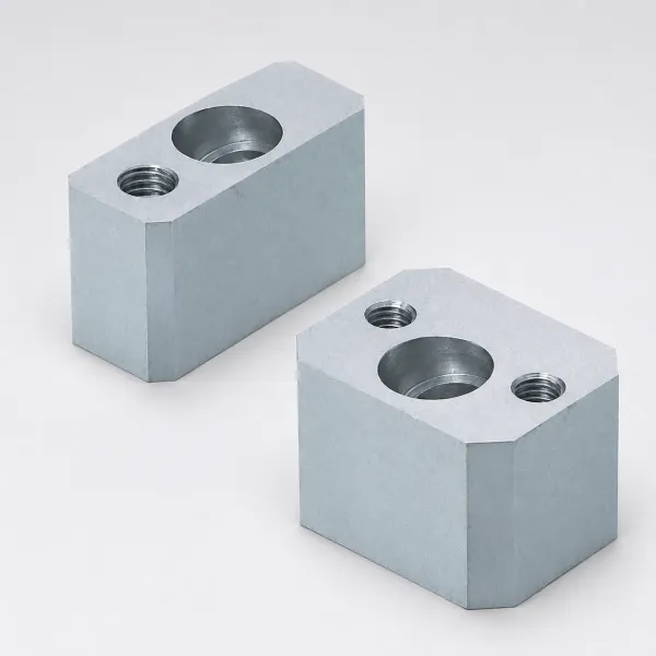
Cut the compensation into the die steel, not into a shim stack that travels. Machine the compensated angle into the punch or the insert and record the nominal on the die drawing. A shim stack is a trial tool, and it is not production hardware.
The Trial-Shim Loop at the Press
A shim loop moves the die face in small increments and re-measures after every step. Open the die, place shims under the form insert or behind the punch, close and run 10 to 20 parts, then measure the angle after a 10 minute cool. A step size of 0.02 to 0.05 mm per shim keeps the loop controlled.
Translate that step into degrees before you stack shims. A 0.05 mm shim placed 50 mm behind the bend line changes the flange angle by about 0.06 degrees. Five stacked shims therefore buy about 0.3 degrees, which is enough to judge direction but not enough to close a 6 degree gap on its own.
When a shim stack passes 0.3 to 0.5 mm, stop shimming and cut the die. A stack that deep changes the shut height, bends the insert, and loads the guide pins off axis. Weld and regrind the radius, or swap in a re-machined insert, and then restart the loop from the new nominal.
Keep a shim map for every station. Record the shim position, the thickness, the measured angle before and after, and the shot count at which the reading was taken. The map is what the next crew inherits, and it tells a die maker which station carries the error.
Never ship a die with a loose shim stack in a production station. Convert the compensated height into a ground insert, a bolted plate or a hardened spacer with dowel location. Update the drawing as well, so the geometry is reproducible after the next regrind instead of depending on a stack of loose sheets.
The Coining Stroke and Hold Time at BDC
Coining sets the bend by plastic volume displacement instead of elastic recovery. A bottoming pass at 5 to 20 percent above the normal forming tonnage presses the sheet against the die face and re-trims the angle. The method suits 1 to 3 mm sheet with short stiff flanges, and it commonly pulls recovery under 1 degree.
Check the press before the tonnage goes up. Forming force plus a 20 percent coining margin has to sit inside the press capacity at the working stroke, and the die members have to carry the same load. A 20 percent increase on a 300 ton forming load adds 60 tons, which is cheap on a 600 ton press and impossible on a 350 ton one.
Hold the load at bottom dead centre. A dwell of 0.5 to 3 s lets the material relax under full pressure, and it removes 1 to 3 degrees on many air bends. A mechanical press holds the bottom only for the crank dwell, while a servo press can hold the ram still. The bump-and-dwell stroke on a servo press is a direct springback lever, and the comparison between the two machine types is covered in the servo press versus mechanical press article.
Accept the trade-offs. Coining leaves a strike witness on the flange, so it does not suit an exposed class A face. It also raises die stress, adds press wear and lengthens the cycle. Use it on short flanges that carry load, and use over-bend plus beads on long cosmetic panels.
Where single-strike coining cannot reach the recovery, plan a multi-stage re-form instead. Martensitic grades above 1,300 MPa recover so far that two forming stations, each taking part of the angle, hold tolerance better than one bottoming strike.
Restraint Levers: Draw Beads and Blank Holder Pressure
Restraint removes springback before it happens. A flange held under tension through the binder cannot recover the full elastic strain when the punch retracts, so the measured angle sits closer to the die angle. The lever is the combination of binder pressure and draw bead resistance.
Set binder pressure from the flange area, not from habit. Target 10 to 25 MPa across the flange contact. A 300 x 200 mm flange is 60,000 mm2, or 0.06 m2, and 15 MPa on that area needs about 900 kN or 92 tonnes of binder force.
Tune the bead instead of adding pressure. A bead height of 3 to 6 mm with a bead radius of 1.5 to 3 mm adds a controlled restraining force without crushing the flange. Change one variable per trial, bead radius in 0.2 to 0.5 mm steps or bead height in 0.2 mm steps, and re-measure after each change. The mechanics of bead geometry and binder design are covered in the draw beads and binders article.
Watch two failure modes while you tune. Excess restraint tears the flange on the stretch side, and hard bead contact damages a galvannealed or painted coating. A bead that lifts the coating shows up later as corrosion, so check the flange surface after every bead change.

Log bead and binder settings with the angle results. The setting that produced a good part has to survive a coil change, so record it against the coil lot and the lubricant batch.
Geometry Levers: Punch Radius and Radius-to-Thickness
Geometry decides how much recovery the die has to absorb. Springback is worst when the punch radius falls below about three times the sheet thickness. A tight radius stores a larger elastic component at the bend, so the angle moves further when the load releases.
Keep the punch radius at 1 to 2t minimum for formability. Below 1t the outer fibre strains past the forming limit on advanced high-strength sheet, and a crack replaces the angle as the primary defect.
Change the geometry when the numbers say so. Recovery above 8 to 10 degrees that shims and coining cannot absorb calls for a design move. Add a stiffening bead or a step in the flange, convert the bend into a wipe form with a controlled radius, or shorten the unsupported flange length. Each of these raises the section stiffness that resists elastic recovery.
Ask the customer before the geometry moves. A bead or a rib on a structural member changes the part. It belongs in a DFM conversation at the drawing stage, not in a die rework after the first try.
The FEA to Shop Compensation Loop
Simulation predicts the recovery before the die is cut, and the shop verifies it. A forming model with a calibrated material card outputs a springback angle map across the part. An auto-compensation tool reads that map and morphs the die surface in the opposite direction, so the die carries the recovery and the part lands at print.
Expect 2 to 5 cycles before the surface settles. Each cycle cuts 0.1 to 0.5 mm off the die face in the compensation direction, and each physical try re-measures the residual. An uncalibrated model using handbook data misses the residual by 20 to 40 percent, while a model tuned on one physical try lands within about 5 to 15 percent.
Cut about 80 to 85 percent of the predicted compensation into the first die. That leaves a small residual for the first try to measure instead of a structural miss, and it keeps a margin on the side where the material is more variable. Update the model with the measured angle before the next cycle, not after the tryout week is over.
Machine the compensated surface to tolerance. Form features on the die face sit at ±0.005 mm on a precision build, with ±0.002 mm on EDM and jig-ground features. Heat treatment to HRC 62 keeps the surface where it was cut. A compensated angle that moves in service is no compensation at all. The stamping die manufacturing service covers how the loop is planned at DFM and carried through the tryout.
Keep the compensation report with the die. The angle map, the cycle history, the cut depth per cycle and the final measured angles form the record an IATF 16949 audit asks to see.
Choosing the Compensation Method
Pick the method by the size of the gap, the sheet thickness and the geometry. A small residual in the first degree band belongs to over-bend. A gap of 3 to 6 degrees on a short flange responds to coining. Long members and draw flanges respond to restraint. Recovery above 8 to 10 degrees that survives all three is a geometry problem.
| Method | What it changes | Typical range | Best use | Limits |
|---|---|---|---|---|
| Over-bend the die face | Die angle | 1 to 8 degrees | First move on almost every air bend | Needs a new cut for each change |
| Shim the form insert | Die height | 0.02 to 0.05 mm per step | Trial loop and small residuals | A stack past 0.3 to 0.5 mm is not production hardware |
| Coin at bottom dead centre | Tonnage at the bottom | 5 to 20 percent extra | Short stiff flanges in 1 to 3 mm sheet | Strike witness and press capacity |
| Hold or bump-dwell | Pressure at the bottom | 0.5 to 3 s | Servo presses and short stiff bends | Cycle time, and a mechanical press has no true dwell |
| Draw bead and binder tuning | Restraint tension | 10 to 25 MPa binder | Draw flanges and long members | Tearing and coating damage |
| Geometry change | Part and die geometry | Recovery above 8 to 10 degrees | Any grade where the other levers run out | Needs customer approval at DFM |
← swipe to scroll →
Table note: method ranges are typical shop values for carbon, stainless and advanced high-strength sheet from 0.5 to 3 mm. Confirm the press capacity and the allowed flange surface before a coining or dwell change is written into the process sheet.
Sequence the levers from cheapest to most expensive. Measure first, over-bend second, shim to confirm, then add coining or restraint, and change geometry only when the measured recovery proves the other levers cannot reach the tolerance.
Springback Compensation FAQ
Q1. How much springback should I budget for DP780?
Expect 5 to 10 degrees on an air bend at a punch radius of three times the sheet thickness. Check the coil certificate as well, because lot yield can move the number by 40 MPa.
Q2. Why measure 10 minutes after the part leaves the press?
Temperature changes the reading. A part measured 3 minutes off the press can read 0.3 to 0.8 degrees different from the same part after 10 minutes. That error is the same size as one shim step. Cool, then measure at three spots per bend.
Q3. How large should a shim step be?
0.02 to 0.05 mm per step. A 0.05 mm shim placed 50 mm behind the bend line changes the flange angle by about 0.06 degrees. A 3 to 6 degree gap needs 2 to 4 steps at that rate. A stack past 0.3 to 0.5 mm should be cut into the die instead.
Q4. Does coining always remove springback?
No. Coining works when the press has 5 to 20 percent of extra tonnage available at the bottom and the flange can accept a strike witness. On a class A panel or a press running at capacity, over-bend and bead restraint carry the correction instead.
Q5. When is it time to change the part geometry?
Change the geometry when recovery exceeds 8 to 10 degrees after all four levers have been applied. Change it also when the inside radius needed for compensation puts the outer fibre past the forming limit. At that point the fix belongs on the drawing.
Q6. How many FEA iterations are normal?
Two to 5 auto-compensation cycles, each removing 0.1 to 0.5 mm from the die face. A model calibrated on one physical try lands within 5 to 15 percent of the measured angle. An uncalibrated model misses by 20 to 40 percent and wastes the tryout week.
The Bottom Line
Springback control is a measurement loop with a hardware decision at the end. Measure the recovery on the real coil at three spots per bend and budget the grade band. Then compensate in the cheapest order: over-bend first, shim to confirm, then coining or restraint on stiff short flanges. Change geometry only when the numbers say the die cannot reach tolerance.
The numbers that hold a program on schedule are small. Shim steps run 0.02 to 0.05 mm, coining adds 5 to 20 percent tonnage and binder pressure runs 10 to 25 MPa. Punch radius stays at 1 to 2t, the bottom dwell at 0.5 to 3 s, and the auto-compensation loop at 2 to 5 cycles, each pass taking 0.1 to 0.5 mm off the die face.
DieStrike builds stamping dies and precision tooling to IATF 16949. Form features hold ±0.005 mm, EDM and jig-ground details hold ±0.002 mm, and heat treatment runs to HRC 62 across 120+ machines. Die lead time runs 2 to 5 weeks, standard components ship in 3 to 7 days, and the reference list includes tier-1 programs with TE, Amphenol, Luxshare and Dongshan. Plan the compensation loop at DFM and the tryout room stops being a repair shop.
KEEP READING
Related Reading
How to Design a Progressive Die Layout
Station sequencing, carrier design and where a form station earns its pitch before the coil is fed.
Read articleArticleHow to Design for High Strength Steel Stamping
Which grades crack, which grades spring past 10 degrees, and what the part must concede at DFM.
Read articleArticleHow to Read a CMM Report
Datum schemes, probing strategy and the form-feature numbers that make an angle reading trustworthy.
Read articleServiceStamping Die Manufacturing
IATF 16949 die building with springback compensation planning, 2 to 5 week lead times and 120+ machines.
Read articleIndustryAutomotive Stamping Dies and Tooling
Draw dies, progressive dies and trim tooling for body panels, seats, underbody and battery structures.
Read articleNEXT STEP
Ready to Start Your Mold?
Send us your element dimensions or part numbers — our team responds within 24 hours with pricing and lead time.

Written by
Ray ChanMold Buyer's Guide Author · Precision Mold Manufacturing Specialist. Ray helps global importers, distributors and OEMs source factory-direct molds and mold parts.