
How to Design Draw Beads and Binders: Restraining Material Flow
Table of Contents
A 1.4 mm mild steel floor pan tore at both punch radii on the first tryout panel. Bead penetration was set at 4.5 mm in a 5 mm bead and the binder ran at 4.2 MPa. The flange fed so little material that the wall thinned to 0.62 mm at the radius, against a 0.98 mm print minimum. Cutting the inserts 0.8 mm shallower and dropping the cushion to 2.6 MPa stopped the tear. The fix still cost 11 days of schedule, and the binder and beads set 60 to 80 percent of the material reaching the cavity.
This guide covers the numbers behind that control: bead geometry and type, bead placement, cushion pressure, tuning with shims, forming simulation, the defects each setting produces, and the wear intervals that hold restraining force inside its window.
The Snapshot
- Beads set 60 to 80 percent of material inflow. A full bead adds 0.2 to 0.6 kN of restraining force per mm of bead length, so a 300 mm bead carries 60 to 180 kN against a 1,500 kN cushion.
- Bead geometry lives in a narrow window. Height 3 to 8 mm, bead radius 3 to 6 mm, gap of sheet thickness plus 0.03 to 0.10 mm, penetration 2 to 4 mm and an addendum radius of R8 to R15.
- Penetration is the sensitive variable. Restraining force changes by 3 to 10 times the change in penetration, so penetration is set within 0.1 mm and confirmed in simulation before any insert is hardened.
- Binder pressure, not force, is the setpoint. A double action cushion at 20 to 40 percent of press capacity delivers 1.5 to 4 MPa on the blank face, rising with blank thickness and coating.
- Bead inserts are consumables. A worn bead loses 10 to 25 percent of its restraining force, so bead height and radius are checked every 20,000 to 50,000 hits.
What the Binder and the Beads Control
In a draw die the punch and the cavity set the shape of the panel. The binder and the beads set how much sheet is allowed to arrive, and how fast. The binder is the flat steel ring that pinches the blank against the die face. A draw bead is a rib standing proud of that binder which forces the sheet to bend, drag and unbend as the flange passes over it.
The split between the two systems is measurable. Bead geometry and binder pressure together set 60 to 80 percent of material inflow on an automotive panel. The punch radius, the die radius and lubrication set the remaining 20 to 40 percent through bending and friction. When a panel tears or wrinkles, the bead and the binder are the first two items to check, because both can be changed without touching the cavity.

Restraining force is the number that matters. Drag a strip of 1.2 mm mild steel across a full bead and the resistance lands at 0.2 to 0.6 kN for every mm of bead length. A 300 mm bead on the draw ring therefore adds 60 to 180 kN of drag to a cushion rated at 1,500 kN, which is 4 to 12 percent of cushion capacity from a single rib.
That drag buys control. Steel entering the cavity at a controlled rate stretches evenly across the punch face and reaches the corners without over-thinning. Steel entering freely builds a slack flange, then buckles into a wrinkle that no binder pressure can iron out at the bottom of the stroke.
Three forces work on the flange at the same time: binder pressure holding it down, bead drag resisting movement, and the punch pulling material toward the cavity. Size that triad and the panel forms. Set any one of the three outside its window and the die produces tearing, wrinkling or a loose panel with oil-canning around the trim line.
The bead is also the cheapest adjustment in the tool. Moving 0.1 mm of penetration on a loose insert costs a press stop, while changing a punch radius costs a weld repair and a re-spot. That is why a forming review targets the bead first and the cavity last.
Bead Geometry: Height, Radius, Gap and Penetration
Bead geometry is defined by five numbers. Height is how far the rib stands above the binder face, typically 3 to 8 mm. Bead radius is the corner radius of the rib, normally 3 to 6 mm.
Gap is the clearance between the bead and its matching groove, equal to sheet thickness plus 0.03 to 0.10 mm. Penetration is how far the bead presses into that groove, usually 2 to 4 mm. Addendum radius is the blend where the binder meets the die entry, and it runs R8 to R15.
Height and radius are linked. A taller bead on a small radius drags harder, and it also work-hardens the flange more because the steel bends through a tighter arc twice per pass. On 1.2 mm mild steel a 4 mm bead with an R5 radius and 3 mm penetration sits in the middle of the useful band. On 0.7 mm high strength steel at 780 MPa the same rib over-restrains the flange, so height drops to 3 mm and the radius opens to R6.

Gap is a clearance, not a fit. At sheet thickness plus 0.03 mm the bead grips and drags the sheet. Above sheet thickness plus 0.15 mm the bead stops restraining the flange and becomes a forming rib that only stiffens it. Below sheet thickness the bead clamps and marks the panel, and on coated material it strips the zinc or the aluminium layer at the contact line.
Penetration is the dimension a die maker tunes during tryout, and it is the most sensitive in the tool. Published bead data puts the change in restraining force at 3 to 10 times the change in penetration across the useful range. A 0.5 mm move in penetration can double the drag a bead applies, which is why penetration is held within 0.1 mm and checked in a forming simulation before any insert is hardened.
| Sheet and thickness | Bead height | Bead radius | Gap | Penetration |
|---|---|---|---|---|
| 0.7 to 0.9 mm mild steel | 3 to 4 mm | R3 to R4 | t + 0.04 mm | 2.0 to 2.5 mm |
| 1.0 to 1.5 mm mild steel | 4 to 5 mm | R5 to R6 | t + 0.05 mm | 2.5 to 3.5 mm |
| 1.0 to 1.5 mm AHSS at 590 to 780 MPa | 3 to 4 mm | R5 to R6 | t + 0.06 mm | 2.0 to 3.0 mm |
| 1.6 to 2.5 mm mild steel | 5 to 8 mm | R6 | t + 0.08 mm | 3.0 to 4.0 mm |
| 0.8 to 1.2 mm aluminium 5182 | 3 to 4 mm | R5 | t + 0.06 mm | 2.0 to 2.5 mm |
| 1.2 mm hot-dip galvanized steel | 4 mm | R5 to R6 | t + 0.10 mm | 2.5 mm |
Table note: t is the nominal sheet thickness. Bead heights and penetrations are typical starting values for a single full bead on a production draw die. Confirm against the material certificate and the forming simulation before the bead inserts are cut.
← swipe to scroll →
Bead Types and Their Restraining Force
Four bead forms cover most panel work, and each applies a different amount of drag. A full bead is a complete rib that the sheet wraps on both sides, and it produces the highest drag of the working shapes. A half bead is a rib the sheet bends over once, so drag lands at roughly 40 to 60 percent of a full bead. A step bead is a shallow step with a large radius, used where the flange needs stiffness with light restraint. A lock bead is a full bead placed where the blank must not move at all, and it is typically 30 to 50 percent deeper than a working bead.
| Bead type | Restraining force | Key dimension | Typical use |
|---|---|---|---|
| Full bead, single | 0.2 to 0.6 kN per mm | Height 4 to 5 mm, R5 | Roof, hood, door inner and outer panels |
| Full bead, double | 0.5 to 1.2 kN per mm | Two ribs 15 to 20 mm apart | Deep parts with a long flange and high stretch |
| Half bead | 0.1 to 0.3 kN per mm | Height 3 to 4 mm, R5 to R6 | Flanges needing stiffness with light restraint |
| Step bead | 0.05 to 0.15 kN per mm | Height 1.5 to 3 mm, R8 to R10 | Floor parts and inner panels, mild restraint |
| Lock bead | 1.0 to 2.0 kN per mm | Height 6 to 8 mm, penetration 4 mm | Draw ring and trim edges where the blank is held |
Table note: force bands are typical values per mm of bead length on 1.0 to 1.5 mm mild steel. Force scales with sheet thickness and strength, so a 2 mm blank can double the number shown.
← swipe to scroll →
Force adds with length and with count. A door inner carrying four beads over 1,200 mm of total length at 0.3 kN per mm pulls 360 kN of drag, which is 24 percent of a 1,500 kN cushion. Add a lock bead on the draw ring and the total passes 500 kN, so cushion capacity and press tonnage are both sized on the sum rather than on a single rib.
Match the bead to the failure being prevented. Wrinkles in a slack flange need more bead length or deeper penetration. Tearing at a punch radius needs less penetration, a wider bead radius, or a bead moved further from the cavity. A flat panel that reads as soft on a surface check needs a step bead rather than a full bead, because the step raises the section without adding much drag.
Avoid mixing bead types on one continuous line. Where a full bead meets a step bead the restraining force drops by 60 to 80 percent across the transition, and that step change concentrates strain at the joint. Break the line at a corner or through a designed taper instead of on a straight run.
Bead Placement: Entry, Exit and Lock Beads
Placement decides how the total restraining force is distributed around a panel. The entry bead sits on the draw ring 20 to 40 mm outside the die radius, so the sheet arrives under tension as it crosses the die radius. Place it closer than 20 mm and the bend zone runs out of material to feed the radius. Place it beyond 40 mm and the flange between the bead and the radius buckles before it stretches.
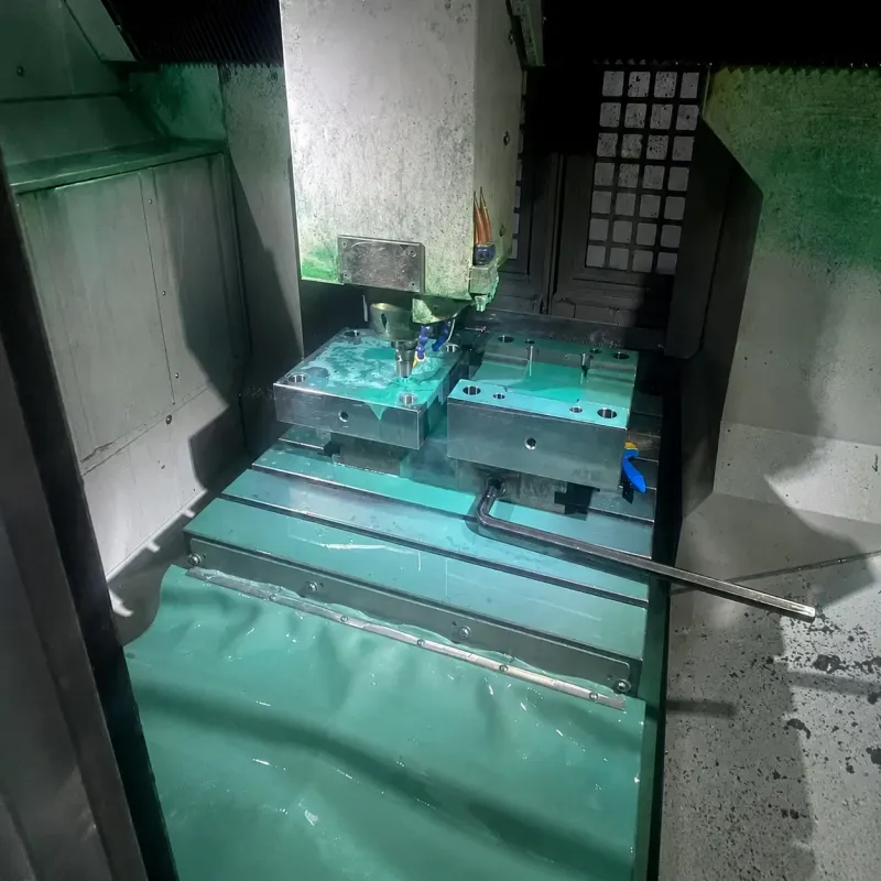
An exit bead sits inside the trim line, on the binder area that supports the blank next to the cavity. It controls the last 20 to 50 mm of flange that feeds the cavity wall and holds that wall at a stable thickness. Exit beads are common on door inners and floor parts, where the trim line sits far from the die radius and the flange would otherwise feed freely at the end of the stroke.
A lock bead sits where the blank must not move. It goes on the draw ring or on a trim edge, is 30 to 50 percent deeper than a working bead, and is often placed in pairs. A lock bead along a 500 mm edge at 1.5 kN per mm adds 750 kN of drag, so it is a tonnage decision as much as a forming decision. Check the total against the press rating early, because a lock bead added at tryout can push a die past its machine.
Two placement rules save tryouts. Keep a bead continuous around a corner, or break it through a designed taper, because an abrupt bead end concentrates strain and pulls a split at that exact point. Space adjacent beads at least 15 to 20 mm apart so the steel between them bends independently and the binder face does not dish between the ribs under cushion load.
Binder Force, Cushion Pressure and Contact Area
The binder is sized by pressure, not by force. Cushion tonnage on a double action press runs at 20 to 40 percent of press capacity, and the number that reaches the sheet is that force divided by the contact area of the blank. A 1,500 kN cushion acting on a 300,000 sq mm blank face delivers about 5 MPa. The same cushion acting on a 1,000,000 sq mm blank face delivers 1.5 MPa. Blank size and window cuts change the pressure, so the setup sheet belongs in MPa.
Working pressure lands between 1.5 and 4 MPa on steel. It rises with blank thickness, because a 2 mm blank needs more pressure than a 0.8 mm blank to hold the flange flat. It rises with coating, because galvanized sheet has a lower friction coefficient and slides more freely under the same load. It also rises with draw depth, because a deeper part needs a tighter grip over a longer flange travel.
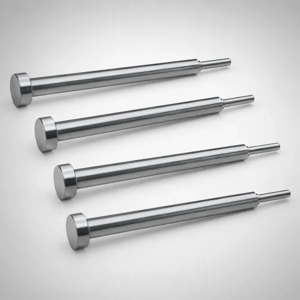
Low binder pressure shows up as wrinkles that begin at the flange edge and grow inward as the draw deepens. High binder pressure shows up first as a bright polished band on the flange, then as tearing at the punch radius. On a progressive die the binder is the pressure pad, and pad force is set the same way, with a 10 to 20 percent margin above the force needed to hold the strip flat.
Gas springs and cushions do not hold constant force through the stroke. A nitrogen cylinder bank set at 400 kN at the top of the stroke reaches 500 to 550 kN at 60 mm of travel, because gas force rises as the volume compresses. That 20 to 35 percent rise over-restrains the flange in the last third of the draw. Size a gas bank on the force at the bottom of the stroke, and read the force curve rather than the single number on the cylinder label.
Binder and Draw Ring Hardware
The binder face is a wearing surface. It carries the full cushion load over a fraction of a square metre, and every blank slides 20 to 60 mm against it. Two consequences follow: the face needs hardness, and the beads need to be replaceable.
Binder plates in 1.2311 or 1.2738 pre-hardened at HRC 30 to 34 suit low volume work and short runs. Tooling above 100,000 hits belongs in hardened inserts at HRC 56 to 60, with wear plates or hardened strips keyed into the binder around the bead. Bead inserts should be separate blocks, so a worn bead can be ground, shimmed or replaced without recutting the binder face or re-machining the die entry.
The addendum radius, where the binder meets the die entry, runs R8 to R15 and sets how sharply the flange turns into the cavity. A radius at the low end, R8, gives a tighter turn and a shorter addendum, but it also raises contact pressure at the entry and drives scoring. An R12 to R15 entry radius spreads the load and is the safer choice on coated or high strength sheet.
Lubrication belongs in the hardware decision. A dry or lightly oiled flange scores the entry radius and raises friction by 20 to 40 percent, which changes the draw force the cushion has to balance. Grooved binder faces that carry oil, and bead surfaces polished along the direction of material flow, hold friction stable across a full shift instead of drifting from the first panel to the last.
Corner radius on the draw ring deserves the same attention. Corners carry 1.5 to 2.5 times the strain of a straight side on a box shaped panel, so a corner entry radius is opened 2 to 4 mm larger than the straight sections, and the bead is run lighter there or stopped short of the corner.
Tuning Beads with Shims, Grinding and Polish
Tryout tuning moves in 0.05 to 0.10 mm steps, never in millimetres. Because restraining force changes 3 to 10 times faster than penetration, a 0.10 mm shim is already a coarse adjustment on a 1 mm sheet. The draw depth rules that set how much material a stage has to feed are covered in the deep draw die guide, and the same shim discipline applies at every stage.
The order of adjustment matters more than the size of the step. Set binder pressure first, because it moves the whole flange uniformly. Tune penetration next at the bead that controls the failure. Then change bead length by grinding a break or bolting in a segment. Change lubrication last, because it is reversible and it alters friction on every surface at once.

Shimming a bead insert raises it in the binder, and grinding the insert lowers it. Both changes are recorded on the setup sheet in 0.05 mm increments. A second tryout that repeats a setting without a record will chase the same defect twice. Shim stock supplied in 0.05, 0.10 and 0.20 mm laminated packs lets a die maker index penetration in one pass, followed by a panel and a thickness reading at the critical radius.
Polish direction is not cosmetic. Bead surfaces and entry radii are polished along the direction of material flow, never across it. A surface left with cross-polish marks at 0.4 to 0.8 micrometre Ra in 90 degree grooves raises friction and traps the coating peeled from galvanized sheet. Oil pockets of 0.05 to 0.10 mm depth, produced by a fine stone drawn in the flow direction, hold lubricant and keep drag repeatable across a shift.
Read the panel, not the dial. A flange showing a bright polished band has been ironed against the bead and is over-restrained. A flange with a dull, undisturbed surface never touched the bead hard enough to be restrained. Both readings cost nothing and both arrive with the first panel off the press.
Forming Simulation and Penetration Verification
A forming simulation is the only place a bead can be changed for free. Most solvers model a draw bead as a line force rather than as solid geometry, and the accuracy of that line force depends on the penetration value and the bead model used. A 2D section bead model and a line bead model return different restraining curves for the same rib, so the model type belongs in the report next to the result.
The acceptance numbers are straightforward. Balance fill so the last point to fill lands within 5 percent of the simulation target, hold thinning under 20 percent on mild steel and under 15 percent on steel at 590 MPa and above, and keep edge strain inside the forming limit diagram with a 10 percent margin. Check punch radius strain separately, because that is where a bead dragging too hard shows first. The design rules that make high strength sheet usable at those strain limits are set out in the high strength steel stamping guide.
Simulation also sets the blank. Adding a bead changes blank size by 10 to 30 mm on a typical flange, and it shifts the trim line with it. Run the model with the real blank outline and the real bead arrangement rather than an idealised rectangular blank, because the corners are where a bead either holds or releases the flange.
Certify the real bead before hard cutting. Cut one bead insert soft, measure penetration with a height gauge along its full length, and press a panel. If the thickness reading at the critical radius matches the simulation within 5 percent, harden the insert. If it does not, adjust penetration rather than pressure, because pressure moves the whole flange while penetration moves one failure.
Defects Traced to the Bead
Most press shop defects map to a bead or binder setting, and the mapping is direct enough to diagnose from the panel in hand.
Binder scoring and galling appear when the entry radius is too tight or binder pressure is too high. The surface shows metal transfer and the flange shows score lines. The cause is contact pressure above roughly 6 MPa on a radius under R8 with marginal lubrication. Open the radius, lower the pressure and repolish in the flow direction.
Tearing at the punch radius appears when the bead is too deep. The flange feeds too little material, the wall at the radius stretches past its limit, and the panel splits. Reduce penetration in 0.1 to 0.2 mm steps and re-read thickness at the radius after each pass. A tear that moves from the radius out to the flange edge means the bead was correct and the blank was short.
Wrinkles and oil-canning appear when the bead is too shallow. The flange feeds faster than the cavity can accept, the surplus gathers at the entry, and the trimmed panel carries a loose, wavy surface. Increase penetration or add bead length. Oil-canning that survives trimming points to a step bead that is stiffening the flange without restraining it.
Bead witness marks on the visible face come from too small a bead radius, from a bead running over a Class A surface, or from insufficient clearance at the bead. An R3 bead against a 1.2 mm sheet leaves a line 0.05 to 0.10 mm deep that no amount of polishing in the cavity removes. Move the bead into the trim scrap, or open the radius to R6.
Springback is the defect that arrives after the panel leaves the die. A flange restrained by a bead and then released carries residual stress that curls it back 0.5 to 3 mm on a 500 mm flange. Where the bead cannot be changed without losing restraint, the correction belongs in the tool surface, and the methods are set out in the springback compensation guide.
Bead Wear, Inspection and Replacement Intervals
Draw bead inserts are consumables. They slide under load on every stroke, they take the abrasive action of coated and high strength sheet, and they change shape slowly enough that no one notices until dimensions drift. A worn bead loses 10 to 25 percent of its restraining force, which is equivalent to reducing penetration by 0.2 to 0.5 mm.
Inspect beads every 20,000 to 50,000 hits. Measure bead height and radius with a height gauge and a radius gauge, then check the surface for galling, coating pickup and a flattened radius. Record the numbers, because a 0.2 mm change in bead height over 100,000 hits is normal while the same change over 20,000 hits points to a lubrication or a material problem.
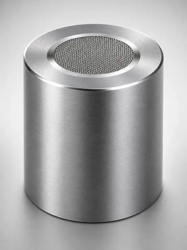
Wear rates vary by sheet. Mild steel runs at 0.001 to 0.003 mm of bead height per 100,000 hits, galvanized steel at 0.003 to 0.006 mm, and steel at 590 MPa and above at 0.005 to 0.012 mm with a micro-cracked surface that raises drag and scoring at the same time. Carbide inserts and PVD coatings of 2 to 5 micrometres extend the interval by 2 to 4 times on coated and high strength sheet.
A weak bead also changes the tonnage balance. When restraining force falls 20 percent, the cushion has to carry more of the flange and the draw force rises, so the press margin needs rechecking against the original calculation, which is set out in the press tonnage guide for stamping dies.
Plan replacement rather than repair. A bead insert ground 0.3 mm undersize cannot be shimmed back into specification without changing its radius, and the repaired bead then behaves differently from its neighbours on the same panel. Keep a spare set of bead inserts in the die spare parts inventory against the shot count that will require them.
Draw Bead and Binder Design FAQ
Q1. What is the difference between a draw bead and a binder?
The binder is the pressure ring that pinches the blank against the die face under cushion load, typically 1.5 to 4 MPa. A draw bead is a rib on that ring that forces the sheet to bend and drag, adding 0.2 to 0.6 kN per mm of length on a full bead. The binder holds the flange; the bead restrains its movement.
Q2. How deep should a draw bead be?
Bead height runs 3 to 8 mm and penetration 2 to 4 mm, with a gap of sheet thickness plus 0.03 to 0.10 mm. Move penetration in 0.05 to 0.10 mm steps during tryout, because restraining force changes 3 to 10 times faster than penetration and a 0.5 mm move can double the drag.
Q3. Which bead type gives the most restraining force?
A lock bead at 1.0 to 2.0 kN per mm, compared with 0.2 to 0.6 kN per mm for a single full bead and 0.05 to 0.15 kN per mm for a step bead. A lock bead is 30 to 50 percent deeper than a working bead and belongs where the blank must not move, such as a draw ring or a trim edge.
Q4. Why does my panel wrinkle even with the cushion at maximum?
Pressure is force divided by contact area. A cushion delivering 1,500 kN over a 1,000,000 sq mm blank face applies only 1.5 MPa, which is below the working band. Check the pressure at the flange, not the cushion rating, and confirm that bead penetration is actually restraining the flange rather than acting as a stiffening rib.
Q5. How often do draw beads need attention?
Inspect bead height, radius and surface every 20,000 to 50,000 hits, and expect a 10 to 25 percent loss of restraining force before replacement. On high strength and coated sheet, carbide inserts or PVD coatings of 2 to 5 micrometres stretch that interval by 2 to 4 times. Tools built for that maintenance regime are covered on the stamping die manufacturing page.
The Bottom Line
Draw bead and binder design reduces to a short list of numbers. Bead height 3 to 8 mm, bead radius 3 to 6 mm, gap of sheet thickness plus 0.03 to 0.10 mm, penetration 2 to 4 mm, addendum radius R8 to R15. Binder pressure 1.5 to 4 MPa from a cushion at 20 to 40 percent of press capacity. Bead drag of 0.2 to 0.6 kN per mm on a full bead and 1.0 to 2.0 kN per mm on a lock bead. Tune in 0.05 to 0.10 mm steps, inspect every 20,000 to 50,000 hits, and hold penetration within 0.1 mm in simulation before any insert is hardened.
Those figures decide whether the flange feeds at a rate the cavity can accept, and they explain why the same panel can tear on one die and wrinkle on another with identical cavity geometry. DieStrike builds draw dies and stamping tooling to IATF 16949 across 120+ machines, holding mold tolerance to ±0.005 mm with ±0.002 mm on wire EDM and jig grinding, HRC 62 max on hardened edges, standard components in 3 to 7 days and full tool lead times of 2 to 5 weeks. Tier-1 programs for TE, Amphenol, Luxshare and Dongshan run on the same process. Send the blank outline and the intended bead layout and we will return a forming review before the inserts are cut.
KEEP READING
Related Reading
How to Design for High-Strength Steel Stamping
Springback, edge cracking and the bead drag that has to double when the sheet reaches 780 MPa and above.
Read articleArticleHow to Calculate Press Tonnage for Stamping Dies
Shear force, cushion load and the margin that keeps a draw die off the press frame stops.
Read articleIndustryAutomotive Stamping Dies and Tooling
Draw dies, progressive dies and trim tooling for body panels, seats, underbody and battery structures.
Read articleServiceStamping Die Manufacturing
IATF 16949 die building with bead and binder planning, HRC 62 max edges and 2 to 5 week lead times.
Read articleNEXT STEP
Ready to Start Your Mold?
Send us your element dimensions or part numbers — our team responds within 24 hours with pricing and lead time.

Written by
Ray ChanMold Buyer's Guide Author · Precision Mold Manufacturing Specialist. Ray helps global importers, distributors and OEMs source factory-direct molds and mold parts.