
Air Bending vs Coining vs Bottom Dead Center: Which Die Wins
Table of Contents
A 1.5 mm DP980 bracket released for air bending came off the first production lot with a 9 degree angle spread. The weld fixture, built assuming 90 degrees, needed three shim iterations before the assembly closed. The same print tooled as a coining die would hold the angle inside 0.5 degrees. But that die costs several times more per matched cavity pair, and its inserts crack once the blank hardens past what tool steel can take. Bending mode sets die geometry, press selection and cost ceiling before anyone cuts steel.
The scope is the three contact modes a sheet sees between a punch and a die, and how each behaves across tonnage, springback, accuracy, tool life and money.
The Snapshot
- A tonnage ladder with 25 rungs of difference. A 2 mm DC01 bend on a 16 mm V-die needs 30 to 60 kN per metre of bend length in air bending. Bottom forming multiplies that by 3 to 5, and coining multiplies it again by 3 to 5.
- Springback is almost entirely an air-bend bill. Air bending returns 1 to 4 degrees on mild steel and 5 to 15 degrees on advanced high-strength steel. Coining holds the corner near zero because the die calibrates it under pressure.
- Accuracy bands: 1.0 mm to 0.05 mm. Air bending holds plus or minus 0.5 to 1.0 mm on leg length. Bottom forming reaches plus or minus 0.25 mm. Coining lands at plus or minus 0.05 to 0.1 mm, but only inside a 0.03 mm material thickness window.
- Tool cost and tool life move in opposite directions. Air bend tooling runs 3 to 5 times cheaper per setup and one V-die covers a 3:1 thickness range. Coining needs matched punch and die cavities per part and drops die life to 50,000 to 150,000 hits unless the surfaces are hardened or coated.
Why the Bend Mode Decision Comes Before the Die Design
Two parts with identical drawings can require completely different tooling. The difference is not the geometry. It is how much the corner must be held, how hard the press can hit, and how consistent the incoming coil is. The bend mode answer sets all three. On automotive programs the decision lands with the die budget in DFM, across the connector clips and chassis brackets in the automotive work we build.
What Air Bending Actually Does
In air bending the punch pushes the sheet into the die opening without ever reaching the bottom. Only three contact points exist: the punch nose and the two die shoulders on the flanks of the V. The sheet between the shoulders stays suspended, which is why air bending is less accurate than the contact modes.
The mechanics matter because they explain the numbers. The inner fiber compresses under the punch radius while the outer fiber stretches, and only a band of material near the punch tip yields plastically. When the punch retracts, the elastic rotation returns to the part as springback.

Tonnage is the cheapest part of the story. A 2 mm DC01 low-carbon steel bend on a 16 mm V-opening draws roughly 30 to 60 kN per metre of bend length. Air bending runs on presses sized for the blank, not for the corner.
The inside radius in air bending is not set by the punch. It is set mostly by the V-opening: the classical rule of thumb puts the achieved radius near 0.156 times the die opening, so a 16 mm V produces roughly a 2.5 mm radius. That is why one V-die covers a 3:1 thickness range.
Stroke depth controls angle, so the brake or press needs a repeatably positioned stroke. Angle accuracy in production lands at plus or minus 1 to 2 degrees with leg lengths held to plus or minus 0.5 to 1.0 mm. Every degree beyond that is bought with compensation, not with a harder hit.
What Bottom Forming Changes
Bottom forming, called bottom dead center forming on a brake, takes the same V-die architecture and drives the punch until the sheet briefly touches the die floor. The contact that was three points in air bending becomes a short flattening action along the bottom pad of the die. The flanks stay mostly free, but the zone under the punch receives a calibration squeeze.
The tonnage step is the price. Bottom forming needs 3 to 5 times the air-bend force on the same bend: a corner that bent at 45 kN per metre now wants 140 to 220 kN per metre on a 2 mm sheet. That multiplier pushes many shops from a brake onto a stamping press, and it forces a tonnage check on the existing machine before the die order is signed.

What the extra force buys is partial correction. The touch against the floor re-yields the region under the punch and reduces the springback the part keeps, typically trimming the residual angle error to around 1 degree or less on mild steel. Leg length accuracy improves to about plus or minus 0.25 mm because the punch stroke now bottoms against a fixed die surface instead of stopping in mid-span air.
Choose bottom forming when air bend springback is too large for compensation to absorb but the drawing does not demand the 0.05 to 0.1 mm corner control that justifies coining tooling. The die floor takes repeated hammering, so the pad that touches the sheet is the wear point and belongs in a replaceable insert.
What Coining Demands
Coining closes the loop between the punch and a matched die cavity and presses hard enough that the surface of the corner plastically flows into the steel. The real description is a local thickness reduction of 20 to 40 percent in the bend zone, achieved at 3 to 5 times bottom-forming tonnage, which itself was 3 to 5 times air-bend tonnage.
That force produces the payoff: a calibrated corner. Because the punch nose and die cavity carry matching geometry and the material is squeezed until it conforms to both, the finished angle copies the tool radius. Springback in coining is near zero, typically under 0.5 degrees, and leg lengths land at plus or minus 0.05 to 0.1 mm.

The demand comes with the accuracy. Coining works inside a 0.03 mm material thickness window because the punch-to-die cavity is a closed volume. Feed the die a sheet 0.05 mm thick and the excess metal has nowhere to go: tonnage spikes, the corner splits or the die cracks. Feed it a sheet 0.05 mm thin and the corner loses calibration. This is why coining demands plus or minus 0.03 mm gauge control and why die setters shim stacks at setup.
The second demand is the tool itself. A coining die is a matched pair: one punch and one cavity per part geometry, with no generic V-opening that covers a thickness range. Every radius or leg-length change re-opens the cavity machining. On a progressive die this multiplies across stations, so a coining station is a separate line in the die budget.
Springback Across the Three Modes
Springback is the elastic rotation the part returns after the load comes off, and it is the single largest accuracy threat in bending. Air bending carries the whole penalty: the part yields only in a band under the punch, the rest of the bend stays elastic, and the recovered angle moves 1 to 4 degrees on mild steels such as DC01 and 5 to 15 degrees on advanced high-strength grades above 600 MPa.
Bottom forming spends part of its tonnage multiplier re-yielding the punch-pad zone against the die floor, so residual springback falls to roughly 0.5 to 1 degree on mild steel. It does not eliminate springback on AHSS because the flanks still bend in air around the shoulders, and a 3 to 6 degree return on a 980 MPa grade is normal even after bottoming.
Coining suppresses springback to under 0.5 degrees by construction. The corner is work-hardened into a calibrated cavity, and the material in the bend zone has been reduced in thickness. The residual angle depends on the tool geometry, not on the coil lot, which is why coining is specified when the drawing tolerance is tighter than one degree.
For air bending there are three compensation routes before anyone reaches for coining. Over-bend: aim the stroke one to three degrees past target so the recovered angle lands on print. Bevel the punch: grind an angle into the punch nose so the spread across a lot averages out. Angle-correction sensing on modern brakes closes the loop within one degree per stroke. The arithmetic behind each route belongs to our springback compensation guide.
Accuracy Bands and Gauge Control
Stack the three modes against the same drawing and the bands separate cleanly. Air bending: leg length plus or minus 0.5 to 1.0 mm, angle plus or minus 1 to 2 degrees. Bottom forming: leg length around plus or minus 0.25 mm with the angle held near one degree. Coining: leg length plus or minus 0.05 to 0.1 mm and angle under half a degree. Each step narrows the band by a factor of four to ten and raises tonnage and tool cost by an order of magnitude.
The accuracy number is only reachable if the incoming coil matches the assumption. In air bending a 0.05 mm thickness swing changes the radius and angle a little, and the process absorbs it. In coining the same swing changes the closed cavity volume directly: the die has no room to forgive. A coining program needs a gauge record per coil, typically plus or minus 0.03 mm to nominal, and incoming inspection that measures it rather than trusting the certificate.
Tolerance stack discipline applies to the tool too. The punch-to-die cavity clearance in coining is a few hundredths of a millimetre, so the die itself has to be built inside the shop's precision band. We hold mold and die working geometry to plus or minus 0.005 mm, with plus or minus 0.002 mm on EDM and jig-grinding for matched surfaces. A cavity cut loose at build time cannot be shimmed into calibration later.
Bottom forming sits in an uncomfortable middle on gauge sensitivity. It tolerates coil variation better than coining but punishes inconsistent stroke more than air bending. The press repeatability number, typically under 0.02 mm on a good hydraulic with programmable stroke, decides whether the claimed 0.25 mm is real. Verify the press, not just the print.
Bend Ratio and Inside Radius Rules
Air bending lives or dies on the V-opening ratio. The working rule is that the die opening equals 6 to 12 times the sheet thickness. At the generous end, 12 times, the bend needs more tonnage per degree but stretches the outer fiber less. Below 6 times the opening the sheet is forced around too tight a shoulder and the outer fiber tears.
| Parameter | Air bending | Bottom forming | Coining |
|---|---|---|---|
| Tonnage vs air bend | 1x baseline | 3 to 5x | 9 to 25x |
| Springback, mild steel | 1 to 4 degrees | about 1 degree | under 0.5 degrees |
| Leg length accuracy | plus or minus 0.5 to 1.0 mm | plus or minus 0.25 mm | plus or minus 0.05 to 0.1 mm |
| Gauge sensitivity | Low, radius follows V-opening | Moderate, stroke must repeat | High, 0.03 mm window |
| Tooling per geometry | One V-die covers 3:1 thickness range | Dedicated pad and stroke control | Matched punch-die cavity pair |
| Die life | High, line contact only | Floor pad wears first | 50,000 to 150,000 hits uncoated |
← swipe to scroll →
Table note: bands are typical published industry values for 1 to 3 mm carbon and HSLA sheet. Confirm against the coil certificate, the press tonnage curve and a bend test on the actual grade before releasing the die design.
The inside radius floor follows the same logic. Mild steel tolerates an inside radius of 1 to 1.25 times the thickness. A 600 MPa HSLA grade needs 2 to 4 times the thickness before the outer fiber survives the stretch, and martensitic grades above 1,200 MPa push the practical minimum further still. These ratio rules bind the die design in all three modes, and they bind hardest in coining because the cavity radius is frozen into matched steel. Material formability is checked before mode selection, not after.
Tonnage and Press Requirements
The tonnage ladder has real consequences for the machine. An air bend on 2 mm DC01 at 30 to 60 kN per metre runs on almost any brake or press that fits the blank. Bottom forming on the same corner asks for 3 to 5 times that. Coining asks for 9 to 25 times, where a 200 mm bend length that needed 12 tonnes in air can want over 100 tonnes in the die.
The press type matters as much as the number. Hydraulic presses with programmable stroke and holding dwell are the natural home for bottom forming and coining, because calibration happens at bottom dead center and the hydraulic can hold pressure there. A mechanical crank press stores energy in the flywheel and releases it along a fixed crank curve. The coining spike hits where a crank has the least torque, so mechanical presses stall or overload.
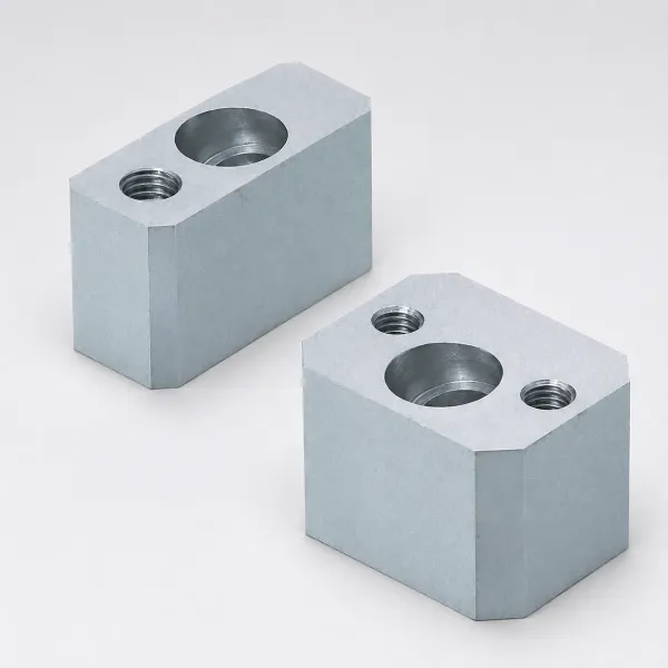
The tonnage math and safety margin for bending stations sit in our press tonnage calculation guide. The one-line rule: size the press on the mode, not on the drawing. A coining station tooled onto a crank press survives setup shots and then cracks inserts once the gauge drifts and the spike climbs. Rerun the tonnage check before the first hit, not after the first crash.
Tooling Wear, Life and Steel Choice
Contact geometry sets the wear rate. In air bending the sheet rides the die shoulders and the punch nose as line contact around a radius, and the fibre stress at that line runs in the 300 to 1,000 Mpsi range. The wear is concentrated and slow: a hardened bend punch runs high hundreds of thousands of hits before the radius polishes out enough to move the angle band.
Coining changes the physics. The load sits on surface area instead of a line, and every hit work-hardens the corner while hammering the cavity walls. Unguarded, the die steel cold-welds to smeared blank material and the cavity picks up galling within thousands of hits. Practical coining tooling goes to carbide or hardened tool steel at HRC 60 and above, and uncoated life still falls to 50,000 to 150,000 hits before regrind. A DLC or nitride coating is the standard multiplier.

Our heat-treat ceiling is HRC 62 max, and a coining cavity is where that ceiling earns its keep: at 20 to 40 percent thickness reduction the surface pressure is high enough that pre-hardened plates at HRC 30 to 40 smear within a shift. Regrind intervals should be written into the die file per mode. An air bend punch can go 200,000 to 500,000 hits between dress-ups; a coining cavity wants inspection every 20,000 to 50,000 hits and a regrind or re-coat at 50,000 to 150,000.
Cost and Setup Comparison
Air bend tooling is 3 to 5 times cheaper per setup than the alternatives, and the real economy is better than that because of flexibility. One V-die and one punch nose radius cover bends across a 3:1 thickness range, so a brake tooling library amortises across the whole shop.
Bottom forming tooling still uses V-die architecture but wants a defined floor pad and repeatable stroke, so cost rises through die-block machining and press fixturing. Setup time is the hidden cost: bottoming to a few hundredths of a millimetre takes trial hits, and trial hits on a large die are hours.
Coining pays for matched cavities per geometry and per grade. Tool cost per station climbs, gauge-control cost per coil climbs, and change control becomes a die-modification event instead of a program edit. The offsetting numbers: near-zero scrap on angle-critical features and cycles that skip the settle-and-measure loop.
Run the crossover on volume and tolerance together. Below a few tens of thousands of parts with a one-degree band, air bending with over-bend compensation wins. Above several hundred thousand hits with a half-degree band and stable gauge, coining's amortised die cost per part collapses while the rework avoided pays the tool surcharge. Bottom forming is worth defending when the volume is mid-range and the band is 0.25 mm.
The Decision Matrix
Read the matrix on four axes: the angle and length tolerance the drawing carries, the gauge record the coil supplier can prove, the annual hit count, and the hardness or strength class of the blank. Air bending wins whenever all four are forgiving: plus or minus 1 to 2 degrees, ordinary commercial coil at plus or minus 0.05 mm, volumes under a few tens of thousands, and mild steel below 340 MPa. Coining wins when the band is under half a degree, the mill ships plus or minus 0.03 mm gauge, volumes run into the hundreds of thousands, and the grade is soft enough to flow into the cavity.
Bottom forming holds the middle: a plus or minus 0.25 mm leg target, mid-range volume, a press that repeats its stroke within 0.02 mm, and a grade that springs back more than compensation absorbs but not so hard that coining tooling would survive only 50,000 hits. When two axes point one way and two the other, the tie-breaker is change control: products with living drawings should stay in air bending, where every revision is a program edit.
| Program condition | Air bending | Bottom forming | Coining |
|---|---|---|---|
| Angle tolerance needed | plus or minus 1 to 2 degrees | about 1 degree | under 0.5 degrees |
| Leg length tolerance | plus or minus 0.5 to 1.0 mm | plus or minus 0.25 mm | plus or minus 0.05 to 0.1 mm |
| Coil gauge control required | Commercial, plus or minus 0.05 mm | Plus or minus 0.04 mm | Plus or minus 0.03 mm with records |
| Annual hits | Any, flexible tooling library | Tens of thousands | 100,000 to millions, coated |
| Blank strength class | Mild through 980 MPa with radius rules | Mild through 600 MPa | Below 1,000 MPa, refuse above |
| Drawing changes weekly | Yes, edits the program | Costly, re-shims the pad | No, remachines the cavity |
← swipe to scroll →
Table note: bands are typical values for 1 to 3 mm sheet on hydraulic and mechanical presses. Validate with bend tests on production coils before the die design freeze, and put the results in the DFM report.
The tooling itself is where our shop touches this decision. Bend and coining inserts, matched punch tips and the hardened wear pads are built in the same stamping die program as the progressive layout, on IATF 16949 process records, with tool lead times of 2 to 5 weeks and standard components shipping in 3 to 7 days.
When to Refuse Coining on AHSS
There is a line where coining stops being a precision option and becomes a die-breaking liability: above roughly 1,000 MPa tensile strength. Coining forces the blank to flow into the cavity at 20 to 40 percent thickness reduction, and a martensitic or complex-phase grade above 1,000 MPa pushes back with a flow stress that tool steel cannot durably exceed. The die steel cannot beat the blank.
The failure sequence is predictable. The first thousand hits look excellent and the angle is dead on. Then the cavity surface micro-welds to smeared blank material, galling pulls metal out of the insert on every upstroke, and the calibrated corner drifts while cracks seed at the cavity radius. Tungsten carbide inserts buy hardness but trade toughness: under coining spike loads on 1,200 MPa material, chipping at the cavity edge replaces galling.
Refuse the coining call and route the part instead. Air bend the corner at 2 to 4 times thickness inside radius on 600 MPa grades and more on martensitic, and pay the springback bill with over-bend, bevels or inline angle sensing. Where the drawing demands a calibrated feature in AHSS, split the feature: a sized pilot hole or a flat datum can be coined in a low-strain mode while the corner stays an air bend. The formability limits behind that split belong to the high-strength steel design guide, and the blank quality feeding either mode follows the clearance discipline of any well-built blanking die.
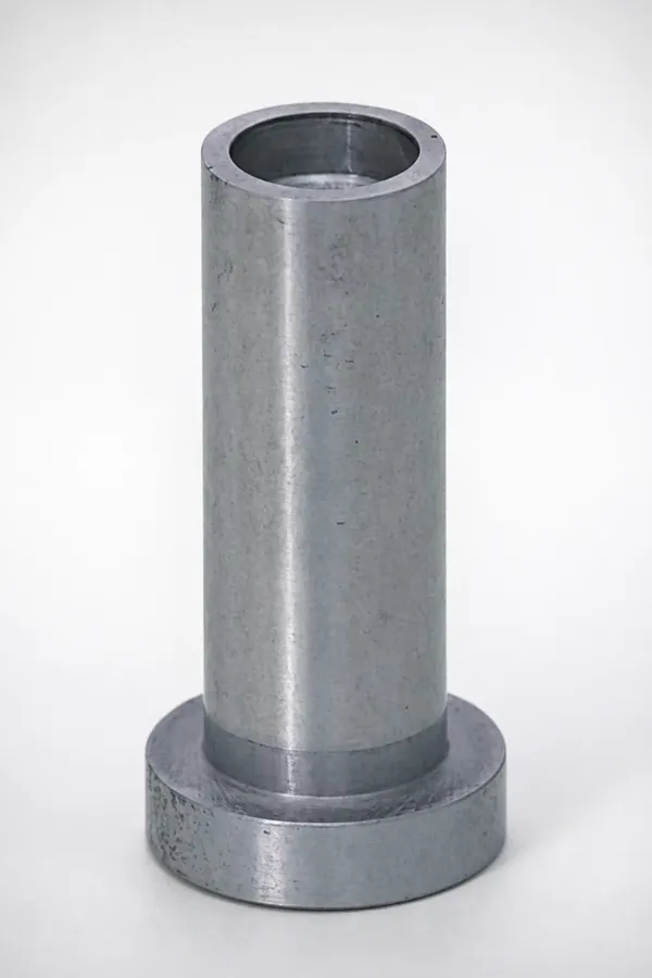
One more refusal rule deserves writing into the quotation: if the program cannot commit to a gauge record inside plus or minus 0.03 mm, no coining die should ship, whatever the drawing says. A coining tool handed to a buyer who buys the cheapest coil is a tool that will fail in production and be blamed on the die shop.
The Bottom Line
The three bend modes are one continuum separated by how far the punch travels and how much force follows. Air bending buys flexibility at 30 to 60 kN per metre on a 2 mm sheet and accepts plus or minus 1 to 2 degrees of springback. Bottom forming buys a calibrated touch at 3 to 5 times the force and about plus or minus 0.25 mm. Coining buys near-zero springback and plus or minus 0.05 to 0.1 mm at 9 to 25 times tonnage, paid back in matched cavities per geometry, a 0.03 mm gauge window, die life of 50,000 to 150,000 uncoated hits, and a hard refusal above 1,000 MPa.
Decide on tolerance, gauge evidence, volume and hardness in that order. Verify the press can hold stroke and shed the spike at bottom dead center, then let the drawing tolerance, not habit, pick the mode. A bend mode chosen correctly at DFM keeps the die file, the incoming inspection and the scrap rate telling one story for the life of the program.
KEEP READING
Related Reading
Fine Blank vs Conventional Stamping
Where burn-free edges and dimensional class justify a different process family entirely.
Read articleArticleHow to Calculate Press Tonnage for Stamping Dies
Cutting, bending and drawing force formulas and the safety margin before you buy the press.
Read articleArticleHow to Design for High-Strength Steel Stamping
Inside radius limits, springback budgets and tooling rules for 600 to 1,500 MPa grades.
Read articleServiceStamping Die Manufacturing
IATF 16949 progressive and station dies with tool lead times of 2 to 5 weeks.
Read articleNEXT STEP
Ready to Start Your Mold?
Send us your element dimensions or part numbers — our team responds within 24 hours with pricing and lead time.

Written by
Ray ChanMold Buyer's Guide Author · Precision Mold Manufacturing Specialist. Ray helps global importers, distributors and OEMs source factory-direct molds and mold parts.