
How to Select Ejector Sleeves: A Practical Guide for Thin-Wall Molds
Table of Contents
A thin-wall cup that sticks on the core costs you a shot. A thin-wall cup that drags the core steel with it costs you a mold. Solid ejector pins push on points; ejector sleeves push on a full ring of material, and that one mechanical difference decides whether thin-wall parts release cleanly at 1,000,000 cycles or start showing drag marks at cycle 50,000.
Ejector sleeve selection looks simple from a catalog: pick an OD, pick a bore, pick a length. The reality is that the sleeve is a three-part tolerance stack — outer diameter, inner bore, and concentricity between them — and every one of those numbers changes how the part releases, how long the steel lasts, and how much flash the tool makes. This guide walks through the decisions in the order your mold designer actually makes them, and it ends with a checklist you can hand to any quoting engineer.
The Snapshot
- Annular ejection is what a sleeve does that a pin cannot: it pushes the part off around the full circumference of a core, applying 360° of force with no pierce mark and no point load.
- H7 bore / g6 OD is the working fit pair for standard ejector sleeves — bore +0.015/0 mm, OD -0.005/-0.020 mm — with sleeve-to-center-pin sliding clearance held around 0.005 to 0.015 mm.
- ≤ 0.015 mm concentricity is the runout budget between bore and OD on straight sleeves; stepped series hold ≤ 0.010 mm. Beyond that, the sleeve drags on one side and the part wears unevenly.
- HRC 58-62 is the working hardness band for sleeve steel in production tools — SKD61 nitrided to 900+ HV surface, SKH51 through-hardened for abrasive resins.
- 150 mm+ ejection strokes are practical with stepped sleeve-pin sets, which is how deep-boss and thin-wall packaging molds stay straight over their full stroke.

What Ejector Sleeves Do
An ejector sleeve is a hollow, hardened tube that slides over a center pin (often called a core pin) and pushes the molded part off the core. The center pin forms the internal geometry — a boss bore, a tube ID, a deep hole — and the sleeve does the ejection. The two parts work as a matched pair: the pin stays put while the sleeve strokes forward, or both move together with a delayed sequence for two-stage release.
That is why the terms multiply in the market: ejector sleeve, sleeve pin, and pin sleeves all describe the same family of components. A "sleeve pin" is the assembled unit of sleeve plus center pin, and "pin sleeves" is the colloquial plural. When you see ejector sleeve injection molding references in a catalog, the part being described is almost always a matched sleeve-and-pin set for annular ejection.
The force story is the reason sleeves exist. A solid pin transfers ejection force through its tip — a contact area of a few square millimeters. On a thin-wall part, that point load punches a witness mark, distorts the wall, or pierces right through. A sleeve transfers the same force through a ring of material, spreading the load across the entire rim of the feature being ejected. The result is lower local stress, no pierce mark, and a part that leaves the core square instead of tilted.
There is a second job sleeves do that pins cannot: they shield the core. In a thin-wall mold, the plastic shrinks onto the core steel during cooling. On a long core, that shrink grip is strong enough to pull the core with the part. The sleeve breaks the grip by shearing the material off the core face right at the parting line, so the core never sees the full stripping force. Run a thin-wall tool without sleeves and the core is the component that fails first — usually bent, sometimes snapped.
DieStrike builds ejector sleeves and center pins as matched, factory-aligned sets: the bore and OD are ground from the same setup and the concentricity is reported per pair on the CMM. If you are buying sleeves from a supplier who cannot tell you the measured runout of the set, you are buying a tolerance lottery ticket, and the mold pays the jackpot.
Thin-Wall vs Standard Applications
"Thin-wall" is not a marketing word; it is a measurable regime. Molds are called thin-wall when nominal wall thickness drops to 1.0 mm or below — often 0.4 to 0.8 mm — and the flow-length-to-wall ratio climbs past 150:1. At that geometry, the part cools in 2 to 6 seconds, cycles in 4 to 8 seconds, and shrinks onto the core with a grip that standard ejection cannot reliably break.
Thin-wall applications are where ejector sleeves earn their keep:
- Thin-wall packaging: cups, tubs, bottles, and closures with walls at 0.3 to 0.8 mm. The sleeve pushes the entire sidewall rim off the core in one 360° stroke. A solid pin through a 0.5 mm wall punches a visible mark on the inside of the cup and distorts the rim.
- Medical disposables: syringe barrels, tip caps, and micro-fluidic parts. Mirrored sleeve bores (Ra 0.1 µm or better) eject clean, gall-free, with no drag lines in the bore.
- Automotive connectors and housings: thin-wall housings with terminal cavities and latches. Stepped sleeve-pin sets hold concentricity over long strokes while nitrided SKD61 resists glass-filled PA66 and PC/ABS compounds.
- Deep-boss and tube features: any boss deeper than about 3 times its diameter, or any tube that must keep its internal diameter and surface finish. The center pin forms the ID; the sleeve releases it.
- Tall cores in standard molds: even a conventional mold with a 40 mm tall core and a 1.2 mm wall around it is a sleeve candidate. The rule is geometry, not industry.
Standard (non-thin-wall) molds use sleeves in three narrower situations: deep bosses that would buckle a solid pin, annular undercuts on the core side, and two-stage ejection sequences where the sleeve moves first and the pins follow. If the part is a simple flat plaque with ribs, solid pins are cheaper and faster to replace — the sleeve earns its cost only when the geometry demands annular force or core protection.
The telling sign that a tool should have used sleeves: drag marks on the inside of the tube, a bent center pin, or a witness ring where the solid pin pushed through the wall. All three appear in the first trial, and all three are avoided at the selection desk.
Sizing: OD, Bore, and Length
Sleeve sizing starts from the part geometry and works outward. The order matters: bore first, then OD, then length — and then a check that the wall between bore and OD survives the ejection load.
Bore (ID). The bore must clear the center pin with a light sliding fit, typically 0.005 to 0.015 mm on diameter. The bore number is therefore driven by the pin: bore = center pin OD + clearance. Standard bore diameters follow the same size ladder as core pins, so pair the sleeve with a pin you can actually buy. If the pin is custom, the sleeve bore is ground to match it — DieStrike grounds matched sets from the same setup so the pair cannot drift apart.
OD. The OD is the ejection surface. It should match the diameter of the feature being ejected — the boss OD, the tube OD, the wall ring — less any draft you want the sleeve face to follow. Two sizing rules dominate. First, keep the sleeve wall (OD minus bore, divided by two) at 0.8 mm or more where possible; below that, the sleeve starts to act like a thin ring and wears its bore edge first. Second, prefer catalog sizes: standard ODs at 0.5 mm increments, standard bores, and JIS B5009 / DIN 16756 head and bore dimensions so the sleeve drops into a DME or MISUMI pocket without rework.
Length. Sleeve length has three components: the land that stays in the cavity plate, the stroke the sleeve must travel, and the head that the ejector plate pushes on. The land should be 10 to 15 mm for a standard sleeve — long enough to keep the sleeve square, short enough to vent. The stroke is the distance the part must travel to clear the core: for thin-wall cups and tubes, that is typically the core height plus 1 to 2 mm of clearance. Add the head per the catalog standard and you have the total length.
Wall strength check. The sleeve wall carries the full ejection force in compression, and a thin-walled sleeve on a long stroke can buckle just like a thin pin. If the unsupported length-to-wall-thickness ratio passes roughly 20:1, step the OD: grind a larger OD on the return section and keep the small OD only where the part demands it. Stepped sleeves are the standard answer for deep-boss ejection, and stepped series hold better concentricity (≤ 0.010 mm) because the larger section stabilizes the grind.
Stroke depth. When the ejection stroke exceeds about 150 mm, move the sleeve-pin set to a stepped or two-stage design. A straight sleeve that long is grinding-challenged, drags on its own length, and deflects under load. Two-step center pins also provide delayed, dual-stage release for multi-cavity connector molds — the sleeve releases the part first, the pin follows, and neither component sees the full stripping force at once.
Materials: SKD61 vs SKH51
Two steels carry 90% of ejector sleeve work: SKD61 and SKH51, with M2 as the high-wear option. They are not interchangeable, and the choice is driven by the resin, not by habit.
| Grade | Hardness | Best for | Watch out for |
|---|---|---|---|
| SKD61 (hot-work) | 48-52 HRC, nitrided to 900+ HV surface | General thin-wall work, glass-filled PA/PC, hot molds, long strokes | Soft core under the nitrided case — resists wear, not abuse |
| SKH51 (high-speed) | 58-61 HRC through-hardened | Abrasive resins (30%+ glass), thin sleeve walls, high-cycle tools | Less tough than SKD61 — keep it away from shock-loaded thin edges |
| M2 (high-speed) | 61-64 HRC | Maximum wear resistance on long-glass and mineral-filled compounds | Grinding cost; best reserved for the bore/OD pair that actually wears |
← swipe to scroll →
SKD61 is the default sleeve steel. It is a 5% chromium hot-work steel that holds temper at running temperatures, nitrides cleanly to 900+ HV, and keeps enough toughness for long, thin sleeves. It is the right answer for most thin-wall packaging, general purpose work, and any mold that runs hot. When your resin is glass-filled or the tool runs past half a million cycles, the nitrided case is what saves you — plan for it in the spec, not as an afterthought.
SKH51 is the upgrade for abrasive service. As a high-speed steel it is through-hardened to 58-61 HRC, so there is no soft core under a thin case — a sleeve that wears through its nitriding still has hard steel underneath. It is the standard choice for sleeves carrying 30%+ glass fibers, thin sleeve walls, and high-cavitation tools where downtime is measured in lost machine hours. The trade is toughness: on shock-loaded thin edges, SKD61 survives where SKH51 chips.
M2 sits one step further up the wear ladder for long-glass and mineral-filled compounds, at 61-64 HRC. Reserve it for the pair that actually wears — usually the sleeve bore and the pin OD in the same position — and keep the rest of the set in SKD61 to control cost.
Coatings extend every grade. TiN and CrN at 2 to 4 µm cut galling on glass-filled resins, and nitriding is the baseline treatment for SKD61 sleeves. For a full breakdown of hot-work steel grades in ejection service, read our SKD61 vs H13 ejector pin guide — the same steel logic applies to sleeves, with SKH51 as the abrasive-resin answer.
The hardness band matters as much as the grade. Production sleeve steel runs HRC 58-62 in the working state (nitrided SKD61 surface, or through-hardened SKH51). Below that, the sleeve edge rolls over, the bore wears oval, and drag marks start showing on the part. Require the hardness range on the drawing and spot-check it at incoming inspection the way you would for any pin.
Tolerances and Concentricity
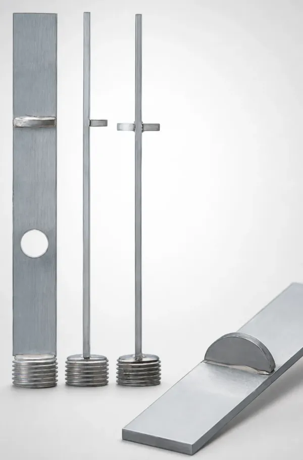
A sleeve has three tolerance zones that interact: the OD fit in the cavity plate, the bore fit over the center pin, and the concentricity tying the two together. Every failure mode in sleeve ejection traces back to one of these three.
OD fit. Standard sleeves grind the OD to g6, which lands at -0.005 to -0.020 mm below nominal. The cavity plate hole is bored to match, and the sliding clearance ends up around 0.01 to 0.03 mm. That clearance is the flash gate: too tight and the sleeve seizes when the mold reaches running temperature; too loose and low-viscosity resins feather out of the hole. If the sleeve OD clearance drifts past 0.03 mm, expect flash on LCP and PPS first.
Bore fit. The bore grinds to H7, +0.015/0 mm, and pairs with the center pin at 0.005 to 0.015 mm sliding clearance. The bore must stay round over the whole land: a worn or out-of-round bore grabs the pin, drags on the part ID, and leaves the classic bright stripe inside a tube or boss. Ground bores at Ra 0.1 µm are the working standard; when the part demands a mirror finish on its internal surface, DieStrike polishes the bore further to Ra 0.05 µm.
Concentricity. This is the number most buyers skip and the one that decides sleeve life. If the bore and OD are not coaxial, the sleeve wall thickness varies around the circumference: thick on one side, thin on the other. At ejection, the sleeve presses the part harder on the thick side, the thin side wears first, and the witness mark on the part is uneven. Straight series hold concentricity to ≤ 0.015 mm; stepped series hold ≤ 0.010 mm because the larger OD section stabilizes the grind. DieStrike reports measured concentricity per matched set on the CMM — ask your supplier for the same and you will filter out most of the market in one question.
The plate underneath. Sleeve accuracy is capped by the hole it runs in. Our die sets hold ejector plate hole positions to ±0.005 mm standard, with wire EDM at ±0.002 mm on critical features. If the sleeve is accurate but the plate hole is drifted 0.05 mm, the sleeve binds, the center pin wears, and the part tilts. Specify plate hole position tolerance on the mold drawing and measure it — the CMM catches what the eye never will.
Venting. A full-length close fit turns the sleeve into a piston: air has nowhere to go, ejection slows, and the sleeve drags. Keep the close-fit land at 10 to 15 mm and open up the hole behind it. Vent the boss or tube area where the part traps air against the core — thin-wall parts trap air harder than any other geometry.
When Sleeves Beat Solid Pins
The ejector sleeve versus solid pin decision is a geometry test, and it resolves cleanly in five cases.
- The ejection surface is annular. A tube, a boss, a cup rim — the material surrounds a core, so the ejector must surround it too. A solid pin under a tube pushes on a point and distorts the ring; a sleeve pushes the whole ring.
- The wall is thin. At 1.0 mm wall and below, a solid pin tip punches a mark through the wall or leaves a witness ring on the cosmetic side. The sleeve spreads the load over the rim and leaves the wall clean.
- The core is tall. Tall cores collect shrink grip, and the sleeve shears the part off the core at the parting line. This protects the core from the stripping force that bends unsleeved pins.
- The part must keep internal geometry. When the ID of a boss or tube is a critical dimension, the center pin forms it and the sleeve releases it — the ejection process never touches the formed surface.
- Two-stage release is needed. Sleeve-first, pin-after sequences release thin-wall parts in two steps and cut total stripping force per component. This is standard on multi-cavity connector molds.
Solid pins still win when the ejection surface is a flat face or a simple rib, when the pin is under 3 mm and the geometry is shallow, and when cost and replaceability outweigh cosmetics. A solid pin costs less, swaps in minutes, and needs no matched-pair concentricity. Do not sleeve a part that does not need it — but measure the wall and the core height before you decide, because "probably fine" is how thin-wall tools end up in the repair shop.
For the full comparison of forming versus release functions, see our core pin vs ejector pin guide — it covers the tolerance, steel, and failure-mode logic that also applies when you add a sleeve around a pin.
Selection Checklist
Run this gate list before the sleeve order goes out. Each item has a number so the review is quick.
- Wall thickness 1.0 mm or below: sleeve ejection required; verify the sleeve face covers the full wall ring.
- Bore = center pin OD + 0.005 to 0.015 mm sliding clearance; specify H7 (+0.015/0).
- OD fit in the cavity plate: g6 (-0.005/-0.020), sliding clearance 0.01 to 0.03 mm.
- Concentricity: ≤ 0.015 mm straight series, ≤ 0.010 mm stepped; require measured values per set.
- Sleeve wall thickness: 0.8 mm minimum; step the OD if the unsupported length-to-wall ratio passes 20:1.
- Land length 10 to 15 mm; open up the hole behind the land for venting.
- Resin abrasive (30%+ glass) or high cycle count: SKH51 or nitrided SKD61; coatings TiN/CrN for galling.
- Hot mold or long strokes: nitrided SKD61; stepped sleeve-pin set for strokes past 150 mm.
- Ejector plate hole positions within ±0.005 mm (wire EDM at ±0.002 mm on critical features).
- Standards: JIS B5009 / DIN 16756 head and bore dimensions, DME and MISUMI compatible for drop-in replacement; order matched sleeve-pin sets with CMM reports.
FAQ
What is the difference between an ejector sleeve and a sleeve pin? An ejector sleeve is the hollow tube; the sleeve pin (or center pin) is the solid pin it slides over. Together they form a matched set — the pin forms the internal geometry, the sleeve ejects the part around it. "Pin sleeves" is the same family of components under a different name.
When should I use an ejector sleeve instead of an ejector pin? When the ejection surface is annular (a tube, boss, or cup rim), when the wall is 1.0 mm or thinner, when the core is tall enough to collect shrink grip, or when the part must keep a critical internal diameter. Solid pins win on flat faces and shallow ribs.
How do I size an ejector sleeve? Start with the bore: center pin OD plus 0.005 to 0.015 mm clearance. Then the OD: the diameter of the feature being ejected, keeping the sleeve wall at 0.8 mm minimum. Then the length: 10 to 15 mm land plus the ejection stroke plus the head. Prefer catalog sizes in JIS B5009 / DIN 16756 with DME or MISUMI compatibility.
SKD61 or SKH51 for my ejector sleeves? SKD61 for general thin-wall work and hot molds — it nitrides to 900+ HV and keeps toughness. SKH51 (58-61 HRC, through-hardened) for abrasive resins with 30%+ glass and for thin sleeve walls where there is no soft core to wear through. M2 at 61-64 HRC for the hardest long-glass compounds.
What tolerances should ejector sleeves hold? Bore H7 (+0.015/0 mm), OD g6 (-0.005/-0.020 mm), concentricity ≤ 0.015 mm straight series and ≤ 0.010 mm stepped, with bore finish at Ra 0.1 µm (Ra 0.05 µm available). Hold ejector plate hole positions to ±0.005 mm so the sleeve accuracy is not wasted.
Why is my ejector sleeve dragging or leaving uneven marks? Check concentricity first — a runout above 0.015 mm presses the part harder on one side. Then check the OD clearance (0.01 to 0.03 mm), the land length (10 to 15 mm, vented behind), and the plate hole position. Uneven marks are almost always a tolerance stack problem, not a steel problem.
Make the Call
The difference between a thin-wall mold that runs 1,000,000 cycles and one that goes to the repair bench at 50,000 is written on the sleeve drawing: the fit pair, the concentricity, the land, the grade. Each of those numbers is a few lines on a spec sheet and a lifetime of avoided drag marks, flash, and bent cores.
Send us your part drawing and cavity plan and we will return a sleeve-and-pin layout with bores, ODs, lengths, fits, materials, and coating recommendations — with DFM feedback within 24 hours. Standard ejector sleeves and matched center pin sets ship in 3 to 7 days, custom sets in 7 to 10, urgent orders in 24 to 72 hours, with a MOQ of one piece. The full range is on our ejector sleeves & center pins product page.
KEEP READING
Related Reading
DLC Coating for Mold Components: When It Pays Off
DLC coating for mold components: diamond-like carbon vs TiN, TiAlN and CrN PVD coatings — hardness 2000-3000 HV,…
Read articleArticleEjector Sleeve vs Ejector Pin: Which Ejection Method Fits Your Part?
Ejector Sleeve vs Ejector Pin: Which Ejection Method Fits Your Part?
Read articleArticleHow to Select Ejector Pins for Automotive Connector Molds
How to Select Ejector Pins for Automotive Connector Molds
Read articleArticle5 Mold Cooling Channel Design Tips for Faster Cycles
Mold maker's 5 cooling channel design rules: channel-to-cavity distance 2-2.
Read articleNEXT STEP
Ready to Start Your Mold?
Send us your element dimensions or part numbers — our team responds within 24 hours with pricing and lead time.

Written by
Ray ChanMold Buyer's Guide Author · Precision Mold Manufacturing Specialist. Ray helps global importers, distributors and OEMs source factory-direct molds and mold parts.