
How to Set Up Sequential Valve Gating: Timing and Weld Lines
Table of Contents
A four-gate Class A bezel ran 2.1 percent cosmetic rejects in its first production week, and every rejected part carried the same weld line. The line sat on the visible face where two parallel fill fronts folded back onto each other. The tool was not at fault: all four gates opened on the same press signal, so the manifold decided the fill pattern instead of the program. Sequential valve gating fixes that from the controller, and this guide gives the timing numbers that move the seam off the cosmetic face.
It covers the timing method, the open order rules, the weld line physics behind the sequence and the scrap math, assuming the valve gate hardware is already selected.
The Snapshot
- Open delay runs 30 to 80 ms per pin. A controller program spaces the gate openings against start of injection, with switch-over resolution of 0.05 s and the sequence starting at 5 to 15 percent fill.
- Open the next gate at 60 to 80 percent. That is the share of the flow path the previous melt front should have covered before the next pin lifts, and it holds part weight repeatability near ±0.3 percent.
- Weld lines form below 90 degrees and below melt temperature plus 20 °C. Retimed gates move the meeting point onto a rib or a hidden face instead of a visible skin.
- Cosmetic scrap drops from 1 to 3 percent to under 0.5 percent. The cycle time does not change, so the gain arrives without a cost per piece.
What Sequential Valve Gating Changes
A valve gate places a pin directly in front of each nozzle tip. The controller opens and closes the pins on a time program keyed to start of injection, so the gate state becomes an input you tune like pressure or speed. Pins typically measure 1.5 to 3 mm in diameter and travel 3 to 5 mm inside a hardened land bore.
Actuators are pneumatic or electric. Pneumatic cylinders run on 4 to 6 bar supply and move a pin in roughly 30 to 80 ms. Electric actuators add position control, so a pin can throttle flow on the way in, hold a partial lift, or close against a force profile instead of a stop. The price of sequencing is one actuator and one thermocouple zone per gate, which is why the decision belongs to the valve gate hot runner selection step. This article takes the hardware as given and works on the program.

With a fixed-nozzle tool, every cavity and every gate feeds in parallel from the moment injection starts. Melt fronts race outward from each gate and collide wherever the paths meet. With sequential gating, the fronts are released one at a time.
A leading front sweeps across the panel and the trailing fronts chase it, so the meeting points sit downstream of the gates instead of between them. The change is not incremental. It replaces the fill map with one you schedule.
Two second-order changes follow. Pins that close before the pack phase transfer holding pressure through an open gate, which tightens part weight spread to about ±0.3 percent shot to shot. And a one-directional fill aligns fibers and orientation in a single direction, which cuts residual stress and the warpage that rides with it. Glass-filled polypropylene on a long dash panel is the classic case, but the same physics reaches any part with a cosmetic face.
Why Sequence at All
Four reasons justify the cost of a valve gate system, and each one is measurable at the press.
The first is the weld line. Parallel paths from adjacent fixed gates meet head-on across the panel. Two fronts that collide at a shallow angle and a falling temperature fold a boundary into the part: a visible line on a glossy face and a structural notch everywhere. A sequential fill releases the fronts one at a time, so a chasing front overtakes its neighbor near the end of the path. The boundary lands on a rib or a hidden edge instead of mid-panel.
The second is orientation and residual stress. A part filled from one gate in one direction freezes a single fiber alignment through the skin. A part filled from four simultaneous gates develops a witness pattern of conflicting alignments. The demolded panel then bows because different zones shrink differently. Automotive Class A trim is where buyers feel the difference first: gloss mottling and a waviness that no pack pressure adjustment removes.
The third is process repeatability. A fixed gate freezes off when the runner material cools, and the freeze moment drifts with resin lot, mold temperature and cycle-to-cycle variation. A valve pin closes on command. If pins shut at a timed point before pack, the cavity volume that gets held open for pressure transfer stays constant, and part weight settles near ±0.3 percent instead of wandering by 1 to 2 percent.
The fourth is family and unbalance tolerance. When two cavities of different size share one tool, or flow paths differ by 300 mm of length, simultaneous gates force the short path to fill first and lock air in the long one. Sequenced openings balance the fill without re-cutting the manifold. None of this shortens the cycle. The benefit is quality and spread, bought with hardware and setup discipline.
The Timing Method: Map the Fill Before You Program It
Timing starts from a fill map, not from a stopwatch. Two sources give one: a mold-flow fill curve for the planned part, or cavity pressure traces from the built tool. The analysis tells you where each melt front sits at each 0.05 s slot. The sensor confirms it on real steel, and the method for mounting and sampling those traces belongs to the cavity pressure sensor guide.
Begin the sequence at 5 to 15 percent fill. Below 5 percent, the leading front has too small a head of melt for the trailing fronts to chase, and it stalls against the far wall. Above 15 percent, the second gate opens against a skin that has already frozen on the steel, and the junction it creates is weak by definition. The first 0.05 to 0.15 s of the shot is where the whole cosmetic outcome is decided.

Open the next gate when the previous front covers 60 to 80 percent of its path. Below 60 percent, two live fronts run side by side and fold together mid-panel, which is exactly the pattern the sequence is supposed to remove. Above 80 percent, the trailing front reaches a boundary that formed against cool steel minutes of a second earlier, and re-wetting fails. The 60 to 80 percent window is where a chasing front merges with fresh melt.
Program resolution on a typical controller is 0.05 s, and the switch-over between fill stages rides on the same clock. Log every shot: programmed open time, actual actuator feedback, transfer position, peak cavity pressure. Reject the setup until consecutive shots hold switch-over inside 0.05 s of the program. A drift band wider than that means the hydraulics, not the program, owns your weld line.
The worked example below is a four-gate Class A bezel, 600 mm long, filled in 1.6 to 2.0 s on a glass-filled polypropylene. Pack starts at 2.2 s. Gates stay open through pack and close together at 3.4 s so holding pressure transfers while the melt is still live.
| Gate | Opens at | Closes at | Role in the fill |
|---|---|---|---|
| Gate 1, longest path | 0.00 s at start of injection | 3.4 s | Lead front, sweeps the visible face |
| Gate 2 | 0.10 s | 3.4 s | Chases gate 1 at 60 to 80 percent of its path |
| Gate 3 | 0.20 s | 3.4 s | Fills the mid-section from the opposite rail |
| Gate 4, short peripheral | 0.30 s, last to open | 3.4 s | Terminates fill on a rib line and transfers pack |
← swipe to scroll →
Table note: the delays sit inside the 30 to 80 ms per pin actuator band, rounded to the controller's 0.05 s grid. Rebuild the numbers from your own fill curve before trial; this table shows the method, not a universal program.
Open Order Rules and Pack Transfer
The fill map decides the order. Four rules cover most tools, and a fifth covers pack transfer.
- Longest flow path opens first. The lead front needs a head start to cross the panel before any trailing front can catch it. On a 600 mm path against a 200 mm path, the gap is 0.2 to 0.4 s.
- Short peripheral gates open last. A near gate released late fills the corner it sits beside without racing anyone, so its meeting point lands against an already-moving front instead of a frozen wall.
- Open against the weld you want to remove. If analysis shows a fold at panel center on parallel paths, reverse one side's order so both fronts travel the same direction there.
- Family tools sequence by part size. The larger or thicker cavity opens first; the smaller one follows 30 to 80 ms later so both freeze at comparable pack pressure.
- Keep at least one gate open through pack. The last-opened gate should sit where the part is thickest, so holding pressure transfers through live melt and not through a frozen runner.
Pack transfer is where sequencing pays its second dividend. A fixed gate freezes off when the steel-cooled runner plug stops the flow, and that moment moves with resin lot, oil temperature and cycle cadence. A valve pin closes on a programmed time, so the volume that receives holding pressure is the same on shot 1 and shot 5,000. That is the mechanism behind the ±0.3 percent part weight repeatability quoted on well-run sequential tools, against the 1 to 2 percent spread a frozen-off runner allows.
Close the pins after the pack phase has done its work, typically 1.0 to 1.5 s into holding or just before cooling starts, never during transfer. Closing a pin mid-fill or mid-pack snaps the pressure curve and prints a sink or a short, and the defect appears on a fixed schedule that makes it easy to blame the wrong variable.
Weld Line Physics Behind the Sequence
A weld line is an interface where two melt fronts stopped advancing toward each other. Whether that interface is a structural notch or an invisible seam depends on two measurements: the angle at which the fronts meet, and their temperature at contact.
The failure window is below two thresholds. Two fronts meeting at less than 90 degrees, or arriving at less than melt temperature plus 20 °C, do not re-wet across the boundary. They arrive as chilled skins pressed together, and the bond is mechanical only. A glass-filled tensile bar across such a line can read 30 to 50 percent of bulk strength. On a gloss face the boundary scatters light at 0.01 to 0.05 mm of height, visible under a lamp at 30 to 45 degrees.

The sequence changes both variables at once. A chasing front overtakes a moving front rather than colliding with a stationary one, so the meeting angle steepens past 90 degrees, and the overtaken melt has not sat long enough to chill below the temperature window. That is why a 0.05 to 0.10 s timing change can erase a line that 10 MPa more pack pressure cannot.
When the angle cannot be fixed, relocate the boundary. Move the meeting point onto a rib, a boss, or a face behind the part, where the line is structurally loaded in compression and never seen. This is a gate-placement conversation you finish before steel, and the wider toolkit of temperature, venting and rib design sits in the weld line reduction guide.
Valve Pin Reality: Fit, Seat and Shear
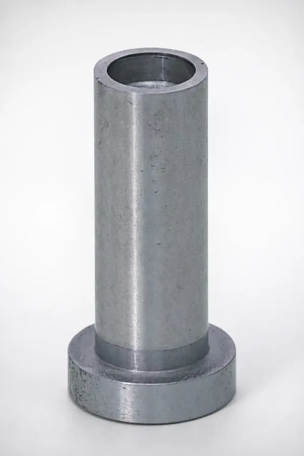
Timing lives or dies on a pin 1.5 to 3 mm across. The pin runs in a land bore held to ±0.01 mm, hardened and ground, and it closes onto a seat lapped to the pin itself. Too much clearance and melt tracks past the pin into the open side of the drop. Too little and the bore scores at the first hot cycle, because steel expands about 0.011 mm per meter per 10 °C, and a pin at 250 °C inside a bore at 90 °C finds its own clearance.
The shear edge is the part nobody specifies carefully enough. A land with a sharp, hardened edge at the gate severs the melt web every time the pin drops, keeping the tip clean. A rounded or soft edge leaves a filament that chars, falls into the cavity as a black speck, or welds the pin to its seat during a long stoppage. Inspect the edge at every tool pull and re-grind before the filament becomes a leak.
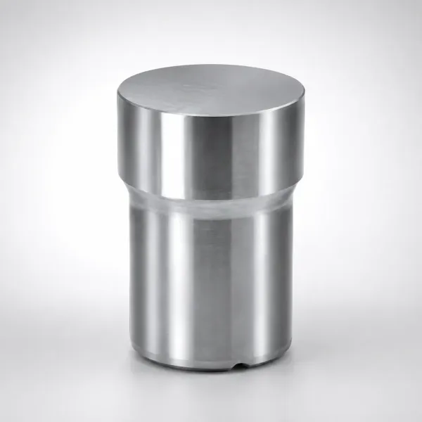
Melt pressure at the seat runs 150 to 400 MPa during pack. The actuator must beat that force across the pin's seat area plus seal friction, with margin, or the pin leaks exactly when the cavity is fullest. Pneumatic cylinders at 4 to 6 bar handle small pins; larger diameters or higher pack pressures push you to hydraulics or a stiff electric actuator. A pin that drools at pack is usually a force calculation problem, not a temperature problem.
Seat wear is the failure mode that ends the program early. A leaking seat shows first as a cold slug at the gate, then as flash in the shut-off, and it degrades quietly for tens of thousands of shots. The diagnosis sequence is in the hot runner leak troubleshooting guide, and the fix is a re-lap or a seat insert change scheduled the same week it is found.
Building the Controller Program
A valve gate controller stores the program as a profile per gate: open time, close time, and on an electric drive, an optional velocity curve between the two. Times are keyed to start of injection, on a 0.05 s grid, so every entry is a multiple of one slot. Build the profile from the fill map, run it cold with the tool open to verify actuator feedback matches the command, then load it for the trial.
Keep the profile readable. Gates numbered in flow order, delays named rather than buried in offsets, one revision log line per change with date and reason. Programs drift the way dies do: someone trims 0.05 s during a night shift, the cosmetic defect returns two months later under a new process engineer, and nobody can reconstruct what changed. The revision log is the cheapest insurance on the tool.
Validate the finished system against its own program, not against the first good parts. Hot runner validation covers the thermal and leak side. The sequencing side needs 30 to 50 consecutive shots with switch-over times recorded from controller feedback, plus a part weight chart across the same run. The program is proven when the recorded open and close times sit inside 0.05 s of the profile on every shot and the weight spread holds near ±0.3 percent.
Defects From Bad Timing
Sequential gating creates its own failure modes, and each one points at a specific timing error. Learn the three signatures and you can diagnose a program from a rack of bad parts.
Diesel burn marks the last gate to close. If the final front sweeps air into the corner behind the last-opened gate and that gate is still feeding, the trapped volume compresses against the incoming melt and ignites the gas. The burn sits at the terminus of the longest path, on a fixed spot, shot after shot. The fixes are a longer delay on the offending gate so the corner arrives pre-wetted, deeper venting at the last-fill point, or a slower final section. This is the same physics as a conventional air burn, but the timing makes it reproducible, which also makes it fixable.
Flash at an open gate is a pack-phase error. If a pin is still lifted when holding pressure arrives, melt squeezes around the gate land into any path the clamp allows, and the witness shows as a fin at the gate or a leak at the drop interface. Flash that appears only on one gate, on every shot, is a close-time error of 0.1 to 0.5 s, not a clamp problem. Move the close earlier into the pack tail by one or two slots and the fin disappears.
Jetting through an early gate happens when a pin lifts into a cavity region that is still empty. With no melt ahead of it and no wall to bounce off, the stream shoots across open space, freezes as a snake, and the next front engulfs it as a cold inclusion or a swirl. The gate opened before the neighbor's front arrived; a 0.05 to 0.10 s delay, or resequencing that gate behind its neighbor, removes it. The conventional jetting controls in the gate design guides help, but the root cause here is program order.
The Economics of Sequential Gating
Sequential gating does not change cycle time. Fill still takes the same 1.6 to 2.0 s, pack and cooling are untouched, and the actuation itself costs under 0.1 s inside the shot. The money moves on the scrap line and the capability line, so run the math on rejected parts rather than on output.
On a Class A automotive panel, cosmetic weld line rejects on a parallel-fill tool typically cost 1 to 3 percent of production. A correctly sequenced program holds the fronts off the visible faces and pushes cosmetic scrap below 0.5 percent, and the part weight spread near ±0.3 percent trims the dimensional rejects that ride with runner freeze drift. At 300,000 pieces a year, that swing is 1,500 to 7,500 parts recovered, before counting the sorting labor and the premium freight that follows a launch miss.
Against that, the valve gate system costs one actuator, one cartridge and one zone per gate, and a professional setup takes a filled map, a sensor plan and one or two trial days. That trial time is where most programs are won or lost, and it belongs in the project plan from the RFQ stage, the same way hot runner system selection and the mold-flow review do. A tool shop that schedules valve gate commissioning as an afterthought pays for it in scrapped pilot volumes.
Sequential Valve Gating FAQ
Q1. What open delay should I start with between valve pins?
30 to 80 ms between successive gates on a 0.05 s controller grid, with the sequence starting at 5 to 15 percent fill. Those are the actuator and resolution bands; the fill curve, not a rule of thumb, picks the exact slot for each gate.
Q2. When does the next gate open during the fill?
When the previous melt front has covered 60 to 80 percent of its flow path. Earlier leaves two live fronts to fold together mid-part; later lets the trailing front hit a boundary that already froze against cool steel.
Q3. How tight must switch-over timing hold in production?
Inside 0.05 s of the programmed profile on logged actuator feedback, shot after shot. A wider drift band means the fill pattern is being set by hydraulic variation, and the weld line will wander with it.
Q4. Does sequential gating change cycle time?
No. The fill, pack and cooling durations stay the same, and pin actuation adds under 0.1 s inside the shot. The benefit is quality: weld lines relocated off cosmetic faces and part weight held near ±0.3 percent.
Q5. Why is there a burn mark at my last gate?
The final front is sweeping air into the corner behind the last-opened gate and compressing it against incoming melt, a classic diesel burn. Add one or two 0.05 s slots of delay to that gate, or deepen the vent at the terminus, before touching melt or mold temperature.
The Bottom Line
Sequential valve gating is a fill-pattern program written in 0.05 s slots: sequence starts at 5 to 15 percent fill, each gate opens 30 to 80 ms behind the last, the next pin lifts when its neighbor's front covers 60 to 80 percent of the path, and the last gate closes inside the pack tail with switch-over logged inside 0.05 s. Hold those numbers and weld lines land on ribs instead of gloss faces, part weight holds near ±0.3 percent, and cosmetic scrap falls from 1 to 3 percent to under 0.5 percent on Class A parts without touching cycle time.
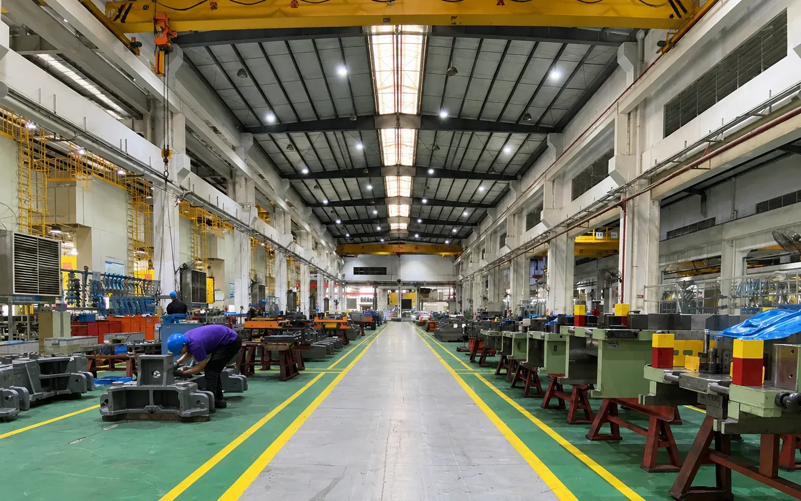
DieStrike builds and proves valve gate tooling to IATF 16949 with ±0.005 mm mold accuracy, ±0.002 mm on EDM and jig-grinding, HRC 62 maximum heat treatment, 120+ machines and DFM review before steel. Injection mold lead times run 2 to 5 weeks with standard components in 3 to 7 days, and T1 trials on automotive Class A programs are scheduled against the fill map so the first shots already carry a sequenced program.
KEEP READING
Related Reading
How to Troubleshoot Hot Runner Leaks
Seat wear, drool and the pressure tests that find a leak before it scraps parts.
Read articleArticleHow to Reduce Weld Lines: Gates, Ribs and Temperature
The five levers that move a weld line from visible and weak to hidden and strong.
Read articleArticle7 Gate Design Best Practices
Gate type, size and placement rules that decide fill pattern before any timing does.
Read articleIndustryAutomotive Molds and Dies
IATF 16949 tooling for Class A trim, connectors and underhood parts with tier-1 programs.
View industryNEXT STEP
Ready to Start Your Mold?
Send us your element dimensions or part numbers — our team responds within 24 hours with pricing and lead time.

Written by
Ray ChanMold Buyer's Guide Author · Precision Mold Manufacturing Specialist. Ray helps global importers, distributors and OEMs source factory-direct molds and mold parts.