
How to Specify Core Pins for Medical Mold Tooling
Table of Contents
One seized core pin can stop a validated medical mold mid-run. The batch in the press gets quarantined, the process validation file gets reopened, and an audit finding lands on the next ISO 13485 surveillance visit. Published industry analyses put the total cost of a medical device recall, counting notification, retrieval, and lost sales, in the millions of dollars per event. A 32-cavity mold for an insulin pen cartridge makes the arithmetic worse: one undersized pin produces 32 nonconforming parts per cycle, and the defect can run for thousands of cycles before a downstream gauge catches it.
Core pins are the steel rods that form the internal geometry of a molded part , the bore of a syringe barrel, the lumen of a catheter hub, the luer taper of an IV connector. In medical tooling they are small, ground to tight tolerances, and exposed to resins and cleanroom conditions that punish ordinary pin steel. Get the material, tolerance, finish, and support wrong and the failure shows up as a rejected lot, not a scrapped cavity. This guide walks through the specification decisions that keep those pins running inside a validated process.
The Snapshot
- ±0.005 mm is the standard ground diameter tolerance for medical core pins; precision pins are ground to ±0.002 mm (a DieStrike capability).
- HRC 50-58 is the typical working hardness band for stainless core pins; 440C sits at the top of that band.
- Ra 0.05-0.2 µm is the typical surface finish range for medical cavities and pins, with SPI A2/A1 polish for optical-grade bores.
- 20:1 is the practical ceiling for unsupported length-to-diameter ratio on slender pins; beyond it, add bushings or stepped support.
- 0.5-1° per side is the typical draft on long blind bores, applied in the pull direction.
Why Core Pins Matter in Medical Molds
Medical devices fail on function, and internal geometry carries most of the function. A syringe must deliver an accurate dose, so barrel bore diameter controls plunger seal interference. A catheter hub must pass a defined flow rate, so lumen diameter and surface finish set the pressure drop. An IV connector must seal against a mating luer, so the internal taper has to match ISO 80369-3 geometry. Every one of those features is formed by a core pin.
The tolerance chain is short. Pin diameter error becomes bore diameter error with no intermediate step. A 0.01 mm oversize on a 3 mm syringe barrel core raises the bore by the same amount. It changes plunger glide force and can trip a functional test at final inspection. A 0.02 mm undersize on a catheter lumen core can drop flow rate below the spec published on the device label.
Validation makes the stakes permanent. Once IQ/OQ/PQ is signed off, the mold becomes part of the device master record. Any change to pin material, coating, or geometry triggers a change assessment. A pin that wears past tolerance between validations is not a maintenance item , it is a nonconformance that must be documented, investigated, and dispositioned under 21 CFR 820.100.
Cleanroom and regulatory pressure add two more constraints. Medical molds are often stored and run in controlled environments where humidity cycles condense on steel. Ordinary tool steel pits and corrodes in that atmosphere, and the corrosion particles migrate into the molding process. That is why corrosion resistance is a specification driver, not a nice-to-have, for medical core pins.
The economics favor getting the spec right once. A precision stainless core pin with coating costs tens of dollars at most. A rejected lot, a failed audit finding, or a recall event costs orders of magnitude more. Pin specification is the cheapest quality control step in the program.
What Medical Core Pins Do
Core pins form the internal cavities of molded medical parts. Unlike ejector pins, which push the part off the core, core pins shape the part during fill and then release it at ejection. On many medical parts the same pin does both jobs. The distinction matters because a forming pin carries dimensional responsibility that a pure ejector does not.
Thin Bores and Tight ID Tolerances
The parts that stress core pins the most share three traits. Those traits are long thin bores, tight internal tolerances, and high cavitation. Catheter-related components run lumen diameters from roughly 0.4 mm to 2.0 mm, with wall sections under 0.5 mm typical. Syringe barrels hold bore tolerances of ±0.02 mm to ±0.05 mm typical so the plunger seal rides consistently. Insulin pen cartridges and pump reservoirs mold thin walls around a long central core, where the pin is the forming surface and main heat sink.
IV components combine all three pressures. Luer lock threads, drip chamber inlets, and spike shafts all form around cores with fine pitch details. The 6% luer taper defined by ISO 594 and ISO 80369-3 is ground directly into the pin. The pin's cone angle, roundness, and finish are then copied onto every molded part.
Thermal load is part of the job. A long thin core in a 32-cavity mold cycles between a 40 °C to 60 °C mold temperature swing every 15 to 30 seconds. The pin must shed that heat through its own cross-section or a cooling channel. The part around it cannot cool fast enough on its own. That is why medical core pins are specified with the resin's cooling behavior in mind, not just its flow.
Core pins also carry the demolding load on parts with deep internal features. Shrinkage pulls the molded bore tight against the pin, and the stripping force climbs with bore length and draft. The pin has to resist that force without flexing, without bending, and without tearing the bore surface.
Steel Selection for Medical Core Pins
Steel choice starts with the corrosion requirement. A mold that runs and stores in a cleanroom atmosphere sees moisture cycles, and stainless grades eliminate the pitting risk that bare H13 carries. That is why stainless core pins dominate medical tooling. H13 is reserved for high-wear, coated applications. Maraging covers pins that need dimensional stability under heat.
Steel Grade Comparison for Medical Core Pins
The table below compares the grades most often specified for medical core pins. Hardness values are typical ranges after heat treatment; verify the exact spec against the mill certificate and the drawing.
| Grade | Typical hardness | Corrosion resistance | Polishability | Typical use in medical molds |
|---|---|---|---|---|
| 440C stainless | HRC 56-60 | Good | Good to SPI B2, limited to A2 | Small pins where wear resistance beats polish |
| 420 stainless | HRC 48-52 | Good | Good to SPI A2 | Bores that need mirror finish over peak hardness |
| S136 / 1.2083 ESR | HRC 50-54 | Excellent | Excellent to SPI A1/A2 | Default for transparent and polished medical bores |
| Stavax ESR | HRC 50-54 | Excellent | Excellent to SPI A1/A2 | Large cores and high-cavitation tools |
| H13 (hot-work tool steel) | HRC 46-52 | Poor without coating | Good with nitriding | High-wear coated pins, high molding temperatures |
| Maraging 18Ni 300/350 | HRC 52-56 | Moderate | Good to SPI A2 | Long slender pins needing high strength and stability |
← swipe to scroll →
Each grade earns its place through a different trade. 440C delivers the highest hardness of the stainless group. That helps small-diameter pins resist wear on glass-filled medical resins. Its chromium carbides limit how fine a polish it will hold.
S136 and Stavax are both ESR-refined 420-class stainless steels. The ESR route removes carbide segregation. That is why they polish to SPI A1 and A2 with fewer pinholes.
H13 stays in the picture for high-temperature or high-wear service. Those pins get a PVD or nitrided coating to close the corrosion gap. Maraging 18Ni grades bring high strength with excellent dimensional stability during heat treatment. That matters for long slender pins. They would distort through a conventional quench-and-temper cycle.
For a fuller comparison of cavity and core steel choices, read our guide to medical-grade mold steel. The same material logic applies to pins, scaled down to the pin's smaller mass and faster thermal response.
Balance Hardness, Polish, and Corrosion
Three properties fight each other in a medical core pin. Higher hardness resists wear but often limits polish. Deeper polish reduces release friction but needs a clean, fine-grained steel. Corrosion resistance protects the process but can drop with certain coatings and heat treatments. The spec sheet has to state all three explicitly.
Hardness: HRC 50-58 Typical for Stainless Pins
The working hardness band for stainless core pins runs roughly HRC 50 to 58. 440C sits at HRC 56-60 typical, 420-class ESR grades at HRC 50-54 typical, and H13 at HRC 46-52 typical when used uncoated. Below HRC 50, a pin forming glass-filled or abrasive medical compounds starts to show tip wear and edge rounding within a few hundred thousand cycles.
Hardness is verified, not assumed. DieStrike runs hardness checks on pin material and finished pins, and the values go on the inspection report with the drawing tolerance. A Vickers reading converted to HRC is the standard method for small cross-sections where a direct Rockwell indent would distort the pin.
Polish: SPI A2/A1 for Optical Bores
Polish level is specified with SPI surface finish codes. SPI B2 (600 grit) suits functional bores where release matters but cosmetics do not. SPI A2 (6000 grit) and A1 (3 µm diamond) are typical for lumens and bores that must be mirror-smooth for flow, sealing, or cleanability. A polished pin releases better, wipes cleaner between cycles, and leaves fewer witness marks on transparent resins.
Polish direction matters on cores. Final polishing strokes run along the pull direction, so any residual tool marks do not create undercut-like ridges that drag during ejection. On a long bore, a cross-polished surface raises stripping force noticeably.
Corrosion: The Cleanroom Constraint
Medical molds are cleaned, stored, and often run in controlled environments. Humidity cycles can condense on a cold mold face. Non-stainless pins in that environment develop surface pitting, and the pits hold resin residue that becomes a contamination source. Stainless grades close that risk, which is why corrosion resistance is a stated requirement on medical pin drawings rather than an implicit property.
If the pin must be coated, check that the coating does not undo the steel's corrosion resistance. Some PVD processes can leave the substrate vulnerable at the interface. Specify a coating applied and tested to the same corrosion standard as the base steel.
Diameter Tolerance and Surface Finish
The bore dimension of the part is a direct copy of the pin diameter, so pin tolerance flows straight into part tolerance. Medical drawings commonly call out bore diameters at ±0.02 mm to ±0.05 mm. That leaves a tight budget for the pin itself, and grinding is the only practical way to hit it on hard steel.
Ground Diameters: ±0.005 mm Standard, ±0.002 mm Precision
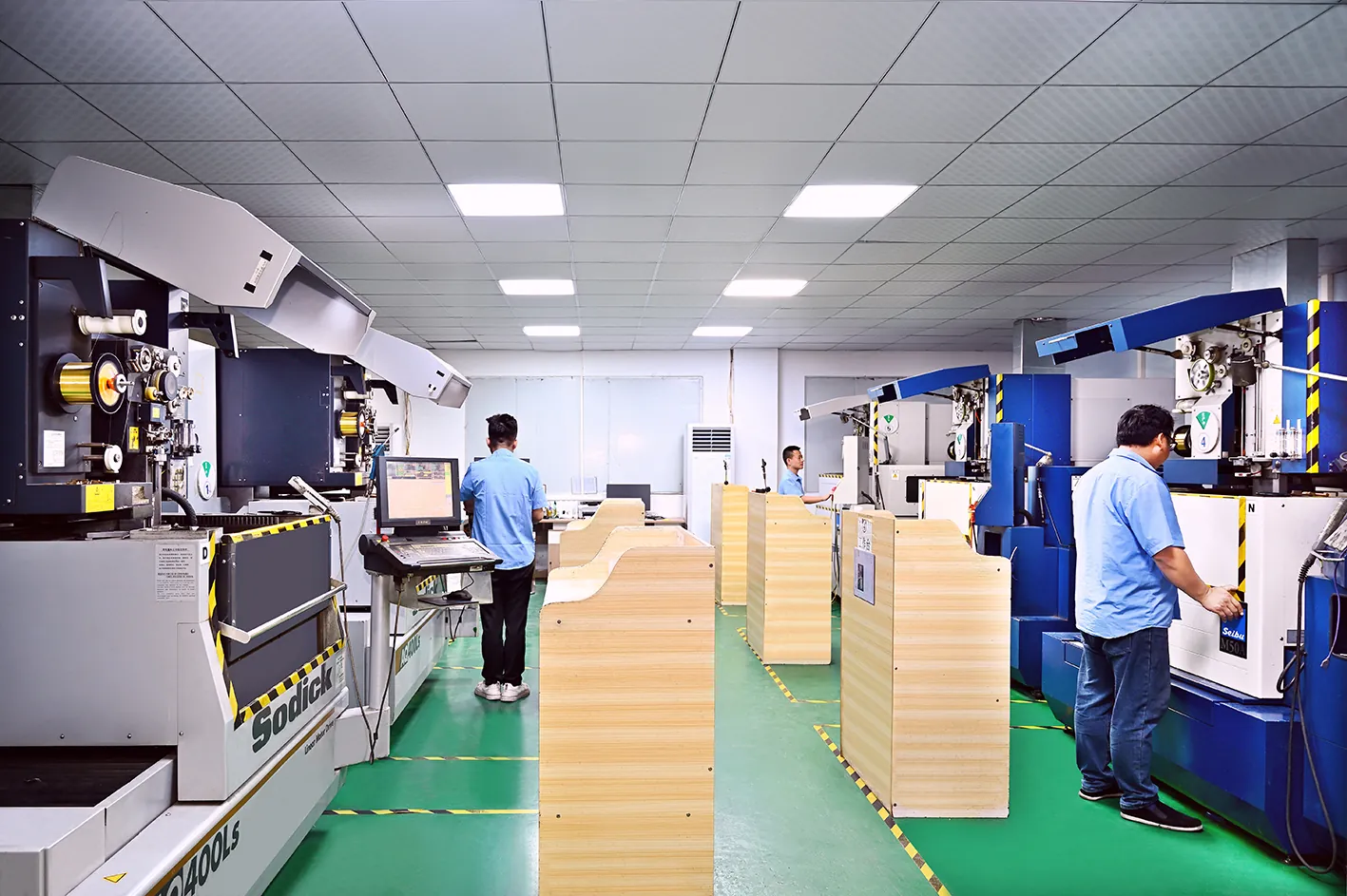
Core pins for medical molds are typically ground to ±0.005 mm on the forming diameter as the standard class. Where the application demands it , luer tapers, syringe bores, precision lumen IDs , pins are ground to ±0.002 mm. DieStrike holds that precision class on standard and custom pins, verified on a CMM or laser micrometer at the finish size.
Grinding sequence matters. Rough OD grinding, then heat treatment, then finish grinding to size, then lapping or polishing the forming length. Each pass removes a fraction of the stock so the finish pass sees a stable, round blank. Centerless grinding handles the long straight OD; jig grinding locates stepped diameters and shoulders to the drawing's positional tolerance.

Surface finish on the forming length is specified separately from diameter. Medical cavities and pins run Ra 0.05 to 0.2 µm typical, with SPI A2/A1 polish equivalent on bores that carry fluid or sealing function. The finish spec should name both Ra and the SPI code, because two different inspection methods can disagree on the same surface.
Verify With the Right Instrument
Diameter verification is a measuring instrument decision, not a judgment call. Micrometers read the OD at the measured point but say nothing about taper along the length. A laser micrometer or CMM profile scan catches taper, ovality, and shoulder positions. For bores, air gauging or CMM probe passes confirm the formed ID matches the pin. The verification report should attach to the pin's batch record.

If your program holds ±0.002 mm anywhere, the pin plan, machining route, and inspection method must be designed together from the start. The process discipline behind that tolerance class is covered in our guide to holding ±0.002 mm.
Draft Angles and Long Bore Geometry
Draft is the angle that lets a molded bore slide off its core. On short features, zero draft can still eject. On long bores, zero draft is a recipe for tearing the part or bending the pin. Medical cores that form deep bores typically carry 0.5° to 1° per side of draft, applied in the pull direction.
The tension is real: draft changes the bore size along its length. A 10 mm long bore at 0.5° per side grows about 0.17 mm in diameter from root to mouth. If the print calls the bore a constant diameter, the draft has to live inside the tolerance, or the design must accept a tapered bore. That negotiation happens on the drawing before steel is ordered.
Through-holes are the exception. A bore that goes all the way through is formed by two opposing cores, or by a core and a cavity detail. Neither side needs draft, because there is no closed end to release. Blind bores, counterbores, and blind threads always need draft on the closed end.
Long cores also need a plan for how the part comes off. Stepped cores, where the pin diameter changes in stages, reduce the contact area and the stripping force. Tapered cores for luer geometry are ground to the exact cone angle, and the polish follows the cone. The pin drawing should state draft per side, not total included angle, to avoid a 2× ambiguity at inspection.
When bore length approaches ten times the diameter, consider splitting the geometry. A two-piece core, or a core with an ejector sleeve around it, keeps stripping forces manageable. It also gives the tool a replaceable wear surface. That avoids remaking the whole core assembly.
Venting and Ejection for Thin Cores
Air trapped at the end of a blind bore is a classic medical mold defect. The resin compresses the air pocket, burns it, and leaves a short shot or a charred spot inside the bore , exactly where inspection looks. Thin cores also resist heat transfer, so trapped air combined with a hot pin tip produces carbon deposits that contaminate the next parts.
Venting the Blind Bore
Vent slots ground along the pin OD are the standard answer. A slot depth of 0.01 to 0.03 mm typical lets trapped air escape to atmosphere or to a vented bushing. The molded bore material fills the slot gap with thin flash. Downstream trimming removes that flash. Vent location goes at the end of the fill path, which on a core pin means the far end of the bore.
Where the bore geometry blocks a straight vent slot, other options exist. Vented bushings with cross-drilled channels, sintered vent inserts, and stepped core construction all work. Each step creates a natural vent path. Each option changes the pin plan, so venting is designed before the pin order, not after first trial.
Ejection From the Core
Ejection force on a medical core comes from shrinkage grip plus any undercut or texture on the bore. For short pins, the ejector plate stroke alone pulls the part off. For long or grippy cores, the pin works with an ejector sleeve or a stripper ring at the bore mouth. The release force then spreads across the part. It does not concentrate at the pin tip.
Pin-to-sleeve fit is part of the spec. The clearance between a forming core and its surrounding ejector sleeve typically runs 0.01 to 0.02 mm. Too tight, and the sleeve binds on the pin. Too loose, and flash grows between them and produces a witness ring inside the bore.
After ejection, the pin surface has to stay clean. Residue on the forming length becomes a dimensional defect on the next cycle. That is why medical pins are specified with release-friendly finish and, where needed, a low-friction coating that keeps the bore clean cycle after cycle.
Stop Flex and Buckling
A long slender pin behaves like a column under compression. Injection pressure pushes the melt around it, and ejection force pulls along it. If the pin is too long for its diameter, it flexes under fill pressure, bending the bore, or buckles under ejection force, snapping the tip. Both failures scrap the mold run.
The 20:1 Unsupported Length Rule
The practical ceiling for unsupported length-to-diameter ratio on core pins is about 20:1. A 1.0 mm diameter pin is safe unsupported to roughly 20 mm. Beyond that, the pin needs support along its length or a bigger diameter. This is a working rule, not a law , the real check is Euler buckling under the expected force, and the safety factor should be at least 2 against the peak ejection force.
Forcing a 40:1 pin into a design because the bore demands it is the most common core-pin failure cause in medical molds. The alternative is a stepped core: larger diameter in the support length, forming diameter only at the tip. Stepping adds stiffness where it counts and keeps the bore geometry unchanged.
Support Bushings and Puller Pins
Support bushings are the standard fix for long pins. A hardened bushing rides along the pin in the non-forming zone, guiding it and resisting the lateral component of fill pressure. Bushing material and fit are part of the pin spec , a soft bushing wears, a tight bushing binds. Typical running clearance between pin and bushing is 0.005 to 0.01 mm.
Puller pins take a different job: they hold the molded part on the core side during mold opening, preventing it from sticking in the cavity. On medical parts with shallow internal features, a puller pin does this job. A small undercut nose holds the part on the core until the ejector system releases it. Puller pin geometry and its release force are documented on the drawing, because the undercut nose is a formed feature that inspection checks.

The support plan is decided at mold design, not at pin sourcing. If the mold layout cannot fit a bushing, the pin diameter or the number of cavities has to change. Medical mold programs that skip this step pay for it in first-trial rework.
Heat Treatment and Coating Options
Heat treatment sets the pin's strength, and coating sets its surface behavior. Both are spec items with measurable acceptance criteria. Medical pin drawings should state hardness range, heat treatment route where it affects the part, and coating type with thickness.
Heat Treatment Routes
Stainless pins are through-hardened and tempered to the specified HRC band. ESR grades like S136 and Stavax respond predictably to vacuum hardening. Distortion stays minimal, which matters below 2 mm diameter where 0.01 mm of distortion eats the tolerance. Maraging pins skip the quench entirely. They age-harden at moderate temperature, which is why they stay dimensionally stable.
H13 pins are hardened, tempered, and often nitrided for wear. Nitriding lifts the surface to roughly 900 to 1100 HV while the core keeps its toughness. Nitrided H13 pins resist abrasive medical compounds but still need a coating or plating to close the corrosion gap in cleanroom service.
PVD and DLC Coatings
PVD coatings in the 2 to 4 µm range, most often TiN or TiAlN, cut wear on glass-filled and abrasive medical resins. They also reduce the galling that starts between fresh steel surfaces. DLC (diamond-like carbon) coatings run thinner, roughly 1 to 3 µm, and bring two things medical molding values: low friction for release and a dense, inert surface that wipes clean.
Coating decisions interact with geometry. Coatings follow corners and tips at a reduced thickness, so a sharp pin tip sees less protection than the flank. And a coated pin that later needs re-polishing must be stripped and recoated, never polished through the coating. Put the coating in the maintenance plan, not just the purchase order.
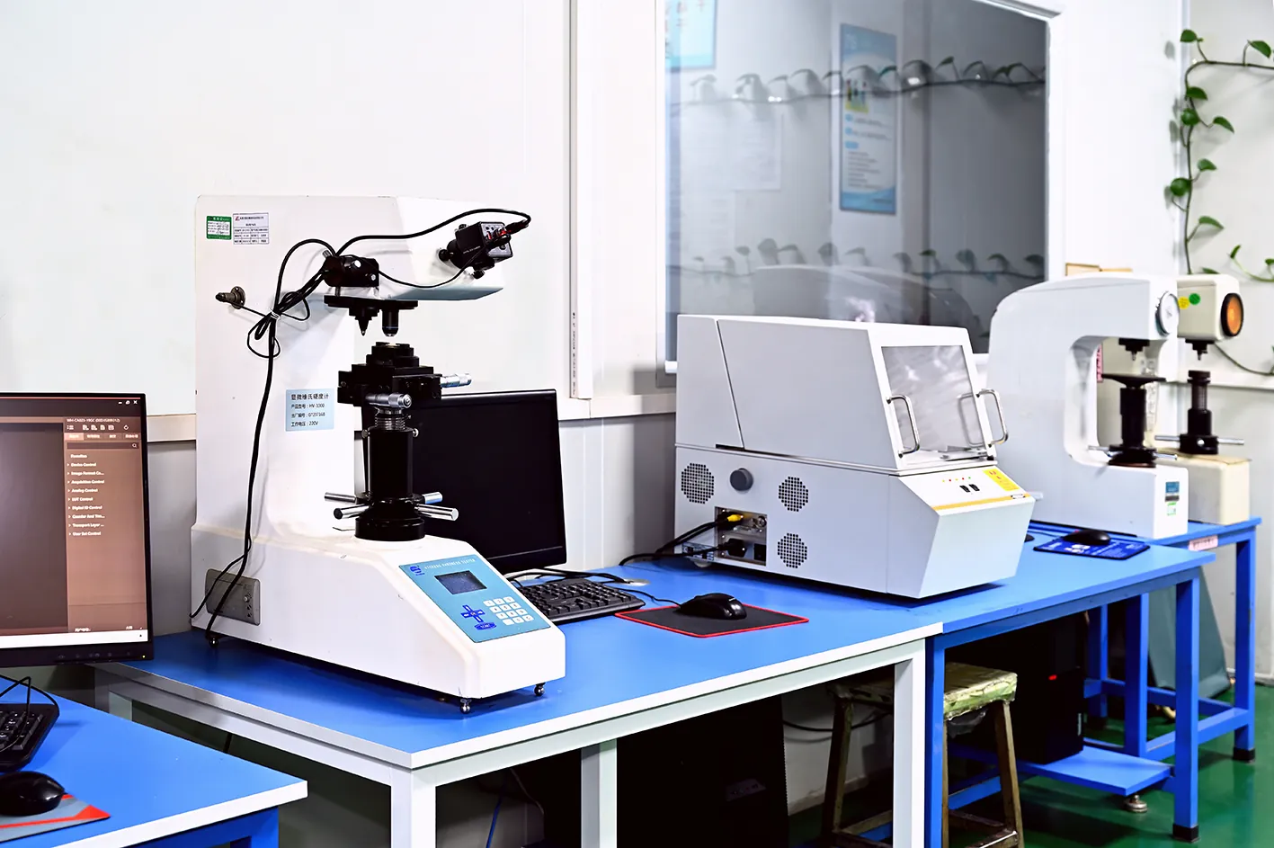
Hardness and coating thickness are verified and reported. DieStrike's inspection record includes the hardness reading and, where the coating is functional, film thickness. The report travels with the pin lot, so the validation file can reference it during IQ/OQ/PQ.
Cleaning Protocols and Validation Linkage
A medical core pin is delivered as a controlled item, not a commodity part. The delivery package should include the material certificate, hardness report, dimensional inspection report, and a cleaning and packaging record that matches the mold's cleanroom class. Without those documents, the pin cannot be accepted into a validated mold without a deviation record.
Cleaning and Passivation
Stainless pins are cleaned after final polish and coating to remove grinding media, lapping compound, and handling residue. Ultrasonic cleaning with a validated cycle removes particulate from threads, flats, and stepped shoulders. Passivation of stainless pins per ASTM A967 restores the chromium oxide layer. Grinding and polishing disrupt that layer. Passivation is a documented step for cleanroom service.
Packaging is part of the spec. Pins ship in sealed, labeled containers that identify grade, lot, and part number. The goal is a pin that goes from the container to the mold with no additional cleaning step and no ambiguity about what it is.
Validation Linkage: IQ/OQ/PQ and Material Certs
Core pins enter the validation chain at three points. Material certification (EN 10204 3.1 or mill certificate with chemistry) supports the Design Input review. Dimensional inspection reports support the FAI during Installation Qualification. And the in-process hardness and finish records support the process capability checks during OQ and PQ.
ISO 13485 and 21 CFR 820 expect traceability: the pin's lot, the heat number, the coating batch, and the inspection records should be linkable. A pin that wears or fails after validation has to be traced back to its material and treatment history to close the corrective action loop. Specify the documentation at order time, and it exists when the auditor asks.
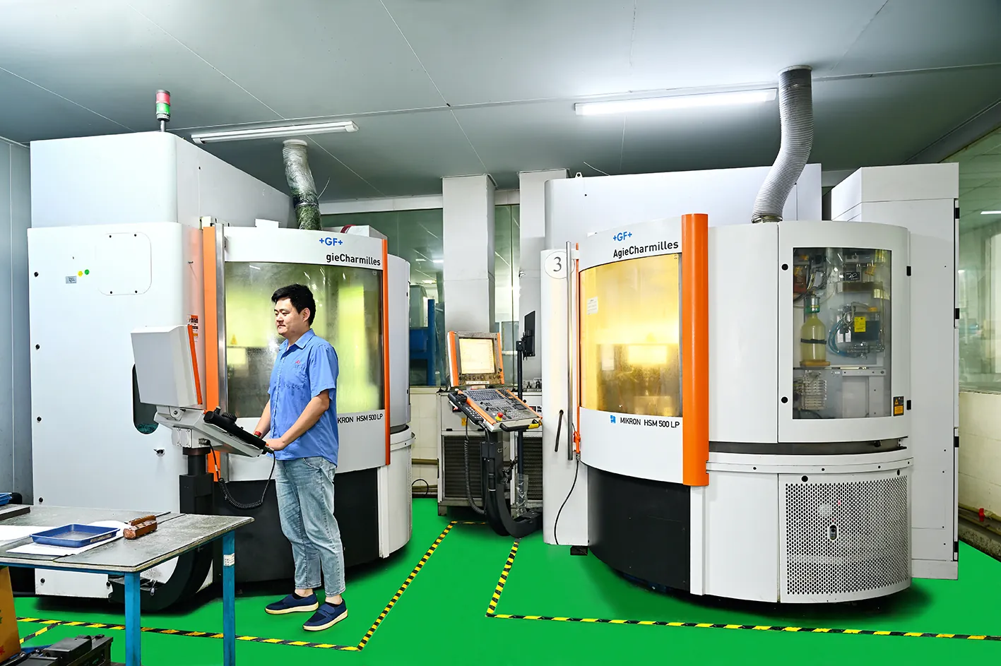
DieStrike runs its mold shop under IATF 16949 and ISO 9001 quality systems. The floor carries 120+ machines. Precision components go to customers including TE Connectivity, Amphenol, Luxshare, and Dongshan. The same documentation discipline that serves automotive connector programs applies to medical pin lots: full inspection reports, material certificates, and batch traceability on request.
FAQ
Q1: What is a core pin in an injection mold?
A core pin is a hardened steel rod that forms the internal geometry of a molded part , bores, lumens, tapers, and undercuts. In medical molds it shapes the bore of a syringe, the lumen of a catheter hub, or the taper of a luer connector. It then releases the part at ejection.
Q2: What steel should medical core pins use?
Stainless grades dominate because cleanroom moisture corrodes plain tool steel. S136 or Stavax (ESR 420-class) are the typical default for polished medical bores. 440C suits small pins needing peak hardness. H13 with coating handles high-wear or high-temperature service. Maraging covers long slender pins that must stay dimensionally stable.
Q3: What tolerance can core pins be ground to?
±0.005 mm on the forming diameter is the standard ground class for medical pins. Precision pins are ground to ±0.002 mm, which DieStrike holds as a production capability on standard and custom core pins.
Q4: When do core pins need a coating?
When the resin is glass-filled or abrasive, when the pin sees high cavity pressure, or when release friction drives defect rates. TiN/TiAlN PVD coatings in the 2 to 4 µm range cut wear; DLC at 1 to 3 µm adds low friction and clean release. Uncoated stainless pins suit short-run, low-wear programs.
Q5: Why do core pins break, and how do you prevent it?
They break from buckling under ejection force or flexing under fill pressure when the unsupported length exceeds about 20 times the diameter. Prevent it with stepped cores, support bushings, and larger diameters in the support zone. Run a buckling check with a safety factor of at least 2 against peak force.
Q6: What documentation should the mold maker provide with medical core pins?
Material certificate with chemistry, hardness report, dimensional inspection report, coating thickness where applicable, and cleaning/packaging records. Those documents link the pin to IQ/OQ/PQ and satisfy ISO 13485 traceability during audits.
The Bottom Line
Core pins are the smallest line item in a medical mold and the fastest path to a rejected lot. The specification is short but complete.
It names the corrosion-resistant steel grade, the HRC hardness band, and the diameter class: ±0.005 mm standard, ±0.002 mm for precision bores. Finish is set at Ra 0.05 to 0.2 µm with the SPI code. Draft is applied per side, venting is planned into the bore, and support is designed for pins past 20:1. The coating is chosen for wear and release, and the documentation package is attached at order time.
Every one of those decisions maps to a number on a drawing and a line in the validation file. Get them right at specification and the mold runs inside its validated window; get one wrong and the audit finds it. Start the spec from the part's internal geometry. Work the pin plan through material, grinding, support, and coating. Confirm the tolerance class against the shop's measured capability.
If you are setting up a new medical program, the practical entry point is the forming geometry itself. Work through the bore dimensions, the resin, and the validation requirements first, then match the pin grade, tolerance, and finish to them , and let the drawing, not the catalog, carry the final numbers. DieStrike manufactures standard and custom core pins to drawing, including the ±0.002 mm precision class, with inspection reports that drop straight into a validation file.
NEXT STEP
Ready to Start Your Mold?
Send us your element dimensions or part numbers — our team responds within 24 hours with pricing and lead time.

Written by
Ray ChanMold Buyer's Guide Author · Precision Mold Manufacturing Specialist. Ray helps global importers, distributors and OEMs source factory-direct molds and mold parts.