
Nitriding vs PVD Coatings for Mold Steel: Which Surface Treatment When
Table of Contents
A 16-cavity PBT connector mold ships, runs 40,000 shots, and comes back with 0.15 mm of wash on a gate insert corner. The core pins are scored, the slides carry smeared resin, and the molder blames the material. In most of those cases a bare HRC 48 core face met a 30% glass-filled resin with no surface treatment at all. A CrN layer costing 60-120 USD per part would have carried the same insert past 500,000 shots.
Surface treatment is the cheapest lever on mold life, and the easiest one to specify wrongly. A 0.1-0.3 mm nitrided case or a 2-5 µm PVD film can multiply tool life by 3-10x on abrasive or adhesive resins. The same layers can also wreck a tool. Wrong process temperature or film thickness can also wreck a tool. A 5-15 µm dimensional change becomes a flashing shut-off. A coated texture no longer matches the approved SPI sample.
This guide compares the processes shops actually specify. That means gas nitriding, ion (plasma) nitriding and PVD coatings such as CrN, TiAlN and TiCN. DLC is the low-friction fourth option, and every number below belongs on a purchase order. Temperature, case depth, compound layer thickness, growth allowance, substrate hardness, cost band and acceptance test all decide whether the treatment pays back.
The Snapshot
- Gas nitriding runs 500-560 °C for 20-60 h. It builds a 0.1-0.3 mm case at 900-1,200 HV, topped by a 5-15 µm compound (white) layer.
- Ion nitriding holds 480-560 °C for 10-30 h. It controls the compound layer from 0 to 8 µm, with better uniformity on deep ribs and small cores.
- Nitriding grows mold steel 5-15 µm per side. Pre-grind with that allowance or shut-offs will flash once the tool reaches production temperature.
- PVD films are 2-5 µm thick: CrN at 1,750-2,000 HV, TiCN at 2,800-3,200 HV, TiAlN at 2,800-3,300 HV. Substrate hardness must sit at HRC 54-60 for adhesion.
- DLC delivers a friction coefficient near 0.1 at 1-3 µm, but most hydrogenated grades soften above 250-350 °C, which rules out hot runner gate areas.
Why Surface Treatment Decides Mold Life
Mold failure starts at the surface. Roughly 80% of tooling failures begin as surface damage: abrasive scratching, adhesive pickup, corrosion pitting or heat checking. A hardened core body at HRC 48-52 resists bulk deformation. The contact zone still sees local pressures above 1,000 MPa. Sliding speeds at the gate and the slides reach 0.2-1.5 m/s.
A treated surface changes three numbers at once. Surface hardness rises from HRC 50 to the 900-1,200 HV band, which is roughly HRC 67-72 equivalent. Friction drops, sometimes from 0.3-0.5 to 0.1-0.2 with DLC. Chemical inertness improves, so a PVC melt releasing hydrogen chloride at 170-200 °C cannot attack the tool face the way it attacks bare 1.2343.

Treatment is not a substitute for steel selection. A nitrided case sits on a soft core, and case hardness means nothing if the substrate collapses under 1,500 bar cavity pressure. Coatings behave the same way. A 3 µm CrN film on a HRC 45 substrate will spall within 20,000 shots. The film follows every plastic deformation of the steel underneath. Substrate first, surface second. If the base steel is still open, the heat treatment guide covers hardness targets before any coating decision.
Sequencing decides the result. Nitriding happens after rough machining and stress relief, then finish grinding and polishing follow. PVD happens last, after final polish, because a 2-5 µm film reproduces the surface beneath it. Coat a Ra 0.8 µm face and you get a rough, friction-generating coating. Coat a Ra 0.02 µm mirror and you get a smooth film that still changes gloss slightly. Order of operations, not the coating brand, drives most coating failures in the field.
Gas Nitriding vs Ion Nitriding
Nitriding diffuses nitrogen into the steel surface between 480 and 570 °C. No quenching follows, so distortion stays small and the part keeps its core toughness. The two production routes differ in how the nitrogen reaches the surface, and that difference drives cost, uniformity and the compound layer you can specify.
Gas nitriding. Parts sit in a sealed retort with ammonia at 500-560 °C for 20-60 h. Cycle time depends on target case depth, roughly 0.005-0.01 mm per hour at typical temperatures. A 0.2 mm case needs 30-45 h. Gas nitriding suits H13, 1.2343, 1.2344, nitriding-grade P20, S136 and 420 stainless, and it handles mixed batches at low unit cost. It also loads the whole part, including surfaces you may not want hardened.
Ion (plasma) nitriding. A glow discharge ionizes a nitrogen-hydrogen mix at 480-560 °C and bombards the surface. Cycle time is shorter at 10-30 h for the same case depth band. Gas consumption is lower, and masking is simpler. The plasma only needs a visible line of sight. The sputtering action also strips the passive chromium oxide layer on stainless grades. Grades 420 and 1.2083 therefore nitride without an extra activation step.
Compound layer control is the deciding factor. Gas nitriding typically leaves a 5-15 µm white layer that is hard and brittle. Ion nitriding lets you dial the compound layer from 0 µm (diffusion only) up to about 8 µm by adjusting gas mix. Impact-loaded cores and punches usually want 0-3 µm. Corrosion service wants 5-10 µm. High-precision shut-offs want a thin layer that can still be ground back.
Geometry decides uniformity. Gas nitriding is a furnace process, so small holes and blind recesses nitride as long as the gas can reach them. In practice, features under 1 mm diameter and holes deeper than 10x diameter come out shallow or bare. Ion nitriding needs line of sight, which favors uniform coverage on slender core pins and deep ribs but leaves shadowed pockets untreated.
Case Depth, White Layer and Growth
Case depth is the distance from the surface to the point where hardness falls back to core values, measured on a polished cross-section. For molds, three bands cover almost every application. Light cases of 0.05-0.08 mm suit ejector pins, small core pins and delicate shut-offs. Standard cases of 0.10-0.20 mm cover most cores, slides and gate inserts. Heavy cases of 0.25-0.35 mm go on hot work cores and high-wear stamping tools where abrasive filler content runs above 30%.
Deep is not automatically better. A 0.3 mm case on a 4 mm core pin leaves a thin, soft core. Impact from ejection then cracks the case, and the crack propagates along the case-core boundary. For pins under 6 mm diameter, stay at 0.05-0.10 mm and keep the core above 60% of the section. Case depth specification should state total case depth per ISO 18203 and the hardness criterion used, typically core hardness plus 50 HV.
Dimensional growth must be planned, not discovered. Nitrogen diffusion expands the lattice. Typical growth figures run 5-15 µm per side, or 10-30 µm on diameter. A core pin ground to 8.000 mm can come back at 8.012-8.030 mm and no longer enter a 8.005 mm hole. The standard practice is to pre-grind 10-20 µm undersize, nitride, then finish grind if the tolerance band is tighter than 0.02 mm. For tight fits, leave nitriding before the final grinding operation.

White layer removal is a decision, not a default. The 5-15 µm compound layer is 900-1,200 HV and brittle. On impact-loaded edges, grind or polish 5-10 µm off the surface to expose the tougher diffusion zone. On corrosion service, keep the white layer because it is the barrier against chloride and acid attack. Grinding it away removes the best corrosion protection the process offers.
Never nitride surfaces that need later welding. A nitrided layer must be fully stripped before any laser or TIG repair, and stripping means grinding back 0.05-0.2 mm or a full anneal. Shops that nitride everything at the end of a build often pay for it at the first repair. Mark non-nitrided zones on the drawing and mask threads, dowel bores and shut-offs with 0.005-0.01 mm fits.
PVD Coatings: CrN, TiAlN and TiCN
Physical vapor deposition deposits a 1-5 µm ceramic film in a vacuum chamber at 180-500 °C. The film is thin, hard and dimensionally almost neutral. It fits mold components held to ±0.005 mm, where nitriding growth is not acceptable.
Coating selection follows the wear mode. CrN at 1,750-2,000 HV offers the best corrosion resistance. Its friction coefficient against steel runs 0.3-0.4. It fits PVC and halogenated flame-retardant resins that release acids. TiCN at 2,800-3,200 HV resists abrasive wear from glass-filled grades and holds up on gate inserts and slides. TiAlN at 2,800-3,300 HV adds oxidation resistance to roughly 700-800 °C, useful in hot runner nozzles and hot work areas. All three are applied at 2-5 µm, with 3 µm as the practical minimum for a working wear film.
Substrate hardness sets the ceiling. PVD films are hard but thin, so they cannot carry load without support. The accepted window is HRC 54-60 for tool steel molds. Below HRC 52, the substrate deforms under contact pressure and the film cracks at the deformation edges. Hardened H13 at HRC 54-56 is the classic PVD substrate. Pre-hardened P20 at HRC 30-34 is a poor one, unless the loaded areas are hardened inserts.

Shadowing limits coverage. PVD is a line-of-sight process. A hole that is deeper than 2-3x its diameter receives a thin or missing film on the lower walls. Sharp edges get thinner coverage because the film grows from one direction, and the corner loses about 30-50% of its thickness. Features to watch include deep ribs, narrow slots below 1 mm, blind holes and undercut pockets. If the wear zone sits inside such a feature, nitriding covers it where PVD cannot.
Adhesion is a process outcome, not a guarantee. A clean, polished, correctly hardened surface holds a film for 500,000+ shots. Oil, rust, EDM recast layer and residual polish compound cause local spalling within the first few thousand shots. Any part going to PVD should leave the EDM with the recast layer removed. Grind or soft polish 0.01-0.02 mm, then handle the part with gloves.
DLC and Low-Temperature Options
Diamond-like carbon is a 1-3 µm amorphous film with a friction coefficient between 0.05 and 0.2 against steel and most resins. That low friction is the whole point. It cuts the shear stress that drives adhesive pickup. Galling on stainless inserts, aluminum die casting shot sleeves and sticky TPE slides drops by an order of magnitude.
Hardness depends on the grade. Hydrogenated a-C:H films run 1,500-2,500 HV. Tetrahedral ta-C grades reach 4,000-8,000 HV at higher internal stress and higher cost. Either way, DLC needs a hard substrate. The film is 1-3 µm thick, so any substrate yielding below HRC 50 deforms and the film cracks. The usual substrate window is HRC 55-62.
Temperature is the hard limit. Hydrogenated DLC starts losing hydrogen above 250-300 °C and graphitizes, which removes the low-friction benefit. ta-C holds to roughly 400-500 °C. A hot runner gate insert running at 280-320 °C melt temperature with poor cooling sits right at that edge. Specify DLC for cold-side wear surfaces, not for hot manifold components.
Low-temperature PVD fills the gap. Chambers running at 180-250 °C coat steel that was tempered at 200-250 °C. That includes nitrided and some pre-hardened parts. A 450-500 °C cycle would soften them below the HRC 54 adhesion threshold. These low-temperature cycles trade some film density and adhesion for temperature safety, so they suit precision inserts rather than high-impact punches.
Ferritic nitrocarburizing is the fourth process. Adding carbon to the nitriding atmosphere at 570-580 °C produces a 10-25 µm compound layer in 2-5 h. It is cheap, fast and effective against scuffing and corrosion. Typical parts are guide posts, wear plates and stamping die shoes in low-carbon steel. It does not deliver the deep, hard case that a nitrided H13 core gets, and it is not a substitute for hardening.
Nitriding vs PVD vs DLC: Side by Side
The table below collects the numbers that decide the specification. Use it as the working grid when writing a purchase order or comparing two quotes that recommend different processes.
| Parameter | Gas / Ion Nitriding | PVD (CrN, TiAlN, TiCN) | DLC (a-C:H, ta-C) |
|---|---|---|---|
| Process temperature | 500-560 °C gas, 480-560 °C ion | 180-500 °C, low-temp cycle 180-250 °C | 150-250 °C typical |
| Layer thickness | Case 0.05-0.35 mm plus 0-15 µm compound layer | 2-5 µm | 1-3 µm |
| Surface hardness | 900-1,200 HV in the diffusion zone | CrN 1,750-2,000 HV, TiCN 2,800-3,200 HV, TiAlN 2,800-3,300 HV | a-C:H 1,500-2,500 HV, ta-C up to 4,000-8,000 HV |
| Dimensional change | Grows 5-15 µm per side, pre-grind required | 2-5 µm per side, near net shape | 1-3 µm per side |
| Friction against steel | 0.4-0.6, slightly lower with a white layer | 0.3-0.5 | 0.05-0.2 |
| Corrosion resistance | Good with a 5-10 µm compound layer, poor without | CrN best, 96-500 h salt spray; TiCN limited | Poor, film is carbon based and often porous at pinholes |
| Substrate requirement | Any hardenable or nitriding-grade steel | HRC 54-60 for adhesion | HRC 55-62, hard support mandatory |
| Coverage limits | Gas struggles below 1 mm holes; ion needs line of sight | Line of sight only, holes below 2-3x diameter stay thin | Line of sight, sharp edges lose 30-50% thickness |
| Typical life gain | 2-5x on abrasive wear | 3-10x on abrasion and corrosion | 2-8x on adhesive pickup and galling |
| Lead time and cost band | 3-10 days, lowest cost per part, batch priced | 3-7 days, 40-150 USD per part depending on size | 5-10 days, higher per part than CrN or TiCN |
| Repairability | Layer must be stripped before welding | Local weld repair then re-coat the whole part | Strip by polishing, re-coat after repair |
← swipe to scroll →
Table note: hardness, thickness and life figures are typical industry ranges for mold and die components, not guarantees for a specific part. Confirm values with the coating house and a first-article test.
Choosing by Failure Mode
Process names do not tell you which treatment to buy. The wear mode does. Read the failed part first, then pick the process that matches the damage signature.
| Failure mode | Field signature | First choice | Avoid or add |
|---|---|---|---|
| Abrasive wear | Uniform polishing of gate edges, rounded shut-off corners, glass-filled grades such as PA66-GF30 | Nitriding 0.15-0.25 mm case, or TiCN 3-5 µm over HRC 56 steel | DLC alone, too thin to survive long abrasive contact |
| Adhesive pickup (galling) | Smeared, torn patches on slides and cores, material transfer with resin stuck to the steel | DLC with a 0.1 friction coefficient on HRC 58+ substrate | Unsupported soft inserts, or 0.5 µm films |
| Chemical corrosion | Pitting, dull grey staining and rust bloom on PVC or flame-retardant resin tools | CrN 3-5 µm, or nitriding with a 5-10 µm compound layer kept intact | Grinding the white layer off, DLC where acids and chlorides sit |
| Erosion at gates | Wash lines and 0.05-0.15 mm material loss at the gate land after 50,000-200,000 shots | Duplex: plasma nitriding 0.05-0.1 mm plus PVD top layer | Repair welding after nitriding without stripping the case |
| Heat checking and thermal fatigue | Fine crack network on die casting cores and hot work inserts | Deep ion nitrided case 0.2-0.3 mm with 0-3 µm compound layer | Brittle 10-15 µm white layers on impact edges |
← swipe to scroll →
Table note: selection guidance from typical mold wear cases. Verify against your own failure analysis before committing a treatment to a production tool.
Abrasion wants depth. Glass fibre at 30% loading behaves like a grinding wheel. It removes material slowly and evenly, so the winning answer is a thick, hard case. A 0.15-0.25 mm nitrided layer on H13 supports abrasive load over a long contact path. A 2-3 µm PVD film also works on gate inserts, yet it wears through at sharp corners first.
Adhesion wants low friction. When the failure text says smeared, torn or picked up, hardness alone will not fix it. Fresh metal welding to fresh metal is a friction and chemistry problem. DLC at a 0.1 friction coefficient removes the shear stress that tears the transfer layer loose. This is the same mechanism the DLC guide covers for core pins and slides.
Corrosion wants a barrier. PVC releases hydrogen chloride above 170 °C, and brominated flame retardants can release acidic species too. CrN at 3-5 µm forms a dense barrier and survives 96-500 h in ASTM B117 salt spray. Nitriding also works if the 5-10 µm compound layer stays on the surface. Polishing a nitrided PVC tool back to a mirror finish can strip the barrier and put you back at the starting point.
Erosion at high flow wants both. Gas and melt moving at 20-60 m/s through a 1-2 mm gate erodes the land within 50,000-200,000 shots. A nitrided case resists the load while a PVD top layer resists sliding wear. That combination argues for duplex treatment rather than a single process.
Duplex Treatment: Nitriding Under PVD
Duplex means nitriding first, PVD second, on the same part. The nitrided case supports the load and gives a 0.05-0.15 mm hardened foundation. The 2-5 µm ceramic film then handles friction and corrosion at the contact surface. Hardness profiles stack instead of fighting each other.
Sequence matters. Plasma nitriding at 480-540 °C runs first. PVD then runs at 180-500 °C, which is at or below nitriding temperature, so the case is not softened. Diffusion-only nitriding with a 0-3 µm compound layer is the preferred base. A thick brittle white layer under a hard film cracks on impact and takes the film with it. In practice, grind 5-10 µm after nitriding to remove the compound layer, re-polish to the target Ra, then coat.

Results and cost. Duplex tooling commonly reports 2-4x the life of a PVD-only part on abrasive plus adhesive duty, and 5-10x bare steel. The price is two process steps, roughly 1.5-2.5x the cost of nitriding alone, and 6-12 added working days across both vendors. Repair also gets harder, because a damaged area needs stripping of the film and a local case removal before welding.
Do not duplex everything. A duplex stack is worth it on gate inserts, hot runner nozzles, high-wear slides and forming punches in glass-filled or filled engineering resins. It is wasted on light-contact surfaces and on texture-critical cosmetic faces. It is also wasted where a ±0.005 mm fit cannot carry another 2-4 µm of film.
Which Components to Treat and Which to Leave Bare
Treatment budget should follow contact stress, not part count. In a typical connector or consumer electronics mold, five to ten components cause most of the wear. Treating those few costs a fraction of coating the whole tool.
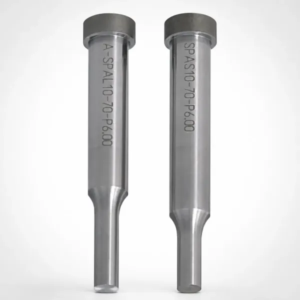
Treat these. Gate inserts and hot runner nozzle tips see the highest melt velocity at 20-60 m/s, so nitride or duplex them. Slides, lifters and cams carry sliding contact under pressure, which makes them prime DLC or CrN candidates. Core pins in glass-filled resins abrade at the shut-off, and core pins under 6 mm diameter take a 0.05-0.10 mm nitrided case. Cavity inserts in filled engineering resins such as PPS or PA66-GF30 benefit from a 0.15-0.25 mm nitrided case. Stripper plates, wear plates and guide post surfaces respond well to nitriding or nitrocarburizing at low cost. Replacement inserts built to drawing are easier to send out again later, so specify the treatment on custom mold inserts rather than on finished assemblies.
Leave bare. Mirror-finish cosmetic faces at SPI A1 to A2 should stay uncoated, because a 1-3 µm film changes gloss and can add a faint haze. Shut-offs held to 0.01 mm or tighter should not receive a 2-5 µm film unless the print is corrected for it. Fine textures such as VDI 27 or SPI C1 to D3 lose sharpness under a compound layer. Ejector pin bores and leader pin bores hold H7 fits, and nitriding can grow the pin 10-30 µm on diameter. Any area that will be welded in a future repair must be masked. Threads, dowel holes and ejector plate pockets should all be masked or left outside the treatment.
Masking is a drawing call-out. Send the coating or heat treat house a marked drawing. It must show treated and non-treated zones plus the masking method: copper plating, paint stop-off or fixturing. Unspecified masking is the most common cause of a returned tool that no longer assembles. For ±0.002 mm component geometry, a 3 µm unintended film is a 150% error against the tolerance.
Do the sequence math before quoting. Nitriding in the middle of a build adds 3-10 working days and requires a pre-grind allowance of 10-20 µm. PVD at the end adds 3-7 days and forces the part through final polish first. DieStrike quotes 2-5 weeks for injection molds. Treatment must be scheduled as a build step inside that window, not added as an afterthought at T1. Related planning detail sits in the heat treatment specification guide.
Coatings vs Texture and SPI Finishes
Cosmetic surfaces and hard surfaces pull in opposite directions. A coating reproduces whatever is under it, while nitriding changes the surface and usually dulls a polished or textured finish.
PVD is dimensionally honest but visually different. A 2-3 µm TiCN film on a polished insert keeps the geometry and the Ra value, yet the appearance shifts. TiCN reads grey-brown, TiAlN reads violet-grey, and CrN reads silver-grey. Gloss measured at 60° commonly drops 10-20% against an uncoated SPI A1 mirror. On a black or high-gloss housing part, that shift can change the visual match with the previous tool.
Nitriding changes the finish and needs a re-polish. A 5-15 µm compound layer forms with its own micro-roughness. An SPI A1 face can fall to roughly A2 or A3 appearance unless it is polished after treatment. Polishing back to A1 means removing 5-10 µm, which is most of the white layer, so the corrosion benefit disappears. The practical answer is to nitride the wear zones and mask the cosmetic zones, or accept a one-step finish change and re-approve the sample. The polishing sequence and Ra targets sit in the polishing guide.
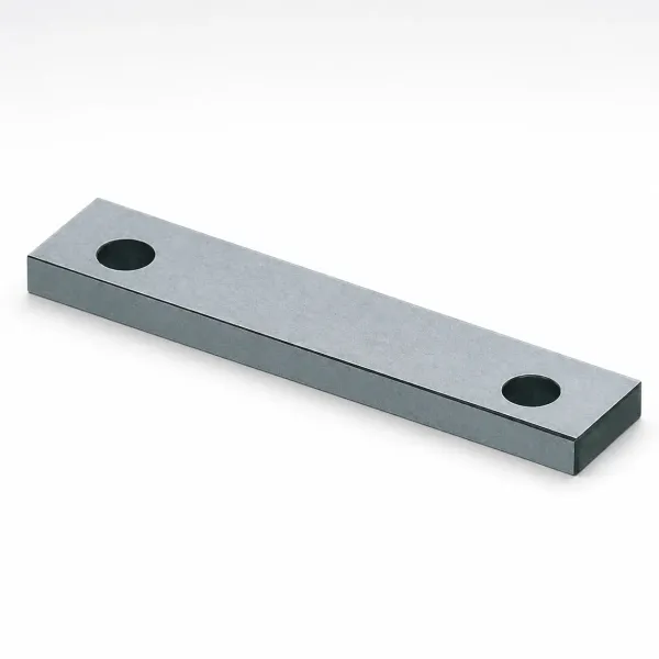
Texture depth interacts with film thickness. A grain etched to 20-30 µm depth tolerates a 2-5 µm film, because the film follows the texture instead of filling it. A fine matte finish at 3-5 µm Ra depth does not. In that case the coating levels the peaks slightly and the part reads glossier in the same moulding conditions. Add a texture step of 0.5-1.0 µm Ra to the specification if the finish must stay identical.
Test on a coupon first. When a part is both cosmetic and high wear, run a coated coupon through 500-1,000 shots. Compare gloss, colour and texture against the approved master sample. That test costs a few hundred dollars and one shift. Discovering the shift after 40,000 production shots costs a re-polish, a re-coat and a customer deviation.
Cost and Lead Time Impact
Surface treatment is a small line item against the insert it protects, yet it carries real schedule risk. Budget the cost band and the calendar days together.
Typical figures. Gas nitriding runs 3-7 working days and is the cheapest per part, often 20-60 USD for a batch of small components. Ion nitriding runs 5-10 days at a higher hourly rate, offset by shorter cycles. PVD runs 3-7 days at 40-150 USD per part depending on size and chamber load. DLC runs 5-10 days at a premium over CrN. Duplex treatment runs 6-12 days across two vendors and lands around 1.5-2.5x the cost of nitriding alone.
Calendar risk beats price risk. Most coating houses batch parts once or twice a week. A part delivered on Thursday may wait until Monday or Tuesday before the chamber runs. That wait, not the process time, is what pushes a T1 date. Build 5-10 days of float into the schedule for any tool with coated components, and confirm the coating house's batch day before releasing the insert.
Rework costs more than the treatment. If a PVD film spalls in the first 5,000 shots, the fix is strip, re-polish, re-coat, plus a shutdown. That is 3-5 days and 2-3x the original coating cost. Bad masking, EDM recast left in place or a wrong substrate hardness causes most of those returns. Inspection before the part leaves the shop prevents them.
Think in cost per 100,000 shots. A 200 USD treatment on a 1,200 USD gate insert that lasts 3x longer pays back in the first run. It also removes one unplanned stoppage. Compare that with a machine burden rate of 40-80 USD per hour. A single 8-hour shutdown wipes out the treatment budget for the whole tool. When a worn tool needs rebuilding, treat the repair as a chance to upgrade the surface specification. Restoring a known weak point only repeats the failure.
Acceptance Testing and Verification
A treatment is only as good as the paperwork behind it. Ask for measurements, not a process certificate. Five checks cover almost every nitriding and coating job.
Case depth and microhardness. Cut a witness coupon or a scrap part, polish a cross-section, and measure with a Vickers indenter at 0.3-0.5 kg load. Report case depth per ISO 18203 against a stated hardness criterion, usually core hardness plus 50 HV. A 0.15-0.25 mm target should report values inside 0.13-0.27 mm across the section.
Compound layer thickness. Measure the white layer on the same cross-section at 500-1,000x. Report the actual range, since 5-15 µm is a broad band. If the print says 0-3 µm for an impact edge, a 12 µm result is a reject, not a minor deviation.
Coating thickness and adhesion. Verify PVD thickness by XRF or a calotest crater on a witness coupon, expecting 2-5 µm within ±20%. Test adhesion with the Rockwell C indentation method per VDI 3198 and accept HF1 to HF2. HF4 or visible spalling around the indent means the part gets stripped and re-coated.
Corrosion performance. For PVC, chloride or flame-retardant service, request ASTM B117 salt spray results on a coupon. CrN typically reaches 96-500 h to first red rust depending on thickness and substrate. Nitrided coupons with the compound layer intact usually reach 100-200 h without red rust.
Dimensional and visual verification. Measure the treated part against the print with a CMM and record the change against the pre-treatment dimension. Store the result, the process parameters and the supplier lot number in the mold maintenance record so the next tool follows a proven recipe. DieStrike builds and qualifies tooling to ±0.005 mm mold accuracy and ±0.002 mm component geometry. Any treatment that moves a dimension outside that band is a documented deviation.
FAQ
Q1. Does nitriding make mold steel harder than PVD coatings?
No. Nitriding reaches 900-1,200 HV in the diffusion zone, while TiCN and TiAlN reach 2,800-3,300 HV. The difference is depth. Nitriding hardens 0.05-0.35 mm of steel, while PVD hardens only 2-5 µm of surface. For abrasive load over a long contact path, case depth usually matters more than peak hardness.
Q2. Can I nitride a mold after final polishing?
Not if the cosmetic finish matters. A 5-15 µm compound layer dulls a polished or textured surface, so nitride before the final polishing step and mask cosmetic zones. If the part must be polished after nitriding, expect to remove 5-10 µm, which takes most of the white layer with it.
Q3. How much growth should I plan for nitriding?
Plan 5-15 µm per side, or 10-30 µm on diameter, and pre-grind 10-20 µm undersize. Parts with fits tighter than 0.02 mm should be nitrided before final grinding. Always confirm on a witness piece from the same steel and heat lot before committing a production core pin.
Q4. Which treatment works best on PVC and flame-retardant resins?
CrN at 3-5 µm is the most reliable barrier, with salt spray results commonly in the 96-500 h band. Nitriding also works if you keep a 5-10 µm compound layer intact. That layer is brittle under impact, so use it on low-impact cores and gates, not on edges that take shock.
Q5. Is duplex nitriding plus PVD worth the extra cost?
On gate inserts, hot runner nozzles and high-wear slides in filled resins, yes. Duplex commonly delivers 2-4x the life of PVD alone and 5-10x bare steel, at 1.5-2.5x the cost of nitriding and 6-12 extra working days. On cosmetic faces and light-contact surfaces, the added thickness and cost bring no benefit.
The Bottom Line
Pick the treatment by failure mode and by where the geometry lets a process work. Nitriding covers abrasive load and depth. PVD gives thin, hard barriers on HRC 54-60 inserts. DLC handles adhesive pickup, and duplex covers both when one process is not enough. Pre-plan 5-15 µm of growth, mask cosmetic and precision zones, and verify case depth, adhesion and thickness with real measurements before the tool runs.
DieStrike builds IATF 16949 precision molds to ±0.005 mm with DFM feedback in 24 hours, and specifies surface treatment on the drawing from day one. Send the failure photos and the resin data sheet through our contact page. We will match the treatment to the wear mode before the insert is machined.
KEEP READING
Related Reading
How to Specify Heat Treatment for Mold Steel
Hardening, tempering and stress relief specs: HRC targets, soak times and what to write on the purchase order.
Read articleArticleDLC Coating for Mold Components: When It Pays Off
How DLC cuts friction on core pins, slides and ejector pins, and where the temperature limit rules it out.
Read articleArticlePre-Hardened vs Through-Hardened Mold Steel: How to Choose
HRC 30 pre-hardened blocks versus hardened and nitrided inserts, with the cost and repair trade-offs.
Read articleServiceMold Repair and Maintenance
IATF 16949 tool room support: welded repairs, re-polishing, re-nitriding and shutdown rebuilds.
Read articleNEXT STEP
Ready to Start Your Mold?
Send us your element dimensions or part numbers — our team responds within 24 hours with pricing and lead time.

Written by
Ray ChanMold Buyer's Guide Author · Precision Mold Manufacturing Specialist. Ray helps global importers, distributors and OEMs source factory-direct molds and mold parts.