
Holding Gear Tooth Profile Across an 8-Cavity Mold
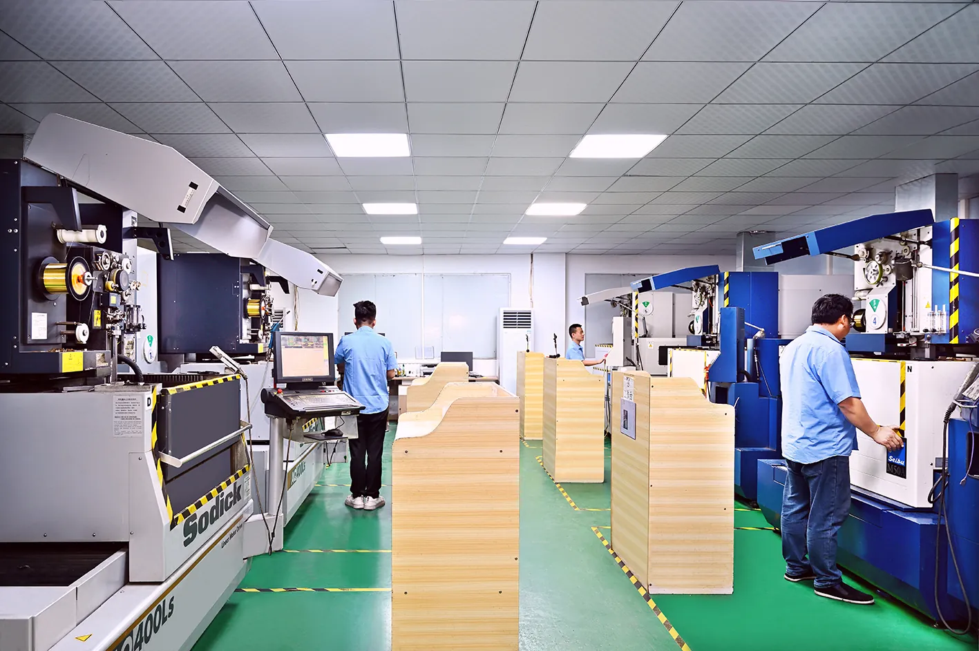
Table of Contents
Introduction
A home appliance OEM running a small drive gear program in POM (acetal) came to us with a tool they no longer trusted. The 8-cavity gear mold had been supplied by a previous toolmaker, and while it still produced parts, the parts were not the same part from cavity to cavity. Tooth profile deviation measured up to 0.06 mm between cavities — three times the 0.02 mm the gear train allowed — and the assembly line had started rejecting finished units on gear noise.
The gear itself is modest: a module 0.8, 24-tooth spur gear roughly 19 mm in pitch diameter, molded at an annual volume of 2 million pieces. Modest geometry, unforgiving tolerance. Because the noise appeared only after final assembly, the OEM was scrapping complete appliances — not gears, not sub-assemblies, whole units — and the cost of each reject kept climbing as value was added downstream.
They came to DieStrike for a rebuilt 8-cavity tool that could hold profile deviation inside ±0.02 mm across every cavity, verified by CMM before the tool left the shop.
The Snapshot
Here is the project at a glance — the part, the material, the tool, and the numbers that mattered.
| Part / Component | Module 0.8, 24-tooth spur gear |
| Resin / Material | POM (acetal) / S136 ESR cavity steel |
| Mold / Die Type | 8-cavity injection mold |
| Cavity Count | 8 |
| Annual Volume | 2 million parts/year |
| Critical Tolerance | ±0.02 mm tooth profile |
| Initial Problem | 0.06 mm cavity-to-cavity drift + gear noise |
| Result Summary | ±0.02 mm across all cavities, zero rejects |
- Module 0.8, 24-tooth spur gear in POM, molded at 2 million parts per year.
- Tooth profile drifted 0.06 mm cavity-to-cavity — three times the 0.02 mm the gear train allowed.
- Gear noise surfaced only after final assembly, so the OEM was scrapping complete appliances.
- The rebuilt tool holds ±0.02 mm across all eight cavities, with the CMM report shipped alongside the tool.
The Challenge
Gear molds fail quietly. The tool still filled, still ejected, still looked productive — but the geometry was drifting in ways that only showed up in a finished product. Three problems stacked up on this program.
First, tooth profile deviation ran up to 0.06 mm between cavities. In a gear train designed around 0.02 mm, that spread is not a quality nuisance; it is a functional failure. Gears from different cavities were effectively different parts, and interchangeability — the whole point of running eight cavities — was gone.
Second, the failure mode was expensive. Gear noise appeared only after the gear was assembled into the final drive unit, so the reject point sat at the end of the line. Instead of scrapping a 5-gram gear, the OEM was scrapping complete appliances. Every reject carried the cost of every assembly step that came before it.
Third, the tool was degrading as it ran. Dimensional drift appeared after roughly 20,000 shots as the previous tool's cavity steel wore at the tooth tips — a wear pattern that only gets worse, and a signal that the steel grade and the tooth-form machining were both wrong for a long POM program.
How We Solved It
The rebuild attacked all three failure points at once — accuracy in the steel, shrinkage that was measured instead of guessed, and a cavity material that would hold its geometry past the OEM's volume plan.
Steel and tooth-form accuracy. The tool was rebuilt in S136 ESR cavity steel hardened to HRC 48-52 — corrosion- and wear-resistant for long POM runs without profile drift. Gear tooth forms were wire-EDM'd into the hardened inserts at ±0.002 mm, and the gear bore was jig-ground for true position against the tooth form. Cutting the tooth geometry after hardening, rather than milling soft steel and heat-treating afterward, is what keeps a ±0.02 mm part profile actually achievable in production.
A measured shrinkage correction loop. POM shrinks roughly 1.8-2.2%, and a gear's tooth profile is the worst place to guess that number. We ran the correction as a trial-shot loop: first articles measured on the CMM at 24 hours, cavity scaling adjusted per the measured shrink, then a second trial to lock the geometry. This is the same discipline we apply inside our DFM and mold design review — the correction plan is defined before steel is cut, then verified against real parts, not assumed from a data sheet.
Verification on every cavity. Full gear inspection — profile, lead, and runout — was performed on every cavity before delivery, and the CMM report shipped with the tool. The same report is what the OEM's quality team uses for incoming acceptance, so there is no gap between what we measured in our shop and what they verify at their door. Precision work of this kind is a core capability across our mold-making operation.
The Results
| Tooth profile deviation | 0.06 mm → within ±0.02 mm across all 8 cavities |
| Cavity-to-cavity spread | Cut from 0.06 mm to 0.02 mm — gears interchangeable between cavities |
| Assembly noise rejects | Eliminated — zero gear-noise failures in the first production quarter |
| Dimensional stability | No profile drift after 200,000+ shots; CMM checks every 50,000 shots confirm stable geometry |
The numbers that matter to the OEM's bottom line: gears are now interchangeable between cavities, which restores the throughput the cavity count was bought for, and the noise reject line at final assembly is empty. The cost of the rebuild was paid back in the first quarter of scrapped-appliance savings alone.
Equally important is the stability story. After 200,000+ shots the tool still holds its geometry, with CMM checks every 50,000 shots confirming no profile drift — the tooth tips that wore out the previous tool at 20,000 shots are still holding on this one.
Why It Held
Gear molds fail on three things: tooth-form accuracy in the steel, shrinkage compensation that is guessed instead of measured, and cavity wear that shows up as drift. This tool attacked all three — wire-EDM'd forms at ±0.002 mm in hardened S136 ESR, a two-loop trial correction that locked the real POM shrinkage into the cavity scaling, and a cavity steel chosen to hold its geometry past 200,000 shots.
The gear inspection report that ships with the tool is the same one the OEM's quality team uses for incoming acceptance. When the customer's acceptance criteria and the toolmaker's verification standard are the same document, there is nothing left to argue about at trial — and nothing to rediscover at the 50,000-shot checkpoint.
KEEP READING
Related Reading
Extending Ejector Pin Life on a High-Cycle Connector Mold
A high-cycle connector mold was burning through standard ejector pins every 150,000 shots — steel grade and coating changes that ended the wear-driven stops.
Read case studyCase StudySTAVAX ESR Cores for Corrosion-Free Syringe Barrel Molding
POM off-gassing corroding SKH51 cores on a medical mold — mirror-polished STAVAX ESR cores ended the corrosion and the cleanroom shutdowns.
Read case studyArticleWire EDM for Mold Making: Accuracy, Surface, and Cost
Real numbers behind wire EDM: ±0.002 mm accuracy grades, Ra 0.2-0.8 µm finishes, white layer control, and cost drivers for your RFQ.
Read articleArticleHow to Hold ±0.002 mm: Precision Mold Tolerances
Tolerance classes, GD&T call-outs, steel stability, jig grinding, and the verification chain that keeps a 2-micron tolerance real in production.
Read articleNEXT STEP
Ready to Start Your Mold?
Send us your element dimensions or part numbers — our team responds within 24 hours with pricing and lead time.

Written by
Ray ChanMold Buyer's Guide Author · Precision Mold Manufacturing Specialist. Ray helps global importers, distributors and OEMs source factory-direct molds and mold parts.