
POM (Delrin) Injection Molding: Complete Guide
Table of Contents
A POM mold that fails on the first trial usually fails in the cavity math, not the resin. Compensate a gear cavity for 1.5% shrinkage on a material that shrinks 2.2%, and the molded pitch diameter comes out undersized — a steel change order that costs weeks. Cut a 5 mm boss without rethinking the gate, and the part leaves the press looking fine while a void hides in the center, ready to crack under load at 20,000 cycles. Both failures are visible on the drawing long before the steel is cut — and both are the reason this guide reads POM from the mold side, not the chemistry side.
POM — polyoxymethylene, also called acetal — is the engineering thermoplastic behind precision gears, bearing cages, snap-fit clips, pump impellers, and automotive fuel-system components. It is a highly crystalline material: roughly 60-80% of the volume locks into ordered crystallites as it cools (typical published crystallinity for molding grades). That crystallization buys the stiffness, fatigue resistance, and self-lubricating low friction that make POM the default for moving parts — and it is the source of the two numbers that decide whether a POM mold succeeds: a mold shrinkage of 1.8-2.2% that climbs past 2.5% in thick walls, and a post-mold shrinkage that keeps moving for days. Delrin is the DuPont brand name for acetal homopolymer; the trade uses the term loosely, and this guide treats POM and acetal as the working terms.
This guide is written for the people who buy and build the tool: mold buyers, tooling engineers, and manufacturing engineers. It walks from the properties that dictate mold decisions, through design rules specific to POM tooling — cavity compensation, void prevention, venting, and steel — into the processing window the mold must survive, and ends with defects traced to their mold-side root causes. Processing numbers follow typical published values for injection-molding grades; test methods are cited where they matter. DieStrike builds POM-capable tooling under IATF 16949 / ISO 9001 systems, with CMM-verified dimensions on every mold.
The Snapshot
- POM (polyoxymethylene / acetal) is a highly crystalline engineering thermoplastic; Delrin is a commercial homopolymer brand within the family.
- Mold shrinkage runs 1.8-2.2% typical and climbs past 2.5% in walls above ~4 mm — cavity compensation must be split by wall zone and carry a post-shrinkage allowance.
- Melting point ~165-175°C; process at a melt of 180-220°C into a mold at 60-100°C — mold temperature is the crystallization control.
- Density ~1.41 g/cm³ and water absorption 0.2-0.25% (typical published values) — far below nylon, which is why POM parts hold dimensions in humid service.
- Tensile strength 60-70 MPa and flexural modulus 2.6-3.1 GPa give gear teeth and snap fits their stiffness; the datasheet, not intuition, sets the fatigue limit.
- Walls above ~4 mm produce internal voids (center shrinkage) unless the gate packs the section before freeze-off — core out thick bosses instead of thickening them.
- Formaldehyde outgassing attacks tool steel: vent at 0.02-0.04 mm and specify S136-class stainless or coated inserts on long-run POM tools.
What Is POM Plastic?
POM plastic is a semicrystalline engineering thermoplastic built from repeating -CH₂-O- units — hence polyoxymethylene, the chemical name, and acetal, the family name used in the acetal molding trade. Commercialized in the 1950s-60s, it became the default for parts that slide, rotate, latch, or pump: gears, bushings, clips, impellers, and fuel-system components. The chemistry splits into two families that matter to tool buyers. Homopolymer (POM-H) carries the higher tensile strength and stiffness, with slightly higher shrinkage; copolymer (POM-C) resists hot water and alkaline attack better and releases less formaldehyde during processing. Delrin is the DuPont brand of homopolymer — when a buyer says "Delrin material," they usually mean acetal homopolymer properties. The family choice moves the shrinkage number the cavity is cut to and the venting and steel strategy, so lock it during DFM, not at the trial.
The property that rules POM tooling is crystallinity. Unlike amorphous materials such as ABS or polycarbonate, POM has a sharp melting point around 165-175°C (typical published values for molding grades), and when it cools inside the mold, 60-80% of the volume crystallizes. Crystallization releases heat, so the cooling layout must pull more energy per shot than an amorphous resin would. It drives shrinkage up to 1.8-2.2%, it makes shrinkage anisotropic — different in the flow direction than across it — and it continues after ejection: POM parts keep shrinking a little for days, so critical dimensions are judged at a fixed time after molding, often after annealing at 80-120°C.
Datasheet values come from standard methods — ASTM D955 shrinkage, D638 tensile, D790 flexural, D792 density, D570 water absorption; ISO 294-4, ISO 527, and ISO 178 are the equivalents. Compare grades using the same standard; numbers from different methods are not interchangeable.
POM Properties That Drive Mold Design
POM material selection and tool design are one decision, not two. The table below maps the POM properties that matter most to the specific mold decisions they drive. If a datasheet number is missing at RFQ time, this is the list to ask for.
| POM property | Typical value | What it drives in the mold |
|---|---|---|
| Mold shrinkage | 1.8-2.2% (2.5%+ in walls over ~4 mm) | Zone-by-zone cavity compensation; post-shrinkage allowance; gear pitch-diameter compensation |
| Melting point / crystallinity | ~165-175°C; ~60-80% crystalline | Mold temperature 60-100°C controls crystallization rate; cooling layout sets cycle and warpage |
| Melt flow | High; MFR often 5-40+ g/10 min, grade-dependent | Long flow lengths fill easily; thin-wall gears fill without high pressure, but packing is the critical phase |
| Water absorption | 0.2-0.25% at saturation | Drying before molding, but dimensionally stable in humid service — no conditioning needed like nylon |
| Tensile strength | 60-70 MPa | Gear tooth and snap-fit loading; draft and ejection force estimates |
| Flexural modulus | 2.6-3.1 GPa | Wall thickness and rib decisions for stiffness; spring rate of snap fits |
| Coefficient of friction | ~0.2-0.35 vs steel, unlubricated | Polished cavity surfaces for sliding and gear parts; low ejection friction relaxes draft requirements |
| Degradation products | Formaldehyde above ~220°C; acetaldehyde when wet | Steel selection (S136-class, coatings); venting at 0.02-0.04 mm; corrosion allowance on long-run tools |
← swipe to scroll →
Values are typical published ranges for injection-molding grades; actual numbers vary by grade, fill level, and test method.
Shrinkage and post-shrinkage. POM is one of the higher-shrink engineering thermoplastics: 1.8-2.2% mold shrinkage for typical walls, above 2.5% in sections over about 4 mm. Shrinkage is crystallization-driven, so it is anisotropic — flow-direction and cross-flow values differ, typically by a few tenths of a percent — and it continues after ejection as crystallization completes. For gear molds this is the most consequential row in the table: the cavity tooth form is compensated at the expected shrinkage, and the measurement plan must account for post-shrinkage, or the gear pitch diameter drifts out of tolerance before PPAP.
Stiffness and fatigue. A flexural modulus of 2.6-3.1 GPa and tensile strength of 60-70 MPa (typical published values) are why POM snap fits spring, gear teeth hold load, and pump impellers keep their shape. POM also carries strong fatigue resistance — published endurance limits for unfilled grades commonly sit in the 25-35 MPa range at 10⁷ cycles — the property behind living hinges and long-life gears. For the mold, stiffness drives wall thickness and the clean ejection of thin, loaded tooth geometry.
Friction and wear. Unlubricated POM against steel runs at a coefficient of friction of 0.2-0.35 (typical published) — low enough that gears and sliders run dry. That is why cavity finish matters: a polished, low-roughness surface (Ra 0.2-0.4 µm on sliding faces is typical practice) keeps friction and wear predictable over millions of cycles; a rough EDM texture would polish itself in service.
Moisture and chemical behavior. Water absorption of 0.2-0.25% is an order of magnitude below nylon, which is why POM dimensions stay stable in humid air while nylon parts swell. The resin resists most solvents, fuels, and dilute alkalies — copolymer grades notably better against hot water and alkaline cleaners. Strong acids and oxidizers attack it, and its degradation products — formaldehyde, plus acetaldehyde when the resin was wet — attack unprotected tool steel. Those two facts decide the venting and steel strategy below.
Mold Design Considerations for POM
POM is high-flow and forgiving at the machine, but the tool carries the decisions that decide voids, flash, corrosion, and gear accuracy. The rules below are the ones that matter when the steel is being cut for a POM part.
Shrinkage compensation and post-shrinkage. Compensate cavities for 1.8-2.2% shrinkage, split by wall zone — thick sections shrink more than thin ones, and POM's crystalline anisotropy means flow and cross-flow directions differ. Gear cavities are compensated at the expected pitch-diameter shrinkage, then verified on the first trial with CMM data before the tool is signed off. Because post-shrinkage continues for days, add an allowance or an annealing step at 80-120°C (typical published practice) for parts with critical dimensions, and measure at a fixed time after molding. The zone-by-zone method is covered in our five shrinkage compensation rules.
Wall thickness and center voids. The defining POM defect is not a surface sink — it is the internal void. Above roughly 4 mm of wall, the outer skin freezes first, the still-molten core crystallizes and shrinks, and with no molten material left to feed it, a void opens in the center. Mold-side prevention: hold nominal walls in the 1.5-4 mm range, core out bosses and gear hubs instead of letting them run solid, and where a thick section is unavoidable, gate directly into it so packing feeds it until freeze-off. Multi-point gating and a higher mold temperature (slower freeze, longer packing window) are the second line of defense. A void that forms at the root of a gear tooth is a fatigue crack waiting for a load cycle.
Gate design. POM's high flow means gates are sized for packing, not filling. Edge, submarine, fan, and pin-point gates all work; a land length near 1 mm and gate depth at 50-80% of wall thickness are typical starting points, tuned at trial. The gate must stay molten longer than the thickest section takes to pack — if it freezes early, the center of the part voids. For gears, a single gate at the hub center gives symmetric flow and keeps weld lines out of the tooth roots; multi-gated gears carry weld lines, and those lines must land in non-loaded zones with a vent at the meeting point. Add a cold slug well on the runner so the first, cooled material does not reach the cavity.
Venting. POM outgasses: the resin releases formaldehyde when degraded and acetaldehyde when wet, and trapped air is compressed at the end of fill. Vents run shallower than for ABS — 0.02-0.04 mm depth is the typical guideline, because POM's high flow flashes at deeper vents. Every cavity needs a real venting path at the end of fill; deep blind pockets — common under gear hubs — may need vacuum venting.
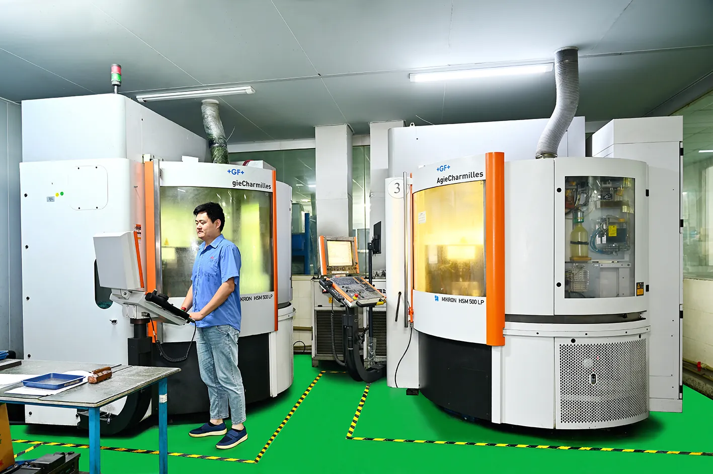
Mold steel and corrosion. Formaldehyde is corrosive to tool steel, and long-run POM tools that run hot show it as pitting near gates and vents. Standard P20 or 718-class prehardened steel (28-36 HRC) handles low-volume POM; production tools move to hardened steel — H13-class at 44-52 HRC is typical for cores — and high-cavitation, hot-runner, or long-life tools specify S136-class stainless or coated inserts (CrN or TiN PVD coatings are typical). The steel trade-offs are covered in our P20 vs H13 vs S136 comparison. For gear tools, tooth cavities are best built as hardened inserts: wire-EDM the tooth form, polish the flanks, and replace inserts without rebuilding the cavity plate — see our custom mold inserts page.
Precision gear mold specifics. Gear tooling is where POM earns its reputation, and the mold does the heavy lifting. Tooth forms are wire-EDM cut and finished to Ra 0.2-0.4 µm on the flanks; runout, pitch, and tooth-profile geometry are CMM-verified before trial. Because shrinkage is anisotropic, gating and cooling must be symmetric around the gear axis — a single hub gate and a balanced cooling layout keep the gear round. Mold-temperature uniformity around the circumference matters more than the absolute number: a 5-10°C side-to-side spread shows up as ovality and tooth-profile error. A replaceable insert keeps the mold base generic, and dimensional corrections cost less than recutting a one-piece cavity plate.
Draft and ejection. POM's low friction eases ejection — pins mark less than with softer resins — but the rules still apply: minimum draft of 0.5-1° per side, 1-2° on textured walls, polish in the direction of ejection, and enough pin area under hubs and ribs.
Cooling. Mold temperature of 60-100°C is the crystallization control, and the cooling layout — conformal where geometry allows — must hold cavity and core within a few degrees of each other. Imbalance is the fastest route to warpage, oval gears, and cycle drift, so cooling is designed in the same DFM pass as the shrinkage compensation.

Injection Molding POM: The Processing Window
The window below is the standard starting point for injection-molding grades (typical published practice); your grade datasheet overrides it.
Drying: 80-90°C for 2-4 hours. POM absorbs less moisture than nylon but still reaches 0.2-0.25% at saturation; the processing target is under 0.1%. Wet resin produces acetaldehyde splay, surface cracks, and a drop in mechanicals. A hopper dryer at 80-90°C for 2-4 hours is standard practice, and dried resin should stay covered — POM can re-absorb meaningful moisture in hours, not days.
Melt temperature: 180-220°C. The practical window for most grades. Above roughly 220-230°C with long residence, the polymer chain starts unzipping — the reaction that releases formaldehyde — showing up as odor, yellowing, and corrosive gas that attacks the mold. Short residence at the top of the window is fine; long residence is not. A screw with an L/D of at least 20:1 and a compression ratio around 2.5-3.5 is the usual recommendation for semicrystalline resins.
Mold temperature: 60-100°C. This is the crystallization control. The low end shortens the cycle and cools the skin fast; the high end gives a glossier, denser, more dimensionally stable part at a longer cycle. Precision parts — gears, clips with snap-fit tolerances — run at the top end, 80-100°C typical, because uniform, complete crystallization is what holds the molded dimension. Cavity and core should sit within a few degrees of each other, a balance designed into the cooling layout, not discovered on the machine.
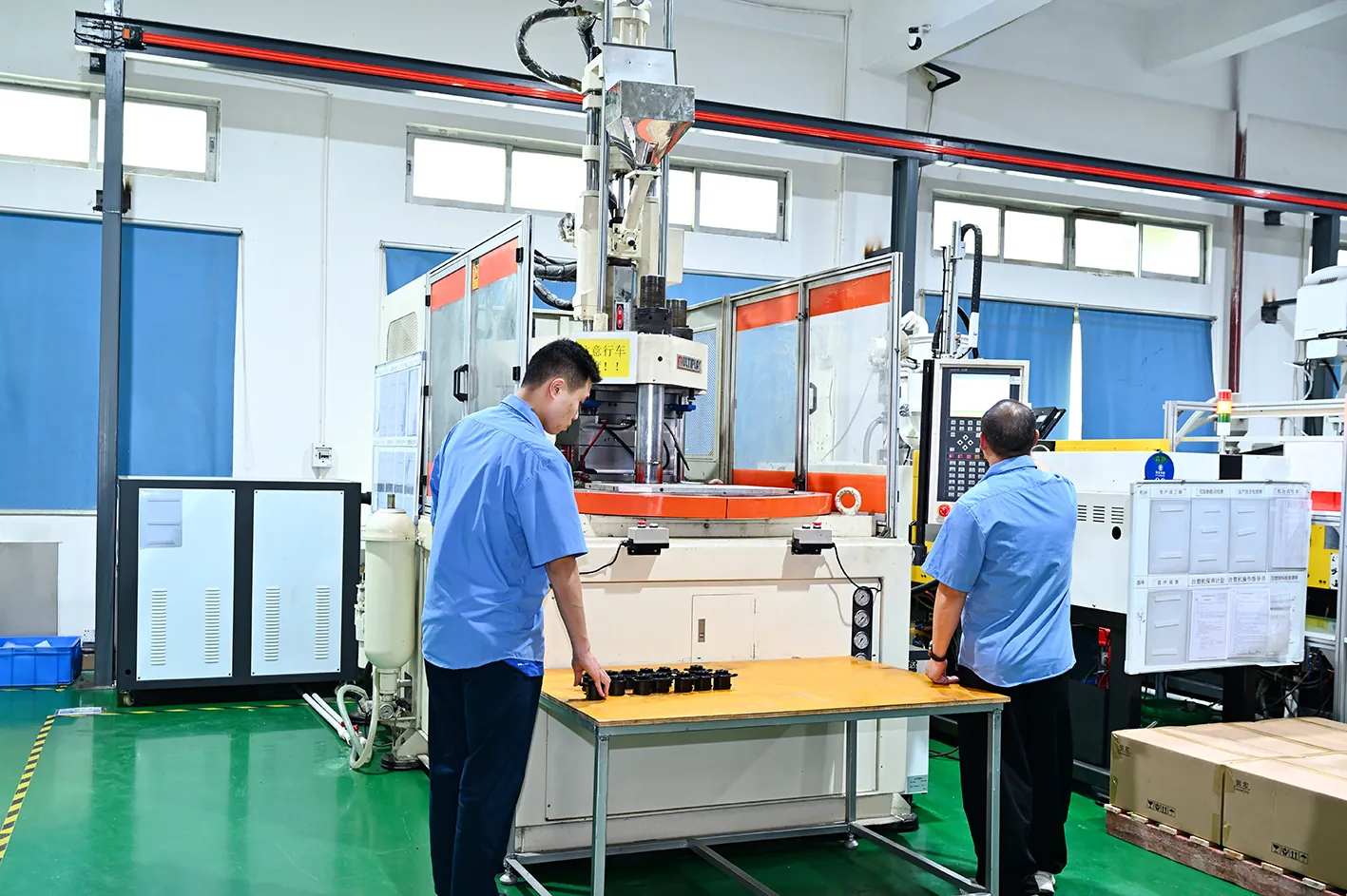
Pressures and speeds. Typical injection pressure runs 60-100 MPa (600-1,000 bar). Hold pressure is the critical number — 60-80% of injection pressure, held until the gate freezes, because packing is what stops voids. Back pressure stays low, 0.3-1.0 MPa, and screw speed moderate, to avoid shear heating that accelerates degradation.
Shrinkage: 1.8-2.2%. The number moves within its range with mold temperature and hold pressure — a hotter mold and harder packing push toward the low end. Compare parts at a fixed time after molding, and anneal at 80-120°C when the dimension is critical.
Venting. Vents of 0.02-0.04 mm depth are the typical guideline for POM — deeper vents flash on this high-flow material, shallower vents trap air and burn at the end of fill.
Common POM Applications
POM parts cluster where parts must move, latch, or pump without lubrication and without moisture sensitivity:
Precision gears and gear trains. Printer mechanisms, appliance timers, seat adjusters, and wiper systems run acetal gears that mesh with steel or POM without grease. These parts are molded in multi-cavity tools with hardened inserts and CMM-verified tooth geometry — the same discipline that drives our consumer electronics molding work.
Bearing cages, bushings, and sliding parts. With a coefficient of friction of 0.2-0.35 against steel (typical published), retainers and bushings run dry. Mold-side, the sliding surfaces get a polished cavity finish so friction and wear stay predictable over the part's life.
Snap-fit clips and fasteners. A flexural modulus of 2.6-3.1 GPa and strong fatigue resistance give clips their spring rate and their cycle life. Rib geometry, gate placement, and weld-line position decide whether the clip survives its first assembly — exactly the kind of call a DFM review catches on paper.
Pump impellers and housings. Copolymer grades handle water and mild chemicals, so impellers and pump bodies run in multi-cavity tools where balance — not just dimension — is the QC gate.
Automotive fuel systems. Fuel-sender components, fuel-pump parts, and seat-belt mechanisms use POM's fuel and solvent resistance. These tools run under automotive PPAP discipline with corrosion-resistant steel — fuel-grade service leaves no margin for formaldehyde pitting — under the same IATF 16949 system DieStrike applies to its automotive injection molding work.
Gear and fuel-system tooling alike is cut, hardened, and CMM-verified on DieStrike's mold making line before it reaches the press.

POM Defects: Mold-Side Root Causes and Fixes
Most POM rejects trace to a mold design decision, not a bad shot. The table below maps each defect to its mold-side root cause and the tooling fix. For the systematic workflow, see how to troubleshoot mold defects.
| Defect | Mold-side root cause | Tooling fix |
|---|---|---|
| Center voids (internal shrinkage) | Wall above ~4 mm; gate freezes before the core packs | Core out thick sections; gate into thick zones; multi-point gating; higher mold temperature keeps the gate molten through hold; high hold pressure and time |
| Sink marks | Ribs or bosses thicker than ~60% of wall; packing ends at freeze-off | Ribs at 50-60% of wall thickness; gate sized so packing reaches the thick zone; adequate hold pressure and time |
| Weld lines | Flow fronts meet at a tooth root, cosmetic zone, or loaded area; no vent at the weld | Single hub gate for gears; move gates so fronts meet at a vent or non-loaded zone; add venting at the meeting line; raise mold temperature |
| Splay / silver streaks | Wet resin (acetaldehyde) or degraded, overheated melt | Dry at 80-90°C for 2-4 hours; check the dryer mid-run; lower melt temperature or shorten residence |
| Warpage / dimensional drift | Non-uniform cooling; anisotropic shrinkage; post-mold crystallization | Balanced cooling and uniform mold temperature; symmetric gating; wall uniformity; annealing at 80-120°C |
| Flash | Vents too deep or parting-line wear on a high-flow material | Vents at 0.02-0.04 mm; hardened steel on parting lines; verify clamp force |
| Cavity corrosion / pitting | Formaldehyde attack on unprotected steel near gates and vents | S136-class stainless or coated inserts (CrN/TiN); scheduled mold maintenance; keep melt inside the window |
| Burn marks at end of fill | Trapped air compressed past the resin's degradation point | Real vents at 0.02-0.04 mm; vacuum venting on deep, blind pockets; slower second-stage fill |
← swipe to scroll →
Center voids deserve the deepest dive. The failure chain: the skin freezes, the core crystallizes and shrinks, and with the gate already frozen, no material can feed the gap — a void opens. Check by cross-sectioning, X-ray, or simply by tracking part weight against a known-good shot. The fix is architectural: walls at or under 4 mm, thick bosses cored out, gates sized and placed so the thick section packs before freeze-off, and mold temperature high enough to keep the gate molten through hold. A void in a gear tooth root is a fatigue crack waiting for a load cycle — treat it as a tooling issue, not a shot-to-shot issue.

Weld lines on gears. Two or more gates around a gear hub put weld lines straight through the tooth ring, and a weld line at a tooth root is the weak point under bending load. Gate at the hub center for symmetric flow; where geometry forces multiple gates, land the weld at a vent in a non-loaded zone and run the mold temperature at the top of the window.
Splay. Silver streaks radiating from the gate usually mean wet resin or an overheated melt — check the dryer and the residence time before touching the mold. Splay that returns mid-run points at the dryer, not at the tool.
POM vs Nylon vs PBT: Comparison Table
Two comparisons dominate POM selection: POM vs nylon, because both are the classic gear and bearing materials, and POM vs PBT, because both are semicrystalline engineering thermoplastics competing in electrical and automotive parts. Values are typical published ranges for injection-molding grades.
| Property | POM (acetal) | Nylon (PA66) | PBT |
|---|---|---|---|
| Density (g/cm³) | ~1.41 | 1.13-1.15 | 1.30-1.32 |
| Tensile strength (MPa) | 60-70 | 60-85 (dry as molded) | 50-60 |
| Flexural modulus (GPa) | 2.6-3.1 | ~2.8 | ~2.3-2.5 |
| Water absorption (24 h, %) | 0.2-0.25 | ~1.2-1.5 | ~0.08 |
| Mold shrinkage (%) | 1.8-2.2 | 1.5-2.0 | 1.5-2.0 |
| Melting point (°C) | ~165-175 | ~255-265 | ~225-230 |
| Moisture sensitivity in molding | Low-moderate | High — dry to under 0.2% | Low |
| Friction / wear | Low friction, self-lubricating | Higher friction; tough, abrasion-resistant | Higher friction |
| Dimensional stability in humidity | Good | Poor — absorbs moisture and swells | Excellent |
| Typical use | Gears, clips, impellers, fuel parts | Gears, bushings, clips, under-hood parts | Connectors, electrical housings |
← swipe to scroll →
Values are typical published ranges for injection-molding grades. PA66 water absorption at saturation is much higher than the 24-hour number — conditioning changes both its dimensions and its properties.
POM vs nylon. Nylon is the tougher sibling: higher tensile in dry-as-molded grades (60-85 MPa), better impact, and a melting point near 255-265°C that survives under-hood heat. Its cost is moisture: PA66 absorbs 1.2-1.5% in 24 hours and far more at saturation, so dimensions, stiffness, and friction move with humidity unless the part is conditioned and the design accounts for it. POM's 0.2-0.25% absorption keeps dimensions stable, its friction is lower, and it needs no moisture management in service. For precision gears in varying humidity, POM is the usual answer; for impact, abrasion, and sustained heat, nylon — see our nylon material guide for the full treatment. Both are semicrystalline, so both demand the same cavity compensation discipline.
POM vs PBT. PBT is the electrical connector material: the lowest moisture pickup of the three, good dielectric behavior, and solid chemical resistance. It is less stiff and less fatigue-resistant than POM, and its shrinkage sits in a similar range, so the tooling discipline transfers directly. When the part is a connector housing, PBT is usually the answer; when it moves, latches, or carries load, POM.
Frequently Asked Questions
Q1. What is POM plastic?
POM plastic — polyoxymethylene, also called acetal — is a highly crystalline engineering thermoplastic used for precision gears, bearing cages, snap-fit clips, pump impellers, and fuel-system components. Its defining traits are high stiffness (flexural modulus 2.6-3.1 GPa), low friction, strong fatigue resistance, and low moisture absorption (0.2-0.25%, typical published values).
Q2. Is Delrin the same as POM?
Delrin is the DuPont brand name for acetal homopolymer. POM is the generic family, which includes homopolymer and copolymer grades. When engineers say "Delrin material," they usually mean acetal homopolymer properties — and the mold is designed to the grade's datasheet, not the brand.
Q3. What is the POM shrinkage rate?
Mold shrinkage for POM runs 1.8-2.2% (typical published values), climbing above 2.5% in walls over about 4 mm. Because the material is crystalline, shrinkage is anisotropic and continues after ejection as crystallization completes — so cavities are compensated zone by zone, and critical dimensions are measured at a fixed time after molding, often after annealing at 80-120°C.
Q4. What is the POM melting point?
POM melts around 165-175°C (typical published values for molding grades). It is processed at a melt temperature of 180-220°C into a mold held at 60-100°C. Sustained melt temperatures above roughly 220-230°C degrade the resin and release formaldehyde, which corrodes tool steel.
Q5. Does POM absorb water?
Yes, but far less than nylon: 0.2-0.25% at saturation versus roughly 1.2-1.5% for PA66 in 24 hours. That low absorption is why POM parts hold their dimensions in humid service. The resin still needs drying at 80-90°C for 2-4 hours before molding to avoid splay.
Q6. Delrin vs nylon: which is better for gears?
For precision gears that must hold dimensions in varying humidity, POM is the usual answer: lower friction, stable dimensions, and strong fatigue resistance. Nylon wins where impact, abrasion, or sustained heat dominate — and the design must manage its moisture-driven dimensional change. Both are semicrystalline, so both need the same cavity compensation discipline.
The Bottom Line
POM is unforgiving on paper and reliable in the tool: compensate 1.8-2.2% shrinkage zone by zone, keep walls under 4 mm or core them out, vent at 0.02-0.04 mm, specify corrosion-resistant steel. Voids and outgassing trace to the mold, not resin. DieStrike delivers CMM-verified POM tooling with 24-hour DFM review.
KEEP READING
Related Reading
ABS Injection Molding: The Complete Material Guide
ABS injection molding for buyers and mold engineers: shrinkage 0.4-0.
Read articleArticleEjector Pin Steel: SKD61 vs H13 — What's the Difference?
SKD61 (JIS) and H13 (AISI) are two names for the same 5% chromium hot-work steel; ejector pins in both grades harden to…
Read articleArticleLiquid Silicone Rubber (LSR) Injection Molding Guide
Liquid silicone rubber (LSR) is a two-component platinum-cured thermoset with -50°C to +250°C service life.
Read articleArticleNylon (PA) Injection Molding: Grades, Properties & Processing
Nylon (PA) injection molding guide: PA6, PA66, PA12, PA46 and glass-filled grades compared — melting points, shrinkage…
Read articleNEXT STEP
Ready to Start Your Mold?
Send us your element dimensions or part numbers — our team responds within 24 hours with pricing and lead time.

Written by
Ray ChanMold Buyer's Guide Author · Precision Mold Manufacturing Specialist. Ray helps global importers, distributors and OEMs source factory-direct molds and mold parts.