
9 Mold Steel Selection Errors in Automotive Tooling
Table of Contents
The wrong mold steel does not fail on the first shot. It fails quietly at shot 60,000, when the gate on a glass-filled POM part rounds off and the fill rate drifts. It fails at shot 120,000, when pitting from PBT outgassing starts showing up on a class-A surface. It fails during polish, when inclusions in a standard-ingot H13 block open into pinholes on a mirror cavity. Every failure has a name: corrosion, gas attack, polish failure, wear, scrap.
Every one traces back to a steel decision made before the first chip was cut. Automotive tooling punishes guesswork harder than most work. Annual volumes of 100,000-500,000 parts are routine. Connector housings, sensor bodies, and interior trims run on 24/7 schedules. An unplanned shutdown costs more than the steel ever would.
A production mold built to DieStrike's IATF 16949 and ISO 9001 system holds ±0.005 mm standard and ±0.002 mm precision. At that level, steel is not a cost line. It is the first tolerance decision.
This article covers nine steel selection errors we see on automotive tools, with the numbers behind each one. For each error you get the mistake, the typical figures, the correct selection, and the resulting failure.
The Snapshot
- Pre-hardened P20 runs 28-32 HRC (typical). It wears out on abrasive resins well before 500k shots. H13 at 46-52 HRC is the standard fix for high-volume automotive tools.
- PBT and PA66 outgas corrosive species at melt. Uncoated H13 cavities can pit within 50k-150k shots (typical field reports). Stainless or coated steel is the correct answer.
- ESR-refined steel costs roughly 10-25% more than standard ingot (typical published premium). It removes most inclusions that cause mirror-polish pinholes.
- Stainless mold steel costs 1.5-2.5x H13 material (typical). H13 plus a PVD coating covers most corrosion cases at a fraction of the price.
- BeCu inserts carry 4-7x the thermal conductivity of tool steel (typical published range). They can cut cycle time 10-30% on cooling-heavy cores.
Error 1: Pre-Hardened P20 on High-Volume Tools
P20 (DIN 1.2311) is the default economy steel for prototype and low-volume work. It ships pre-hardened at 28-32 HRC (typical), machines fast, and polishes well. For a 10,000-shot tool it is the right call. For a 500,000-shot automotive connector or housing, it is a timer.
The Wear Numbers
Wear resistance tracks hardness. Published tool-steel data shows that moving from 30 HRC to 50 HRC roughly doubles to triples abrasive wear life in most mold-steel comparisons. On a glass-filled resin like PA66-GF30 or POM-GF25, a P20 gate can round off and change the fill pattern within 100k-300k shots (typical shop experience). Once the gate geometry drifts, the part follows: flash, short shots, and dimensional drift that shows up on the CMM report.

P20 also responds poorly to weld repair. When a worn P20 gate is welded and re-cut, the heat-affected zone softens and the repair fails again inside a short run. You do not repair a worn high-volume cavity , you re-cut it or replace the insert. Either way, the program stops.
The correct selection: spec H13 (DIN 1.2344) at 46-52 HRC for tools above roughly 500k shots. Use a D2-class grade where extreme abrasive wear is expected. DieStrike builds production molds in 2-5 weeks. We hold HRC 62 on wear surfaces where the failure mode demands it. The steel premium over P20 is small next to one unplanned mold-down.
Error 2: Ignoring Resin Outgassing Corrosion
Some automotive resins attack steel chemically, not mechanically. PBT and PA66 outgas at melt temperature , 260-290°C for PBT, 270-300°C for PA66 (typical published melt ranges). The breakdown products include acidic species that attack chromium-depleted zones in the steel. Flame-retardant grades add halogen compounds that make the attack worse.
The result is corrosion pitting on the cavity surface, often invisible until the part picks it up. On uncoated tool steel, field reports put visible pitting between 50k-150k shots on aggressive FR grades (typical). The pits show as surface defects on the molded part. Re-polishing only opens the pits deeper. Vents and shutoff edges corrode first, because that is where the gas concentrates, so flash appears at the same time as the surface defects.
The correct selection: use stainless grades like S136 (DIN 1.2083) at 48-52 HRC when the resin data sheet warns about outgassing. Or keep H13 and add CrN or TiAlN PVD at 2-4 µm thickness (typical). Stainless costs 1.5-2.5x H13 material (typical). The coating route often wins on cost for interior parts that do not need the full stainless package.
Error 3: Wrong Hardness Target for the Failure Mode
Hardness is a trade, not a target. Specifying maximum hardness everywhere ignores the two different ways molds die. Wear-dominated zones , gates, shutoffs, and slides , need maximum hardness. Impact and toughness-dominated zones , thin cores, sharp corners, and slides that take side loads , need enough toughness to survive without cracking.
Wear vs Toughness
At 60-62 HRC, a steel like D2 is nearly immune to abrasive wear but brittle enough to chip on a sharp core corner. At 46-52 HRC, H13 has the toughness to take impact but wears faster at a gate. The trade-off is steep. Impact toughness can drop by half or more between 50 HRC and 60 HRC in the same grade (typical supplier data).
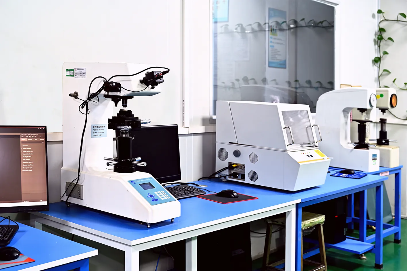
The correct selection: map the failure mode before you spec. Wear surfaces: 56-62 HRC, plus coating where galling is a risk. Toughness-critical cores: 46-52 HRC in H13 or a maraging grade. DieStrike specs HRC 62 on wear faces and a lower hardness on impact-loaded cores. Each insert gets a hardness check before cutting.
The failure is predictable. An over-hardened core chips in the first 10,000 shots. An under-hardened gate erodes by 100,000. Both stop the line. Both were preventable at the steel spec.
Error 4: Skipping ESR/VAR Refining for Cosmetic A-Surfaces
Standard-ingot tool steel carries inclusions , oxide particles, sulfides, and segregation left over from melting. Most of them are harmless below the surface. The problem is the ones that sit at the surface of a polished cavity. When you polish a mirror A-surface down to SPI A-1 (Ra 0.012 µm, typical spec), an inclusion at the surface opens into a pinhole. On a piano-black automotive trim, one pinhole is a reject.
ESR (electro-slag remelting) and VAR (vacuum arc remelting) refining remove most of those inclusions. Published data typically shows inclusion counts dropping by an order of magnitude or more compared with standard ingot. That is why every automotive A-surface spec we see for mirror finishes calls for ESR steel.
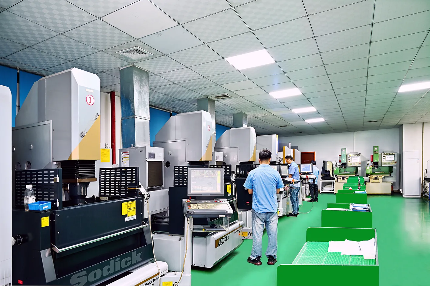
The polish result is measurable. An ESR cavity reaches SPI A-1 with predictable effort. A standard-ingot cavity of the same grade often stops at SPI B-1 or worse, because inclusions keep opening as you polish (typical shop experience).
The correct selection: for class-A cosmetic surfaces, spec ESR-refined H13 (1.2344 ESR) or S136 ESR. The typical premium over standard ingot is 10-25%. Skipping it to save on the block is the most expensive shortcut here. It fails at the very end of the build, during polish, after all the machining money is spent.
Error 5: Over-Specifying Stainless Where H13 Plus Coating Suffices
The mirror image of Error 2 is buying stainless for every tool "just in case." Stainless runs 1.5-2.5x the material cost of H13 (typical). It machines slower because it work-hardens. It also conducts heat less well , about 24 W/m·K for 420 stainless versus 28 W/m·K for H13 (typical published values). On a cooling-sensitive tool, you pay twice and get a hotter cavity.
The correct selection: match the steel to the proven chemistry problem, not the fear of one. Stainless or a coated surface is justified when the resin data sheet documents outgassing attack. It is also justified for high-heat parts near the exhaust or engine bay. For standard interior and connector work, H13 at 48-52 HRC plus a 2-4 µm CrN or TiAlN PVD coating (typical) works. It gives corrosion and wear protection at a fraction of the stainless cost.
The failure from over-specifying is not a broken mold , it is a wasted budget and longer lead times on every tool. Steel cost compounds across a 16-cavity automotive tool.
Error 6: Ignoring Thermal Conductivity on Cooling-Heavy Tools
Tool steel conducts heat poorly. H13 sits around 25-29 W/m·K (typical published value). Thick bosses and ribs cool slowly, and sink marks form. The fix is copper alloy inserts.
Beryllium copper (BeCu) runs roughly 105-130 W/m·K. High-conductivity grades reach 200+ W/m·K (typical published range). That is 4-7x the conductivity of steel.
That is 4-7x the conductivity of steel. Published case data on BeCu inserts typically shows 10-30% cycle-time reductions on cooling-heavy parts. The arithmetic is easy to check. Take a 45-second cycle and a 15% reduction , about 7 seconds saved per shot. Across 400,000 shots, that is roughly 770 hours of machine time (typical arithmetic).
The insert pays for itself before the tool is half worn. On a multi-cavity connector mold, the saving multiplies across every cavity. That is why BeCu is standard on cooling-heavy cores rather than a specialty option.
The correct selection: put BeCu inserts at local hot spots: bosses, ribs, and thick sections where water lines cannot reach. Keep BeCu out of high-stress shutoff zones. It is softer than tool steel, roughly 36-44 HRC (typical). It will not carry clamp load the way steel will.
Error 7: Mixing Steel Grades Without Matching Thermal Expansion
Every steel expands when the mold heats to its 60-120°C operating range. The coefficient of thermal expansion (CTE) differs by grade. P20 and H13 run about 11-13 µm/m·K. Stainless runs around 10-11 µm/m·K. BeCu sits near 17 µm/m·K.
Aluminum alloys approach 23 µm/m·K (typical published values). Now do the arithmetic on a 100 mm insert at an 80 K temperature rise. Steel grows roughly 0.10 mm; aluminum grows roughly 0.18 mm. If an aluminum core is trapped inside a steel cavity with no allowance, the 0.08 mm difference has to go somewhere.
It usually goes into a cracked insert or a flash line at the parting surface. Multi-material inserts are common in automotive molds: steel carriers with BeCu cooling cores, or stainless wear pads on H13 slides.
The correct selection: match CTE within about 2 µm/m·K for rigidly located inserts, or design a slip fit that absorbs the difference. Document the growth calculation on the drawing. The failure is a cracked insert or flash that appears only at running temperature. It is the hardest kind to diagnose, because the mold looks perfect cold.
Error 8: Skipping Stress Relief on Large Blocks
Large mold steel blocks , 300 mm and up , carry residual stress from the rolling and forging process. Rough machining removes material unevenly, which redistributes that stress. If the block goes straight from rough machining to hardening, the stress releases inside the heat-treat furnace. The cavity moves. Published shop data typically puts distortion at 0.05-0.2 mm on blocks that skip intermediate stress relief.
That is enough to push a ±0.005 mm tolerance mold out of spec before it ever runs. The distortion shows up on the CMM after hardening, when the insert is already too hard to machine easily.

The correct selection: on large blocks, rough machine to within a few millimeters of finish. Stress relieve. Then finish machine and harden. The extra heat-treat step adds days, not weeks. It is standard practice on every large automotive tool we build.
Error 9: Ignoring Asymmetric Wear Between Core and Cavity
The core and cavity halves of a mold do not wear equally. The core side slides against the melt during ejection. It carries the highest shear from the flowing resin. It typically runs hotter than the cavity side. On abrasive resins, cores can wear two to three times faster than the cavity (typical field observation).
Wear shows up first as dimension drift on the core features. Then it shows up as flash at the parting line.
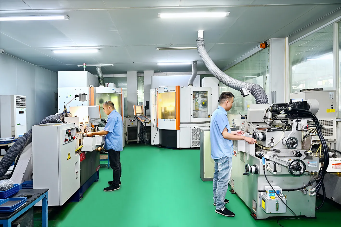
The correct selection: spec the core and cavity independently. On high-wear tools, run the core side 2-4 HRC harder than the cavity, or coat the core with CrN or TiAlN. It is normal for the two halves to use different grades. The mistake is assuming one spec fits both. The correct call on a 500k-shot tool is a hardened, coated core against a polishable, slightly softer cavity.
Steel Selection at a Glance
This table summarizes the grades that cover most automotive tooling work, with typical hardness and the correct use for each. Prices and hardness values are typical published ranges unless marked as DieStrike standard. Use the two tables together when you write the next RFQ.
| Grade | Typical Hardness | Best For | Avoid For |
|---|---|---|---|
| P20 (1.2311) | 28-32 HRC | Prototypes, low volume, quick turn | High-volume or abrasive resin tools |
| H13 (1.2344) | 46-52 HRC | Production cores and cavities | Corrosive resin attack without coating |
| ESR H13 (1.2344 ESR) | 48-52 HRC | Mirror-polish A-surfaces | Non-cosmetic, non-critical zones |
| S136 (1.2083) | 48-52 HRC | Corrosive resins, high-polish work | Cost-sensitive tools where coating suffices |
| D2 (1.2379) | 58-62 HRC | Extreme abrasive wear surfaces | Impact-loaded thin cores |
| BeCu (C17200) | 36-44 HRC | Cooling hot spots, inserts | High-load shutoff zones |
← swipe to scroll →
The nine errors, their symptoms, and the correct practice:
| Error | Symptom | Correct Practice |
|---|---|---|
| P20 on high-volume tools | Gate wear, flash by 100k-300k shots | H13 at 46-52 HRC for 500k+ shot tools |
| Ignoring outgassing corrosion | Pitting on cavity, part surface defects | S136 or H13 with CrN/TiAlN coating |
| Wrong hardness target | Chipped cores or eroded gates | Match HRC to the failure mode |
| Skipping ESR/VAR | Pinholes in mirror polish | ESR grades for A-surface cavities |
| Over-specifying stainless | Higher cost, slower cycles, no benefit | H13 plus PVD coating when chemistry allows |
| Ignoring thermal conductivity | Sink marks, long cycles, warpage | BeCu inserts at hot spots |
| Thermal expansion mismatch | Cracked inserts, flash at running temp | Match CTE or design slip fits |
| Skipping stress relief | 0.05-0.2 mm distortion after hardening | Rough, stress relieve, finish, harden |
| Asymmetric wear ignored | Core dimension drift, parting-line flash | Harder or coated core vs cavity |
← swipe to scroll →
Two more selection rules apply across every error above. First, put the hardness and the grade on the drawing. A verbal spec disappears by the time the block is ordered. Second, verify the delivered steel. A hardness check on every insert catches a substitution before it becomes a scrap rate.
FAQ
Q1. What hardness should automotive mold steel be? It depends on the failure mode. Wear surfaces run 56-62 HRC; toughness-critical cores run 46-52 HRC in H13. DieStrike's standard is HRC 62 on wear faces, verified per insert. Do not spec one number for the whole tool.
Q2. Is stainless steel always better for corrosion resistance? No. Stainless costs 1.5-2.5x H13 material (typical) and conducts heat worse. H13 with a 2-4 µm CrN or TiAlN PVD coating (typical) covers most outgassing-corrosion cases at lower cost. Reserve stainless for proven chemistry problems or high-polish requirements.
Q3. What is ESR steel and when do I need it? ESR (electro-slag remelting) refines the steel and removes most inclusions, at a typical 10-25% premium. You need it when the part demands a mirror A-surface polish , SPI A-1 or better , where a single inclusion becomes a reject pinhole.
Q4. How do I know if I need BeCu inserts? When a thick boss, rib, or core runs hotter than the rest of the cavity and causes sink marks or long cycle times. BeCu carries 4-7x the thermal conductivity of steel (typical). Keep it out of high-load shutoff zones.
Q5. Can I upgrade an existing P20 mold to handle more shots? Partially. You can add coatings or BeCu cooling inserts. You cannot fix a worn P20 gate with harder steel , you re-cut or replace the insert. If the program calls for 500k+ shots, the steel decision belongs at the RFQ stage, not mid-run.
Q6. What steel should I specify on an RFQ for a 500k-shot automotive tool? H13 at 46-52 HRC for cores and cavities, ESR H13 for any class-A surfaces. BeCu inserts at known hot spots. A coating decision based on the resin chemistry. Compare the full picture in our guide to P20 vs H13 vs S136.
The Bottom Line
Mold steel selection is a risk trade, not a shopping list. P20 saves money on low-volume tools and costs a program on high-volume ones. Stainless buys corrosion resistance and charges you 1.5-2.5x for it. ESR costs 10-25% more and is the only reliable way to hold a mirror A-surface.
Every grade has a job. Every error in this article is a grade doing the wrong job. Start the selection with three questions: what volume, what resin chemistry, and what surface finish. The answers put you on the right row of the table above. Then put the grade and hardness on the drawing.
Verify the delivered block, and let the tool run its full life. DieStrike builds precision automotive molds under IATF 16949 and ISO 9001. We run 120+ machines in one factory. Our customers include TE Connectivity, Amphenol, Luxshare, and Dongshan Precision.
Standard tolerance is ±0.005 mm; precision work holds ±0.002 mm. Production molds ship in 2-5 weeks, standard parts in 3-7 days. When the steel is right, the mold runs to its number , that is the whole discipline.
For medical-grade and corrosion-sensitive work, see our guide to selecting mold steel for medical molds. For automotive program planning, start from the automotive tooling overview.
NEXT STEP
Ready to Start Your Mold?
Send us your element dimensions or part numbers — our team responds within 24 hours with pricing and lead time.

Written by
Ray ChanMold Buyer's Guide Author · Precision Mold Manufacturing Specialist. Ray helps global importers, distributors and OEMs source factory-direct molds and mold parts.