
Die Lines vs Gate Blush: Causes and Mold-Side Fixes
Table of Contents
A connector OEM ran 30,000 glass-filled PA66 housings and scrapped 1,800 of them in one week. The rejects carried fine scratches along the sidewalls that a molder first blamed on "dirty resin." The real cause sat in the tool: 0.25 degree of draft on a textured core, polished against the pull direction. Meanwhile a PC lens program fought a different ghost, a whitish halo around the gate that shifted every time pack pressure moved 5 bar. Two defects, two owners, one confusion. Die lines are mechanical damage from ejection. Gate blush is stress whitening from fill and pack. Treat them as the same problem and you will re-polish a gate that needed resizing, or resize a gate while the core keeps scratching parts.
This guide separates the two failure modes from the mold side. It covers where each defect appears, the nine tooling root causes behind them, a visual identification table, and the mold-side fixes with typical specs: 0.5-1 degree of draft per side, Ra 0.2-0.4 um polish along the draw direction, gate shear limits and DLC coating for glass-filled service.
The Snapshot
- Die lines (drag marks): linear scratches on sidewalls, cores and slider faces, created when the part releases. Typical cure is 0.5-1.0 degree of draft per side plus polish lines running parallel to the draw direction.
- Gate blush (gate halo): localized haze or stress whitening within 2-10 mm of the gate. Typical cure is a larger gate, lower shear rate below 40,000-60,000 1/s for sensitive resins, and corrected gate aim.
- Polish target: Ra 0.2-0.4 um is typical for clean release on untextured cavity walls. SPI B-1 to A-3 range covers most gloss and release needs.
- Wear context: glass-filled resins abrade pre-hardened P20 (HRC 28-32) fast. Hardened cavities at HRC 50+ or DLC coatings at 1-3 um with friction coefficients near 0.1 are typical countermeasures.
- DieStrike baseline: cavities heat treated to HRC 62, mold tolerances held to ±0.005 mm and part geometry to ±0.002 mm, with DFM feedback in 24 hours.
What Are Die Lines and Drag Marks?
Die lines, also called drag marks or scuff marks, are scratches the part picks up while it leaves the mold. The surface damage happens at ejection, not during fill. As the cavity opens and ejector pins push, the part slides against the core, the cavity wall, the sliders and the parting line edges. Any hard point or wrong-direction texture in that path plows a groove into the plastic skin.
The signature is directional. Die lines run parallel to the draw direction, the same axis the part travels during ejection. They appear on vertical sidewalls, on core surfaces, near ribs and bosses, and along slider shut-off faces. On gloss parts they look like fine hairlines. On textured parts they look like bright polished streaks where the grain was scraped flat.
Severity scales with travel distance and interference. A deep core with 30 mm of draw and 0.25 degree of drag per side produces more contact pressure than a shallow cavity with 1.0 degree. Add glass fibers and the picture worsens: 30% glass filler makes the part itself abrasive, so the steel and the part wear each other. Industry experience puts visible drag marks among the top ejection-related rejects, right beside ejector pin marks covered in our guide on how to prevent ejector pin marks.

One distinction matters for triage. Die lines are repeatable in position. The same scratch appears on every shot at the same location, because the same steel feature touches the same spot on the part. That repeatability is your fastest diagnostic: mark the scratch location, open the mold, and look for the matching witness on the core or cavity. If you find a polished streak, a burr or a rough EDM surface at that exact spot, you have confirmed a die line.
5 Mold-Side Root Causes of Die Lines
1. Insufficient draft angle. Draft is the single biggest predictor of drag marks. The typical minimum is 0.5 degree per side for smooth walls and 1.0 degree or more for textured surfaces. Textured finishes need extra clearance, roughly 1 degree additional per 0.01 mm of texture depth as an industry rule of thumb. A vertical wall at 0 degree draft works only until shrinkage grips the core, then ejection pressure spikes and the skin tears. Our draft-angle checklist, 9 draft angle mistakes that kill moldability, walks through the geometry traps.
2. Polish direction against the draw. Polishing leaves micro-grooves. If those grooves run across or into the draw direction, they act like a file against the part. The rule is simple: final polish strokes run parallel to the ejection direction, never circular and never perpendicular. A Ra 0.2-0.4 um surface polished along the draw releases clean. The same Ra polished sideways drags. The full finish ladder is in our mold polishing guide.
3. Steel hardness below the service demand. Pre-hardened P20 at HRC 28-32 handles unfilled PP and ABS for long runs. Feed it 30% glass-filled nylon and the fibers wear the steel, raising the effective roughness over thousands of shots until parts start scratching. Wear shows first on cores and radius steps where contact pressure peaks. Hardened steels at HRC 50+ or surface coatings extend the interval, which we cover in the coatings section below.
4. Slider and parting line scraping. Sliders add a second draw direction. If the slider face has an EDM recast layer, a burr at the shut-off edge or a mismatch with the cavity surface, the part gets pinched and scraped as the slider retracts. Typical practice holds slider mating surfaces flat within 0.005-0.01 mm and removes the EDM recast layer by light polishing before assembly.
5. Ejection skew and misalignment. When ejector force is unbalanced, the part tilts while still shrinking onto the core. One side then carries extra normal force and scratches. Causes include pins at different heights (beyond ±0.02 mm), worn leader pins letting the plates shift, and too few pins for the projected area. Balanced ejection keeps every pin within ±0.02 mm of the same plane, measured at the parting line.

What Is Gate Blush (Gate Halo)?
Gate blush is a hazy, whitish or glossy-dull patch that forms on the part surface near the gate. It is a stress and flow defect, not a scratch. Under magnification the haze is a field of micro-crazing or frozen-in shear stress in the polymer skin, and it whitens because those micro-voids scatter light.
Location is the giveaway. Gate blush sits within a few millimeters of the gate, often 2-10 mm, and spreads downstream of the flow path. On an edge-gated plaque it forms a halo across from the gate. On a submarine gate it appears where the gate breaks. It never shows up on the far wall of the part, which separates it from weld lines and from die lines that follow the draw direction.
The defect is famous in PC and PMMA programs. Amorphous resins carry high molded-in stress, and stress whitening shows as a silver halo. Semi-crystalline resins like POM and PA show it less often, but glass-filled grades can still blush when the fibers orient violently at the gate and reflect light differently from the surrounding skin.
Gate blush responds to process changes, and that response is diagnostic. Raise injection speed 20% and the halo may grow. Cut pack pressure by 10% and it may shrink. Die lines do not move when you adjust fill speed. If a defect changes with the machine settings, suspect flow and stress at the gate before you suspect the steel.
4 Mold-Side Root Causes of Gate Blush
1. Undersized gate, excessive shear. When melt squeezes through a too-small orifice, shear rate spikes. Typical industry ceilings sit around 40,000-60,000 1/s for stress-sensitive resins like PC and PMMA, and up to roughly 100,000 1/s for commodity polyolefins. Above the ceiling, the polymer chains tear and craze at the surface, and the halo freezes in. A 0.8 mm edge gate feeding a 3 mm thick PC lens is a classic undersize. The gate needs resizing, not a slower machine setting.
2. Gate aimed straight at a wall or pin. If the gate jet fires directly into the opposite cavity wall or a core pin, the melt decelerates violently. That impact freezes a high-stress skin right at the wall and shows as blush at the impact zone. Proper design gives the jet open flow space, or uses a fan gate or tab gate to spread the melt before it hits anything. Jetting behavior is covered in our guide on preventing jetting.
3. Overpacking before gate freeze. Pack pressure pushes extra melt through a gate that is still open while the surrounding skin has already frozen. The frozen skin gets stretched and crazes near the gate. Typical practice sizes the gate so freeze time is short relative to pack time, then validates with a gate freeze study. If blush grows with every pack increase, the gate freezes too late for the pressure profile being used.
4. Cold mold surface at the gate zone. When the cavity wall near the gate runs below the resin window, typically under 60-80°C for PC depending on grade, the skin freezes instantly and traps shear stress. Gloss PC and PMMA molds for optics often hold the cavity at 80-90°C with conformal or baffled cooling near the gate. Cooling design that leaves the gate zone cold converts a fill problem into a permanent cosmetic defect.

How to Tell Die Lines from Gate Blush
Field triage takes five minutes if you know what to check. Location first: die lines follow the draw direction on sidewalls, cores and sliders, while gate blush hugs the gate within a 2-10 mm radius. Texture second: die lines are physical grooves you can catch with a fingernail, while gate blush is a smooth optical haze with no depth. Response third: move the injection speed or pack pressure by 10-20% and re-shot. Gate blush changes. Die lines do not.
| Feature | Die Lines (Drag Marks) | Gate Blush (Gate Halo) |
|---|---|---|
| Location | Sidewalls, cores, ribs, slider faces, anywhere along the ejection path | Within 2-10 mm of the gate, downstream of the flow path |
| Texture | Physical scratch, grooves parallel to draw direction, feelable by fingernail | Smooth haze, micro-crazing or fiber orientation, no depth |
| Reacts to process changes? | No. Fill speed or pack changes do not move it | Yes. Speed up 20% or pack down 10% and the halo shifts |
| Typical materials | Any resin, worst in glass-filled grades (15-30% GF) against soft steel | Stress-sensitive amorphous resins: PC, PMMA, PS |
| Shot-to-shot position | Fixed. Same steel feature marks the same spot every shot | Fixed at the gate but varies in intensity with settings |
← swipe to scroll →
Table note: defect signatures based on typical industry practice for amorphous and glass-filled injection molding.
A magnifier settles borderline cases. At 10-20x, a die line shows torn or plowed material with sharp edges. Gate blush shows a field of fine crazes or aligned fibers with no groove. If the part is chrome-plated gloss and the mark still looks like a scratch after cleaning, treat it as mechanical damage and inspect the steel.
Mold-Side Fixes for Die Lines
Re-polish along the draw direction. Strip the cavity or core, then re-polish with final strokes running parallel to ejection. Target Ra 0.2-0.4 um typical for clean release, or SPI A-3 to B-1 for gloss surfaces. Never finish with circular motions on a vertical wall. On EDM surfaces, remove the recast layer first, typically 0.01-0.02 mm of stock, because the white EDM layer hides micro-cracks that later break out and scratch.
Add draft where geometry allows. If the wall runs below 0.5 degree per side, weld and re-machine the core to gain draft, or accept a bigger repair. The rule of thumb stays 0.5-1.0 degree per side for smooth walls and an extra degree per 0.01 mm of texture depth for grained surfaces. Where the part cannot gain draft, the mold side answer is a slider or lifters so the surface stops dragging.

True up sliders and parting lines. Check the slider face against the cavity with a feeler gauge and surface plate. Mismatch beyond 0.005-0.01 mm creates a step that scrapes. Re-fit the shut-off, stone off burrs at the parting edge and re-polish the slider in the slider travel direction. Worn leader pins and bushings let the whole assembly drift, so measure pin clearance before blaming the slider alone.
Balance the ejection system. Verify every ejector pin sits within ±0.02 mm of the same plane at the parting line. Add pins under deep ribs or high-shrink zones, enlarge the return system so the plate moves square, and check that the part releases at a steady force. A tilted plate converts uniform shrink grip into one-sided scratching. Sink-related ejection problems share many of these roots, as covered in our guide to preventing sink marks.
Rethink texture depth. When a grain texture keeps dragging, cut the depth one step, roughly 0.01 mm less, and compensate on the gloss side. Deep textures on tight-draw parts raise required ejection force fast, and force is what turns into drag marks.
Mold-Side Fixes for Gate Blush
Resize the gate. Increase gate depth toward 50-70% of the local wall thickness as a starting point, or widen an edge gate so the same volume passes at lower shear. For PC and PMMA, keep peak shear rate under the typical 40,000-60,000 1/s ceiling. A mold flow check confirms the new orifice before you cut steel, and it is far cheaper than a second repair.
Change the gate type. A point gate that blushes can become a fan gate that spreads flow over 10-20 mm of width and drops shear at entry. A submarine gate can move the blush off the cosmetic face entirely. For class-A surfaces, a tab gate or film gate feeds the melt through a land that absorbs the stress before the cavity, which is standard practice on gloss optics.
Re-aim the gate. Rotate or relocate the gate so the jet has open flow space, never a direct hit on a wall or pin at close range. If relocation is impossible, add a deflector land or switch to a fan spread. Designers building gloss surfaces hit this often, and our guide to designing high-gloss molds covers gate placement for zero-defect cosmetics.
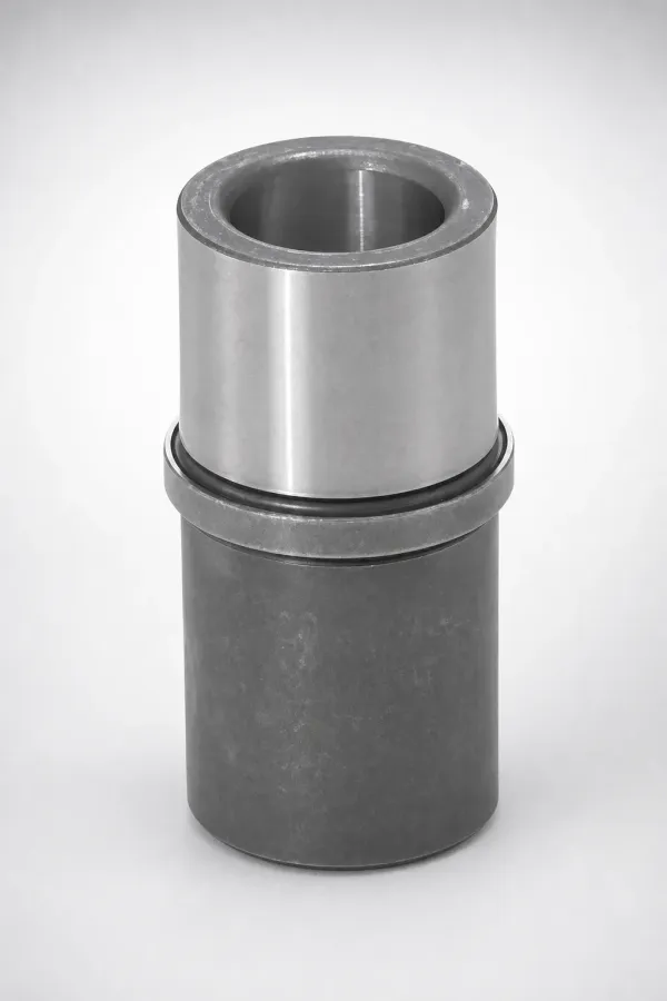
Fix the thermal map at the gate zone. For PC, hold the cavity near the gate at the grade window, typically 60-90°C, with baffles, bubblers or conformal cooling placed 8-12 mm from the surface. A cold gate zone freezes the crazed skin in place. A hot runner with a locally heated tip also smooths the stress spike and removes the frozen sprue problem from cold runner designs.
Tune gate freeze to the pack profile. Run a gate freeze study: step pack time until part weight stops rising, typically within 0.5-1 s of stability. If blush appears while pack is still pushing, the gate freezes too late relative to the skin. Smaller gate land or a thermal gate tip shortens the open window and caps the stress.
Steel and Coating Choices for Wear Resistance
Steel choice decides how long a polished surface stays scratch-free. For glass-filled service, pre-hardened P20 at HRC 28-32 is the budget option and typically shows wear within tens of thousands of shots. Through-hardened or quenched grades lift the number. H13 at HRC 48-52 and S136 at HRC 48-56 are common production choices, and DieStrike runs cavity heat treatment to HRC 62 for high-wear precision work. The grade trade-offs sit in our comparison of P20 vs H13 vs S136.
Hardness buys time, coatings buy distance. A DLC coating at 1-3 um thickness drops the friction coefficient to roughly 0.1 and raises surface hardness well above the substrate, so the part slides instead of plowing. Gas nitriding is the cheaper cousin for larger cores, adding a compound layer measured in hundreds of HV. Coatings do not fix bad draft or wrong polish direction, they extend the life of a geometry that is already correct.
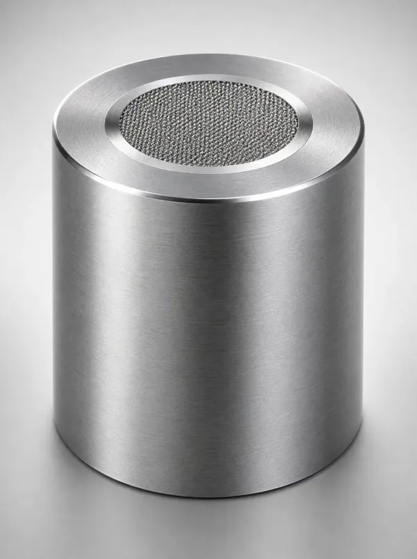
Specify the finish together with the steel. A hardened core polished to Ra 0.2 um along the draw, with DLC on the wear lands, is a typical package for connector molds running 30% GF resin at volumes above one million shots. Tolerances stay tight through the coating because DLC adds only 1-3 um, and a final light polish can trim it back where fits matter at ±0.002 mm.
Process Levers vs Mold Levers: Who Fixes What
Process can mask both defects, but only the mold fixes them permanently. Slower injection reduces shear at the gate and dims a halo for a few weeks until a hotter batch of resin brings it back. Extra polish hides drag marks until the steel wears again. The table below splits the levers by owner so a tooling buyer knows what belongs in the mold quote and what belongs in the process sheet.
| Root Cause | Mold-Side Fix (Permanent) | Process Band-Aid (Temporary) |
|---|---|---|
| Draft below 0.5 degree per side | Weld and re-machine core to 0.5-1.0 degree per side, or add slider | Raise mold temp, slow ejection speed |
| Polish against draw direction | Re-polish parallel to ejection, Ra 0.2-0.4 um typical | More mold release, which contaminates downstream |
| Soft steel worn by glass fibers | Hardened insert at HRC 48-62 or DLC coating 1-3 um | Frequent re-polish on a maintenance cycle |
| Undersized gate, shear too high | Enlarge gate or convert to fan, tab or submarine gate | Raise melt temp 5-10°C, cut injection speed |
| Gate jetting into a wall | Re-aim gate, add land or deflector | Slow first-stage fill profile |
| Cold cavity at gate zone | Conformal cooling or baffles 8-12 mm from surface | Higher mold temperature controller setpoint, longer cycle |
← swipe to scroll →
Table note: typical industry values for production injection molds. Actual limits depend on resin grade and part geometry.
The decision order stays the same on every program. Identify the defect by location and texture. Confirm with a process change, since only gate blush responds. Then fix the steel once, at design stage or in repair, instead of paying a process engineer to fight it every shift. A 24-hour DFM review before cutting steel is the cheapest place to catch all nine causes.
FAQ
Q1. Can die lines appear on textured surfaces?
Yes, and they are easier to see. Drag marks scrape the grain flat, leaving bright streaks where texture should be dull. Textured walls need extra draft, typically 1 degree additional per 0.01 mm of texture depth, because the grain bites into the part during ejection.
Q2. How do I fix gate blush on a clear PC lens?
Attack shear and thermal history together. Enlarge the gate or convert to a fan or tab gate, keep peak shear rate under the typical 40,000-60,000 1/s range for PC, and hold the cavity near the gate at 60-90°C. Then validate with a gate freeze study before locking the process.
Q3. Will a DLC coating stop drag marks by itself?
No. DLC at 1-3 um with a friction coefficient near 0.1 lowers ejection force and resists glass-fiber wear, but it cannot rescue a core with 0 degree draft or polish grooves running against the draw. Fix the geometry and finish first, then coat to extend life.
Q4. Which defect shows up first in a mold trial?
Usually gate blush, because T0 runs sweep fill speed and pack pressure and the halo responds immediately. Die lines often appear later, after thousands of shots wear a soft core or after the first texture application. Book both checks into T1 and T2 sign-off criteria.
Q5. Do die lines and gate blush ever share one root cause?
Rarely, but poor steel selection can drive both. A soft core that wears creates drag marks, and the worn rough surface raises local flow resistance that can stress the skin near the gate. Hardened steel at HRC 48-62 with the right coating cuts both risks.
The Bottom Line
Die lines are mechanical scratches from ejection. Gate blush is stress whitening from fill and pack. Location, texture and process response separate them in five minutes. The permanent fixes live in the tool: 0.5-1 degree of draft per side, polish along the draw at Ra 0.2-0.4 um, gates sized under shear limits, and hardened steel or DLC where glass fibers run. DieStrike builds IATF 16949 molds with HRC 62 cavities and ±0.002 mm geometry, and catches both failure modes in DFM review before steel is cut. Need a mold audit or repair quote? Reach the team through our contact page.
KEEP READING
Related Reading
Mold Polishing Guide: From Ra 3.2 to SPI A1
Surface finish specs by SPI grade, polish direction rules and the Ra values that keep parts releasing clean.
Read articleArticleDLC Coating for Mold Components
When DLC and nitriding pay off against glass-fiber wear, with typical hardness, thickness and friction data.
Read articleArticleHow to Prevent Ejector Pin Marks: 5 Root Causes
Ejection defects share tooling roots with die lines. Fix pin balance, clearance and polish before chasing process.
Read articleServiceMold Repair & Maintenance
Re-polish, re-machine and coating services that remove drag marks and gate stress from production tooling.
Read articleNEXT STEP
Ready to Start Your Mold?
Send us your element dimensions or part numbers — our team responds within 24 hours with pricing and lead time.

Written by
Ray ChanMold Buyer's Guide Author · Precision Mold Manufacturing Specialist. Ray helps global importers, distributors and OEMs source factory-direct molds and mold parts.