
Graphite vs Copper Electrodes for Sinker EDM: How to Choose
Table of Contents
A 64-cavity connector housing mold needed a 0.4 mm wide, 6 mm deep rib slot burned into a cavity insert hardened to HRC 62. The shop had roughed the open floor of that cavity with graphite, so the rib electrode was ordered in graphite too. The electrode edge chipped during machining, the burned slot opened from R0.05 mm to R0.18 mm, and the first 2,000 trial parts failed the rib check. Reburning with a copper electrode cost 6 extra days on a 3-week mold lead and added roughly 18% to the tooling bill.
Sinker EDM erodes a shaped electrode into hardened steel, one spark at a time. The discharge gap leaves an overcut of 0.02 mm to 0.5 mm per side depending on the operation, and every pass consumes a small part of the electrode itself. Graphite and copper are the two practical electrode families, and they differ in machining speed, wear, achievable finish and cost. A wrong pick is not one extra hour on a machine. It is a recut cavity, a missed trial date and a delivery window that slips past the customer's schedule.
The Snapshot
- Graphite mills 2 to 3 times faster than copper typical, with no burr and no coolant cleanup.
- Graphite holds roughing electrode wear to 0.2-0.5% typical at 20 A to 100 A burn current.
- Copper finishes to Ra 0.1-0.2 µm typical; fine-grain graphite reaches about Ra 0.3-0.4 µm.
- Copper ribs and walls hold below 0.3-0.5 mm wide; graphite chipping starts around that band.
- Graphite at 1.7-1.9 g/cm³ weighs about 80% less than copper at 8.9 g/cm³ for the same electrode volume.
The Rib That Missed T1
The post-mortem on that burn found three separate causes. Graphite was correct for the open floor above the rib, where a high-current roughing pass removed material fast and wore only about 0.3% of the burned depth. The same material failed at the rib itself, because a 0.4 mm wide graphite wall carries little bending strength and chips at the first handling bump. No generator setting recovers an electrode edge that is already gone.
The rework ran clean in copper. A machined copper electrode held the 0.4 mm rib, burned the slot within 0.02 mm of the print, and the cavity passed CMM on the second attempt. Copper cost more machining hours and a heavier material bill, but the program lost 6 days once instead of living with a geometry error for the life of the tool. That trade repeats on every mold that carries both an open floor and a fine detail in the same cavity.
The lesson is not that copper beats graphite. It is that electrode material must follow the feature, the burn phase and the electrode count. This guide walks the decision the way a mold shop runs it: material families, machining, wear, flushing and cost, then a feature-by-feature rule set. Every figure below is a typical industry value, and a shop should confirm critical numbers with a test burn before ordering 100 electrodes on one assumption.
What a Sinker Electrode Does Inside the Gap
Sinker EDM removes steel by localized melting, not by cutting. A pulsed generator drives current across the 0.02 mm to 0.5 mm gap, the dielectric oil breaks down, and each spark melts a microscopic crater out of the workpiece. Typical roughing runs at 20 A to 100 A with pulse-on times in the 100 µs to 1,000 µs range. Finishing drops toward a few amps with pulse-on times near 1 µs to 10 µs, and crater depth falls to 0.01 mm to 0.05 mm per spark train.
The electrode wears because the same sparks erode it. Front wear shortens the electrode, corner wear rounds its edges, and side wear widens the cut. Material removal in roughing commonly reaches 100 mm³/min to 300 mm³/min on modern generators. Finishing removes under 1 mm³/min, which is why surface quality and stock removal pull in opposite directions on the same cavity.
The burned surface carries a recast white layer, typically 2 µm to 20 µm thick. Hard, brittle and micro-cracked, it needs removal by polishing or a finishing pass wherever a cavity edge carries load or appearance. That layer is one reason electrode choice interacts with finish specifications on the mold print. It also separates sinker work from wire work, which our sinker EDM vs wire EDM comparison explains in process terms.
Both graphite and copper burn steel the same way. What changes is electrode loss, surface quality and the number of electrodes a cavity consumes. Those three outputs set machining cost, burn time and rework risk on every hardened insert that reaches the EDM cell at HRC 62.
Graphite Grades and Copper Alloys
Graphite for EDM is sold by grain size. Coarse grades with 10 µm to 20 µm particles rough fast and wear slowly but leave a coarse spark surface. Medium grades cover most general burns. Fine-grain grades in the 3 µm to 5 µm band are the finishing workhorses, and premium micro-grain grades go finer still for detail work. Price climbs as grain size falls, typically 1.5 to 3 times from a coarse block to a fine one.

Copper starts with electrolytic tough pitch grade C11000 at about 99.9% purity. C14500 tellurium copper carries 0.4% to 0.7% tellurium and machines without the gummy burrs of pure copper. Beryllium copper C17200 offers the stiffest thin walls, though its dust needs controlled ventilation during machining and grinding. Tungsten-copper blends with 70% to 80% tungsten appear when a 0.05 mm to 0.1 mm detail must hold through a long burn.
Density and conductivity sort the rest. Graphite sits at 1.7 g/cm³ to 1.9 g/cm³ against copper at 8.9 g/cm³, so the same electrode volume weighs about 80% less in graphite. Copper conducts heat 5 to 6 times better, which helps it hold fine detail at low current. Graphite resists erosion at far higher spark temperatures, which is why it carries high-current roughing without vanishing.
Machining the Electrode: Milling, Turning and Hand Work
Graphite machines fastest of the two by a wide margin. Mold shops report milling graphite 2 to 3 times faster than copper at the same detail, with dry cutting, no burrs and no coolant cleanup. Diamond-coated end mills running at 10,000 rpm to 30,000 rpm are standard tooling, and the fine dust goes to an extraction system sized for respirable particles. An electrode set that takes 6 h in copper often takes 2 h to 3 h in graphite.
Copper needs slower milling with coolant plus a deburr pass on every edge. Round electrodes turn on a lathe, which brittle graphite cannot do in the same way. Copper also accepts hand work, and a skilled fitter can file or scrape 0.02 mm to 0.05 mm off a copper electrode to correct a worn corner. Graphite does not tolerate that touch-up path at all.

Thin walls set the machining boundary. Graphite ribs below roughly 0.3 mm to 0.5 mm wide chip during cutting and handling, because the material fractures instead of bending. Copper ribs hold down to about 0.1 mm to 0.3 mm and bend rather than snap. If an electrode print shows a wall under 0.5 mm, most shops move that electrode to copper before the CAM file is written.
Electrode machining follows the same discipline as any mold component. Tool offsets, feature compensation and CMM checks apply to the electrode exactly as they apply to the cavity it burns. The rules that hold mold components to ±0.002 mm and molds to ±0.005 mm start at the electrode blank, which is the ground our precision CNC machining for mold components guide covers.
Graphite vs Copper at a Glance
One table cannot set every burn, but it frames the trade-offs that repeat on every job. Values below are typical shop-floor figures from EDM practice. Machine, generator and electrode supplier can each shift a number by 20% to 30%, so confirm the critical rows on your own equipment before a large electrode order.
| Property, typical | Graphite | Copper |
|---|---|---|
| Density | 1.7-1.9 g/cm³ | 8.9 g/cm³ |
| Electrode milling speed | 2-3x faster, dry, no burr | Slower, coolant, deburr step |
| Thin ribs and walls | Chip below ~0.3-0.5 mm | Hold 0.1-0.3 mm typical |
| Roughing electrode wear | 0.2-0.5% typical at high current | Higher at the same current |
| Best typical finish | Ra 0.3-0.4 µm, fine grain | Ra 0.1-0.2 µm |
| Inside corner at finish | Rounds sooner | Holds R0.05-0.1 mm typical |
| Hand dressing | Not practical | Files and scrapes 0.02-0.05 mm |
| Debris in the gap | Fine powder | Heavier particles |
| Weight per electrode | ~80% lighter | Full copper mass |
← swipe to scroll →
Table note: Typical published EDM practice and shop experience. Generator settings, grade and geometry shift each band, so verify the critical rows with a test burn on your machine.
Read the rows as a decision filter, not a scorecard. Graphite wins wherever volume, roughing and electrode count dominate the job. Copper wins wherever a thin wall, a sharp corner or a mirror finish sits on the print. The next sections attach working numbers to each row.
Roughing Big Cavities and Managing Wear
Roughing is graphite territory. At 20 A to 100 A, graphite holds electrode wear to 0.2% to 0.5% of the burned depth, typical. Burn a pocket 20 mm deep and the electrode shortens 0.04 mm to 0.1 mm, an offset the program absorbs before the burn starts. Copper at the same current erodes faster, and deep roughing often needs a second electrode before the cavity floor is reached.
Current density explains the split. Graphite survives the spark temperature at high current with low erosion, while copper's high thermal conductivity pulls energy away from the cut and drives wear up as current climbs. The practical effect shows in burn time. A deep pocket that burns in 8 h with graphite commonly needs 10 h to 12 h with copper to reach the same floor at the same finish target.
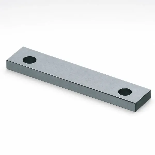
Weight reinforces the choice on big electrodes. A roughing block 300 mm by 150 mm by 60 mm holds 2,700 cm³ of material, which is 24 kg in copper at 8.9 g/cm³. The same block in graphite at 1.8 g/cm³ weighs about 4.9 kg. Workhead capacity, rack handling and setup time all follow that 19 kg difference per block.
Cavity count multiplies the effect. A 16-cavity burn with one roughing electrode per cavity lifts that mass at every index. Tools for connector housings run 32 to 64 cavities, and shops serving connector OEMs including TE Connectivity, Amphenol and Luxshare buy graphite roughing sets partly so the electrode logistics stay manageable through the whole burn sequence.
Finishing Surface, Ribs and Corners
Finishing reverses the ranking. Copper delivers the best sinker surface, reaching Ra 0.1 µm to 0.2 µm with low current, short pulses and spark-out passes. Fine-grain graphite lands near Ra 0.3 µm to 0.4 µm under the same conditions. For a cavity that will polish to a mirror, copper starts closer to the target, and the polisher removes less steel to reach the final grade.
Corners and ribs decide more often than average roughness does. Graphite rounds at the working edge as the burn progresses, so a sharp inside corner asks for copper, which holds a radius near R0.05 mm to R0.1 mm typical. Thin ribs follow the machining limits from the earlier section. Below about 0.5 mm wide, copper is the safer burn on both counts.
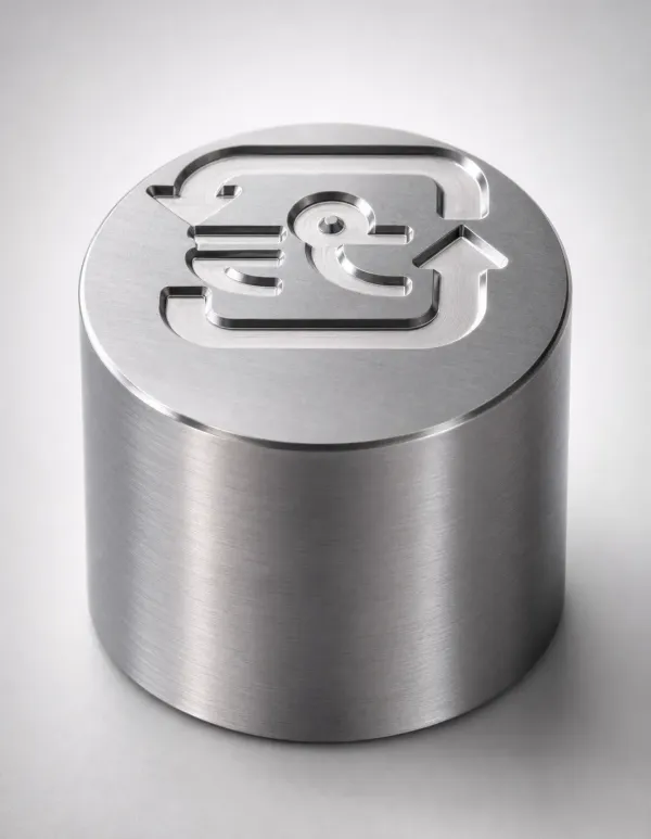
Fine detail behaves like ribs. Raised letters 0.2 mm to 0.4 mm wide burn cleanly from a copper electrode, and a choked letter can be hand dressed back to shape. Fine-grain graphite burns the same text only when the electrode survives machining, which at that width is not guaranteed. That single fact kills more graphite finishing quotes than any roughness argument.
There is a ceiling worth naming. If the print demands a high-gloss or optically clear surface, sinker EDM is usually the wrong final step altogether. The burn leaves a recast layer 2 µm to 20 µm thick, and removing it without losing geometry is a polishing problem. Where hard milling can hold the corner, it skips the layer entirely, and our hard milling vs EDM guide weighs that choice with numbers.
Wear Compensation and Electrode Sets
Wear compensation starts with a number no supplier hands you. The wear ratio moves with current, pulse-on time, polarity, flushing and electrode material, so shops measure it. A typical test burns a coupon 5 mm to 10 mm deep, reads the front and corner loss, and feeds the offset into the CAM file from that measured data instead of a catalog guess.
Overcut sizes the electrode. A roughing electrode is undersized by the 0.1 mm to 0.5 mm gap typical of high-current work. Semi-finish runs at 0.05 mm to 0.15 mm per side. A finish electrode carries 0.02 mm to 0.05 mm per side and should remove no more than 0.1 mm of stock, because its own wear shows on the part past that point.
Electrode count follows the burn phases. Most cavities run two to three electrodes: one rough, one semi-finish, one finish. A 32-cavity mold with two details per cavity therefore consumes 128 to 192 electrodes. That arithmetic is why graphite dominates high-cavity tools, since milling 150 identical electrodes 2 to 3 times faster moves the program schedule by days, not hours.
Copper earns its place at the finish stage. If a finish burn drifts 0.02 mm out of tolerance, a fitter dresses the copper electrode and burns again. Graphite would need a full CNC recut for the same correction. Small rework loops matter most near the end of a 2-5 week mold lead, when the schedule carries no slack left to absorb a second electrode cycle.
Flushing and Debris in the Gap
Every spark throws debris into the gap, and that debris must clear before the next spark arrives. Sinker machines flush dielectric oil at 0.05 MPa to 0.4 MPa typical, through electrode holes, from the side, or by orbiting the electrode. Gap widths of 0.02 mm to 0.5 mm leave little room, so flushing quality sets both the practical burn speed and the reachable finish.
The two materials shed different debris. Graphite erodes into a fine powder that rides the oil flow easily but packs into deep narrow slots when pressure drops. Copper throws heavier particles that settle fast and need directed flow. Both failure modes look the same downstream: secondary sparks, rounded corners and a finish 2 to 3 Ra classes coarser than the generator should produce at those settings.
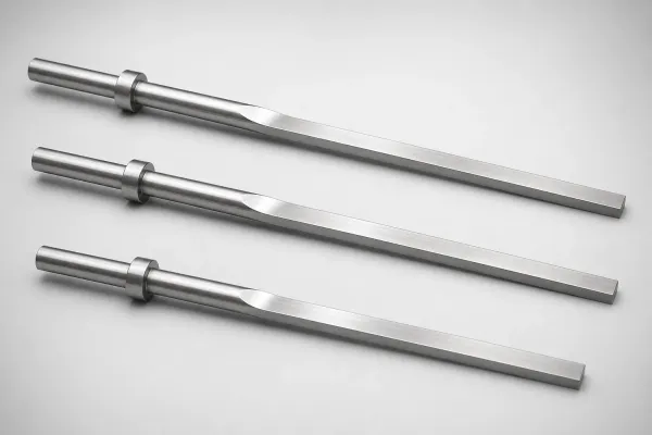
Electrode design should plan the flush path before the burn starts. Through-holes of 0.5 mm to 2.0 mm diameter in the electrode deliver oil to the floor of a deep pocket. Where a feature is too narrow for holes, orbiting the electrode by 0.05 mm to 0.2 mm pumps the gap mechanically and clears the debris between passes.
Pressure also flexes thin electrodes. A copper rib 0.2 mm wide deflects under a 0.3 MPa side flow, and a graphite wall that thin is already gone before flushing starts. Burners cut pressure or switch to pulse flushing on fine work, trading speed for geometry. When the part offers a through slot, wire EDM skips the closed-cavity flushing problem entirely, as covered in our wire EDM for mold making guide.
Cost, Lead Time and Shop-Floor Reality
Material cost lands in graphite's favor per electrode. EDM graphite blocks cost more per kilogram than copper, but the electrode weighs about 80% less, so the per-part material bill is typically lower. Fine and micro-grain grades cost the most per kilogram, which is why shops stock a coarse grade for roughing sets and a fine grade for detail work.
Machining hours decide the rest of the ledger. Graphite cuts 2 to 3 times faster with no deburr step, but it needs an enclosed machine, dust extraction and filter maintenance. Copper machines slower, makes burrs and handles coolant, yet its swarf is clean scrap with resale value. A one-off cavity electrode can land cheaper in copper. A 150-electrode set lands cheaper in graphite on hours alone.

Lead time is where the decision reaches the customer. Electrode design and machining normally sit inside the first week of a 2-5 week injection mold program, running parallel to cavity milling. Faster electrode machining does not shorten the mold by the same number of days unless EDM sits on the critical path. It shortens the risk that EDM becomes the critical path when a first electrode fails inspection.
Buyers rarely see the electrode ledger, but they feel it in the quote and the delivery date. Mold makers price electrode material, machining hours and expected rework into every tool. A shop that burns everything in copper pays in roughing hours. One that burns everything in graphite carries thin-rib risk. Ask which features drove the electrode plan, and you learn where the margin in your quote went.
Decision Rules by Mold Feature
Feature-by-feature beats material-by-material. The matrix below is the working rule set most mold shops apply, with the first choice and the number that explains it. Verify the thin-wall and finish bands against your machine, generator and electrode supplier before ordering a large electrode batch.
| Decision driver | First choice | Why (typical figures) |
|---|---|---|
| Open cavity floor, heavy roughing | Coarse graphite | 0.2-0.5% wear at 20-100 A, fewer electrodes |
| Ribs and slots below 0.5 mm wide | Copper | Holds 0.1-0.3 mm; graphite chips near 0.5 mm |
| Mirror or high-gloss band | Copper | Ra 0.1-0.2 µm vs 0.3-0.4 µm fine graphite |
| Inside corners at R0.1 mm or less | Copper | Corner retention at low current |
| Text, logos, fine engraving | Copper or fine graphite | Copper hand-dressable; 3-5 µm graphite at volume |
| 16-64 identical cavities | Graphite | Mills 2-3x faster; 128-192 electrode sets |
| Very large electrode mass | Graphite | ~80% lighter, workhead and rack friendly |
| Late-stage correction burns | Copper | Dress 0.02-0.05 mm and re-burn without a recut |
← swipe to scroll →
Table note: Typical shop guidance. A DFM review of the actual cavity overrides any generic matrix, and a test burn sets the final offsets for your machine and material combination.
Order the decision by the feature that fails first. A cavity with one 0.3 mm rib and a large open floor takes graphite for the roughing electrode and copper for the finish burn, and mixed-material sets are completely normal. The plan belongs in the DFM review before steel is cut. Finding out at the EDM machine that the electrode material was wrong burns the schedule, not just the electrode.
FAQ: Graphite vs Copper Sinker EDM Electrodes
Q1. When should I choose graphite for a sinker EDM electrode?
Choose graphite when the burn is large, rough or repeated. It mills 2 to 3 times faster than copper, holds roughing wear to 0.2-0.5% typical at 20 A to 100 A, and its density near 1.8 g/cm³ keeps big electrode racks manageable. High-cavity connector and consumer electronics molds lean graphite for exactly these reasons.
Q2. When does copper win over graphite?
Copper wins on geometry that graphite cannot hold. Ribs and walls below roughly 0.3 mm to 0.5 mm, inside corners near R0.05 mm to R0.1 mm, and finish surfaces at Ra 0.1 µm to 0.2 µm all favor copper. Its ductility also allows hand dressing corrections of 0.02 mm to 0.05 mm without a full CNC recut.
Q3. Can graphite burn a mirror finish?
Fine-grain graphite in the 3 µm to 5 µm class reaches about Ra 0.3 µm to 0.4 µm typical, which is bright but not mirror. True mirror bands below about Ra 0.1 µm to 0.2 µm usually burn with copper, because the burn itself leaves a 2 µm to 20 µm recast layer that polishing must remove afterward.
Q4. How many electrodes does one cavity need?
Plan two to three per detail: rough, semi-finish and finish. Offsets run 0.1 mm to 0.5 mm per side for roughing and 0.02 mm to 0.05 mm per side for finishing. A 32-cavity tool with two details can pass 128 to 192 electrodes, which is why electrode machining speed dominates high-cavity program planning.
Q5. Does electrode material change the spark gap or overcut?
The overcut is set by generator parameters, not by material alone, but wear changes the net offset you program. Roughing gaps of 0.1 mm to 0.5 mm per side are typical for both materials. Run a test burn 5 mm to 10 mm deep on a witness block and measure front and corner wear before you commit 100 electrodes to a single offset value.
The Bottom Line
Pick graphite for big roughing, high cavity counts and volume work. Pick copper for thin ribs, sharp corners and mirror finishes. Confirm wear and finish with a test burn before the electrode order. The wrong material recuts cavities, burns schedule and turns a 2-5 week mold lead into a six-week apology.
DieStrike is an IATF 16949 certified precision mold manufacturer with over 120 machines. Mold accuracy holds to ±0.005 mm, mold component geometry to ±0.002 mm, and cavities are heat treated to HRC 62 for connector OEMs including TE Connectivity, Amphenol and Luxshare. Injection molds ship in 2 to 5 weeks. Discuss your electrode plan and cavity geometry with our engineers at contact us.
KEEP READING
Related Reading
Wire EDM for Mold Making: Accuracy, Surface, and Cost
Wire EDM trims hardened inserts with no electrode wear: ±0.002 mm class cuts, recast layer control, and when a through-cut beats a closed cavity burn.
Read articleArticleHard Milling vs EDM for Mold Finishing: How to Choose
Corner radius, finish and white layer decide the process. Hard milling avoids the 2 to 20 µm recast layer that every EDM burn leaves on HRC 62 steel.
Read articleArticlePrecision CNC Machining for Mold Components
Electrode and cavity machining share the same discipline: ±0.005 mm mold accuracy, ±0.002 mm components, CMM verified before the burn starts.
Read articleServiceInjection Mold Manufacturing
Precision injection molds under IATF 16949 with ±0.005 mm cavity accuracy, HRC 62 hardened inserts and 2-5 week lead times for connector OEMs.
Read articleNEXT STEP
Ready to Start Your Mold?
Send us your element dimensions or part numbers — our team responds within 24 hours with pricing and lead time.

Written by
Ray ChanMold Buyer's Guide Author · Precision Mold Manufacturing Specialist. Ray helps global importers, distributors and OEMs source factory-direct molds and mold parts.