
How to Calculate Ejection Force and Size Ejector Pins
Table of Contents
A four pin layout on a 120 mm ABS housing buckled during the first production order. The two outer 6 mm pins had a 65 mm unsupported length, each carried close to 18 kN, and both bent within 9,000 shots. The tool left the press for two days while new pins were fitted and the ejector plate was re-cut. That stoppage pushed the launch back four days and added about 6,000 USD of machining and lost press time.
Ejection force is arithmetic that can be done before the first cut. This guide covers the four terms, a worked example and the buckling check that sets pin count.
The Snapshot
- Grip pressure sets the force. Contact pressure runs 3 to 6 MPa for unfilled PP and 8 to 15 MPa for PA66-GF30 on a 50 mm core. That single term dominates most estimates.
- Vacuum is never free. A flat blind face with no air break pulls 0.1 MPa, so a 100 x 100 mm plate alone adds 1 kN of release force.
- Texture nearly doubles the pull. A mirror core runs a friction coefficient of 0.15 to 0.20, while an SPI D3 texture runs 0.35 to 0.50 on the same geometry.
- Pins fail in bending. A 6 mm pin with a 40 mm free length buckles at 12 to 20 kN. Force per pin decides the layout, not pin diameter on its own.
What Holds the Part on the Core
Three resistances hold a molding on the core, and they add. The part grips the steel because it shrank onto it during cooling. It sticks to a flat face because air cannot get behind it in time. Every square millimeter of that contact also carries friction.
Part weight is the wrong variable to design from. A 200 g housing with deep core-side walls can need 45 kN of release force. A 200 g flat lid with a 1 mm skirt needs under 3 kN, and both parts weigh the same.
Contact area decides the answer, and contact area is a tooling decision. Draft angle, polish direction, core-side texture and pin placement all change how much of the part still presses on steel when the ejector plate moves. The plate architecture itself is covered in the ejector system design guide.

The three terms scale at different rates. Grip pressure scales with modulus and shrinkage. Vacuum pull scales with flat area that has no air break. Friction scales with the texture on the sliding face. That is why one rule of thumb never fits a whole product family.
One further term sits outside the physics. A part ejected at 60 °C grips harder than the same part ejected at 95 °C, because the modulus climbs as the temperature falls. The ejection setpoint is part of the calculation, not a process afterthought.
Shrinkage Grip and Interface Pressure
Shrinkage grip is the largest term in most tools. As the melt cools on the core it contracts, and because the steel does not move, the part builds contact pressure against the core wall. A first-order estimate uses the elastic relation p = E x dS / (1 - v).
E is the resin modulus at ejection temperature, dS is the linear mold shrinkage and v is Poisson ratio, normally 0.35 to 0.45. The modulus is the term most often taken from the wrong column of a datasheet. At ejection temperature it is only 10 to 40 percent of the room-temperature value.
Two cases show the spread. A 50 mm core in PA66-GF30 with 0.4 percent shrinkage lands at 8 to 15 MPa of contact pressure. The same core in unfilled PP with 1.5 percent shrinkage lands at 3 to 6 MPa, because the softer matrix offsets the larger contraction. Published shrinkage bands are useful here, and the shrinkage compensation rules explain how to convert them into cavity dimensions.
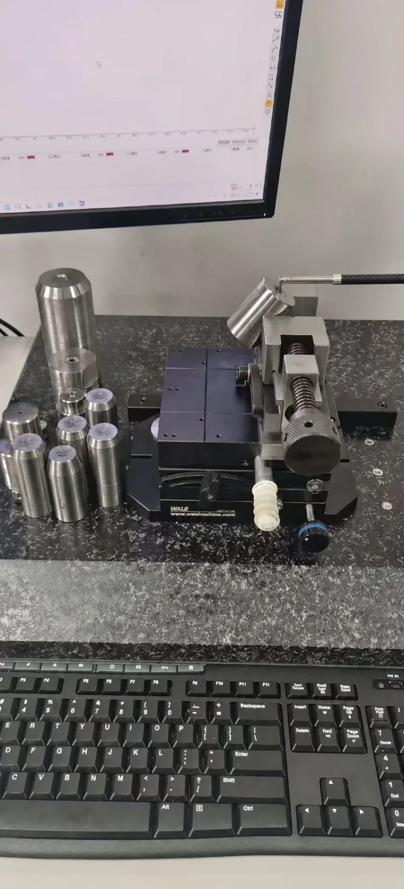
Core-side cooling moves the number by a factor of two or more. A wall that runs 30 °C colder than its neighbor has already stiffened, and it grips harder at the moment of ejection. Warmer ejection lowers both the release force and the pin mark depth, so the two decisions belong together.
Vacuum Pull, Friction and Texture
A flat core face with no air break behaves like a suction cup. Atmospheric pressure adds 0.101 MPa over the trapped area. That is 1 kN on a 100 x 100 mm face and 10 kN on a 320 x 320 mm face. That force exists only while the seal holds.
Air breaks are the cheapest fix in the whole ejection system. A 0.5 mm vent ground through an ejector pin cuts the vacuum term to near zero. A 0.02 to 0.05 mm vent land beside it does the same within a millimeter of travel.
Friction is the multiplier on grip pressure. A mirror-polished core that runs along the draw direction gives a coefficient of 0.15 to 0.20. An SPI D3 texture across the same draw gives 0.35 to 0.50, which roughly doubles the force for identical geometry and identical shrinkage.
Polish direction matters as much as roughness. A core polished across the draw creates 0.5 to 2 µm ridges that the part has to climb. Polish marks that run along the draw direction remove most of that resistance and cost nothing extra at the bench.
Draft angle is the other lever. A core with 0.5 degrees of draft keeps contact along the whole wall. A core with 2 degrees releases the wall after 1 to 2 mm of travel, and the friction term falls away for the rest of the stroke.
The Ejection Force Formula
The working relation is F = mu x p x A + F_vacuum + margin. Every term carries a unit, and mixing millimeters with meters is the most common arithmetic error in a hand calculation.
A_contact is the area the part still grips on the core at release, not the projected area of the molding. A 120 x 80 mm box has 9,600 mm2 of projected area and roughly 25,000 mm2 of core contact once walls, ribs and bosses are counted.
Add the terms in newtons and convert once at the end. 1 MPa over 1 mm2 is 1 N, so a pressure in MPa multiplied by an area in mm2 already returns newtons.
The margin is a safety factor on the total, and 1.3 to 1.5 is normal for a design calculation. It covers resin lot variation, a colder-than-planned ejection temperature and the stiffening that shows up on the first shots in a cold tool.
Do not stack a second factor on top for shock. The ejector plate moves at 20 to 80 mm/s and the load is close to static over that range. Doubling the safety factor instead of fixing the geometry produces a heavy plate that still marks the part.
Worked Example: 120 mm ABS Box
The part is an ABS box, 120 mm x 80 mm x 40 mm deep, gated on the cavity side with the walls and four bosses on the core. Core-side contact area is 25,000 mm2. The core runs at 60 °C and ejection starts at 88 °C.
Contact pressure for ABS on this core is 6 MPa, taken from the shrinkage estimate and confirmed against the first-shot force. The friction coefficient on a polished, along-draw core face is 0.2.
The grip term is 0.2 x 6 MPa x 25,000 mm2, which is 30,000 N, or 30 kN. That one term is 98 percent of the answer, which is normal for a part of this depth.
Vacuum comes next. Four 0.5 mm air-break vents through the ejector pins cover the flat core face. The trapped area falls to about 8,000 mm2 and the vacuum term drops under 0.5 kN. A fully sealed face of the same size would add 0.8 kN.
Total release force lands at roughly 30.5 kN. Applying a 1.5 safety factor gives 45 kN, and that is the number the ejector system has to carry.
| Term | Calculation | Result | Share of total |
|---|---|---|---|
| Shrinkage grip friction | 0.2 x 6 MPa x 25,000 mm2 | 30.0 kN | 98 percent |
| Vacuum on the flat core face | 0.1 MPa over 8,000 mm2 with four air breaks | 0.5 kN | 2 percent |
| Static release total | grip plus vacuum | 30.5 kN | 100 percent |
| Design force | 30.5 kN x 1.5 safety factor | 45.8 kN | Sizing number |
← swipe to scroll →
Table note: these values belong to the worked example in this section. Confirm contact pressure and the friction coefficient against the first-shot measurement before the pin pattern is finalized.
The estimate is deliberately conservative. Real release is progressive, so the part peels off the core over 1 to 3 mm of travel instead of breaking away at once. Measured force on tools of this size commonly runs 30 to 60 percent of the calculated number. That is what the verification step later in this guide is for.
Ejector Pin Sizing and Buckling
An ejector pin is a slender column, so the failure mode to check is buckling rather than compression. The Euler relation gives the critical load as F_cr = pi^2 x E x I / (k x L)^2. Here I is the second moment of area and L is the unsupported length.
Second moment of area scales with diameter to the fourth power, and buckling load falls with the square of the free length. Going from 6 mm to 8 mm multiplies capacity by 3.2, while stretching the free length from 40 mm to 80 mm removes 75 percent of it.
Shop data for a hardened pin at HRC 55 to 60 with a 1.5 mm head land sets a 6 mm pin at 12 to 20 kN. That holds when the unsupported length is 40 mm. That sits below what a perfect Euler column predicts, so the effective length factor belongs at 2.0 or higher rather than at 1.0.

A pin face never carries load evenly. Off-center loading from a corner boss, plus clearance in the ejector plate bore, adds bending that the Euler check does not see. Holding the working load at one third to one half of the buckle load keeps that margin.
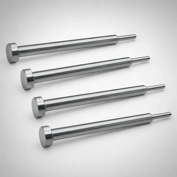
Head land geometry matters as much as diameter. A pin with a flat 1.5 mm land spreads contact and resists peening at HRC 55 to 60. A full-radius head concentrates pressure and marks the part at roughly a third of that load. The ejector pin range lists the land options by diameter and length.
| Pin diameter | 40 mm free length | 60 mm free length | 80 mm free length |
|---|---|---|---|
| 4 mm | 2.5 to 4 kN | 1 to 2 kN | Under 1 kN |
| 6 mm | 12 to 20 kN | 5 to 9 kN | 3 to 5 kN |
| 8 mm | 38 to 63 kN | 17 to 28 kN | 9 to 16 kN |
| 10 mm | 92 to 150 kN | 41 to 68 kN | 23 to 38 kN |
| 12 mm | 192 to 320 kN | 85 to 142 kN | 48 to 80 kN |
← swipe to scroll →
Table note: buckling loads are scaled from a shop-verified 6 mm pin at a 40 mm free length of 12 to 20 kN. Scaling uses the fourth power of diameter and the square of the free length. An effective length factor near 2 applies. Confirm against the pin supplier data and the first-shot measurement.
Pin length is usually set by the plate stack, not by choice. Reducing the unsupported length with a guided bushing or a thicker support plate is often the cheaper fix. Capacity rises with the square of the length change, not the fourth power of the diameter.
Pin Count, Diameter and Layout
Divide the design force by the allowable load per pin to get a count. For the ABS box at 45 kN, an 8 mm pin on a 40 mm free length carries 12 to 31 kN as a working load. A 6 mm pin carries 4 to 10 kN.
Six pins of 6 to 8 mm therefore cover the load, with 7.6 kN per pin on a six pin layout at the 8 mm size. That is inside the buckling envelope with a factor above 1.5 on the conservative end of the range.
Two 10 mm pins are the wrong answer, even though the Euler check would pass them. Each would carry 22.9 kN. That is above the 8 to 15 kN a 1.5 mm head land takes before it peens. It is also far above the pressure a visible wall tolerates.
Pin count also has a floor set by the part rather than by the force. A wall under 1.5 mm, a rib 3 mm wide or a boss under 8 mm across cannot take a pin without a mark. The load has to move to regions that can carry it.
Layout follows four rules. Put pins at the corners of a box, at the base of ribs, at the center of bosses, and along long unsupported edges every 80 to 120 mm. Balance the pattern around the center of pressure so the plate does not tilt as it moves.
Then check the face pressure, because it is the gate that most layouts miss. Spreading 45 kN over six 8 mm pins gives 7.6 kN per pin, which is 150 MPa across a 50 mm2 pin face. A visible wall tolerates roughly 5 to 10 MPa, so this part needs a stripper plate on the class A face with pins only on hidden lands.
The general rule that follows from that number: keep the combined pin and sleeve face area at 10 to 20 percent of the core contact area. For this box that is 2,500 to 5,000 mm2 of face area, and 45 kN over 5,000 mm2 gives 9 MPa, inside the visible-face limit.
When Pins Cannot Win
Three geometries send the ejection system away from round pins. They are walls under 1.5 mm, class A faces that cannot show a mark, and boxes deeper than 60 mm. All three exceed what a pin face can carry without damage. The guide to preventing pin marks covers the cosmetic side in more detail.
A stripper plate is the standard answer for the first two cases. It pushes on the full perimeter, so the same 45 kN spreads over thousands of square millimeters instead of a few hundred. The plate needs 3 to 5 mm of guided travel and its own return springs.
Ejector sleeves work where a pin has to pass through a boss. A sleeve with a 4 mm bore and a 7 mm outer diameter carries the same load over three times the face area. It also vents the bore it passes through.
Air ejection handles the deep box. A 0.3 to 0.8 MPa pulse through a porous insert or a drilled core breaks the vacuum. It lifts the part 0.5 to 2 mm before any mechanical contact. That removes the peak force from the pins entirely.
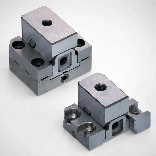
Combination systems are common on deep parts: air to break the seal, a two-stage plate to move 1 to 3 mm, then pins to finish the stroke. Each stage adds cost, so the choice should follow the force and the mark limit rather than shop habit.
Ejector Plate Design and Two-Stage Ejection
The ejector plate has to deliver the calculated force without flexing. Plate thickness, guide pillar placement and the number of return springs all follow from the load. A 45 kN load is enough to bend a 15 mm plate across a 250 mm span.
Two-stage ejection splits the stroke into two movements. The first stage moves 1 to 3 mm at low force to break the vacuum and the grip, and the second stage completes the travel. Mark depth falls 40 to 70 percent because the first stage acts while the part is still warm and elastic.
Timing is part of the force. A tool that waits 10 seconds after opening runs 30 to 40 °C colder on the core. The modulus at that temperature can double the grip term. On the ABS box above, that delay alone would take the design force past 60 kN.
Return springs must be sized for the plate plus the pin load, not for the plate alone. An under-sized spring lets the plate lag on closing, which is how pins get bent on a fast close rather than on ejection.
Guiding is not optional on a plate carrying 45 kN. Use two guide pillars as a minimum and four on a plate over 400 mm wide, with 0.02 to 0.05 mm of clearance in hardened bushings.
Verifying Force on the First Shots
The calculation is an estimate, and the first shots are the measurement. A strain gauge on an ejector tie bar or a load cell under the ejector plate reads the real force within about 5 percent.
Log the peak force against shot number for the first 200 shots. A force that climbs 20 percent over 50 shots points to a cooling problem or a core that is picking up. A force that stays flat means the estimate was close.

Measure at two ejection temperatures. Running the tool 10 °C cooler gives a clean comparison of the modulus effect. The gap between the two curves is the number to use for the production setpoint.
If the measured force is above the design value, the fix order is cooling first, draft second, texture third and pin count last. Adding pins to a hot core hides the problem and moves the damage from the pins into the part.
Record the result in the tool file with the ejection temperature, the shot number and the plate speed. That entry turns the next calculation on the same part family into a checked number instead of a fresh estimate. DieStrike runs this calculation during DFM on injection mold manufacturing projects and confirms it on the T1 trial.
Ejection Force Calculation FAQ
Q1. What is the formula for ejection force?
F = mu x p x A + F_vacuum, with the total multiplied by 1.3 to 1.5. Here mu is the friction coefficient, p is the contact pressure from shrinkage, and A is the core contact area the part still grips at release.
Q2. What contact pressure should I use for shrinkage grip?
3 to 6 MPa for unfilled PP and 8 to 15 MPa for PA66-GF30 on a 50 mm core. Compute it from p = E x dS / (1 - v). Use the modulus at ejection temperature, which is 10 to 40 percent of the room-temperature value.
Q3. How many ejector pins do I need?
Divide the design force by the allowable load per pin, which is one third to one half of the buckling load. An 8 mm pin on a 40 mm free length works at 12 to 31 kN. A 45 kN job therefore lands between 2 and 11 pins depending on diameter and free length.
Q4. Why do my ejector pins bend instead of the part releasing?
Either the free length is too long or the load per pin is too high. Buckling falls with the square of the free length. A 6 mm pin at 80 mm carries about a quarter of the load it carries at 40 mm.
Q5. When should I use a stripper plate instead of pins?
When the wall is under 1.5 mm, the face is class A, or the box is deeper than 60 mm. Pin face pressure above 5 to 10 MPa on a visible surface marks the part no matter how the pins are timed.
The Bottom Line
Four numbers decide an ejector system. They are the contact pressure from shrinkage, the friction coefficient from texture, and the vacuum term from a flat area with no air break. The fourth is the pin buckling load at its real free length.
For the ABS box in this guide, that arithmetic gives 30 kN of grip friction, 0.5 kN of vacuum and a 45 kN design force. Six 8 mm pins cover the load. The visible face still needs a stripper plate, because 150 MPa at a pin face is far above what a class A wall will take.
DieStrike builds precision injection molds to IATF 16949 with +/-0.005 mm mold tolerance and +/-0.002 mm on EDM and jig-ground features. Cavity heat treatment reaches HRC 62, and the shop runs 120+ machines. Standard components ship in 3 to 7 days and tool lead times run 2 to 5 weeks. Ejector systems on tier-1 programs for TE, Amphenol, Luxshare and Dongshan are sized from the calculation shown here before any plate is cut.
KEEP READING
Related Reading
How to Design Ejector Systems
Plate architecture, pin layout and the travel numbers that keep a molding square on release.
Read articleArticleHow to Prevent Parts Sticking to the Mold
Vacuum, draft and texture fixes for the sticking force that pins are asked to remove.
Read articleArticleHow to Prevent Ejector Pin Marks
Contact pressure limits, head land choice and timing that stop witness marks on visible walls.
Read articleServiceInjection Mold Manufacturing
IATF 16949 mold building with +/-0.005 mm accuracy, ejector system calculation and 2 to 5 week lead times.
Read articleNEXT STEP
Ready to Start Your Mold?
Send us your element dimensions or part numbers — our team responds within 24 hours with pricing and lead time.

Written by
Ray ChanMold Buyer's Guide Author · Precision Mold Manufacturing Specialist. Ray helps global importers, distributors and OEMs source factory-direct molds and mold parts.