
How to Design Hydroforming Dies: Pressure, Seals and Tooling
Table of Contents
A hydroforming cell that bursts a 1.5 mm aluminum battery tray at 120 MPa rarely has a pressure problem. It has a 0.15 mm extrusion gap the seal designer left open. That gap costs days of press time, a re-cut seal groove and a launch program waiting on parts. Fluid pressure replaces the punch here, so the cavity die carries only half of the forming physics. The other half lives in seals, the pad or membrane, the vents and the blank, and this guide sets those numbers out.
Every figure below is a typical industry value for sheet and tube hydroforming tooling, and each one needs checking against the press datasheet and the alloy before a drawing is released.
The Snapshot
- Draw ratio of 2.0 to 2.6 versus 1.8 to 2.1. Pressure forms the blank with no punch contact, so one hydroforming pull reaches depths that need two or three draw stations on a rigid punch.
- Forming pressure of 20 to 150 MPa on sheet, 100 to 400 bar on tube. Sheet hydroforming pushes with fluid or a membrane, and tube hydroforming adds axial feed to internal pressure.
- Seal extrusion gap under 0.10 mm. Polyurethane seals die at 80 to 150 MPa once the gap to the pad opens past that line. The groove runs 2 to 3 mm wide by 1.5 to 2 mm deep.
- Tool cost of 15,000 to 60,000 USD for one cavity. A matched draw die set for the same part runs 40,000 to 150,000 USD. A hydroforming cycle costs 60 to 300 seconds against 5 to 15 seconds on a press.
What Hydroforming Replaces with Pressure
Hydroforming forms sheet metal or tube against a female cavity die. Pressurized fluid replaces the matched punch. The fluid, hydraulic oil or water, presses the blank into every corner of the cavity. There is no punch nose entering the die, so no punch radius wears and no punch-to-die clearance has to be set.
Sheet hydroforming runs at 20 to 150 MPa. A diaphragm or a direct fluid pad loads the blank over the cavity. The part pulls into depths a rigid punch cannot reach without ironing or splitting. Typical work is 0.5 to 3 mm aluminum and stainless: sink bowls, appliance panels, EV battery trays, exhaust shields and cosmetic covers.
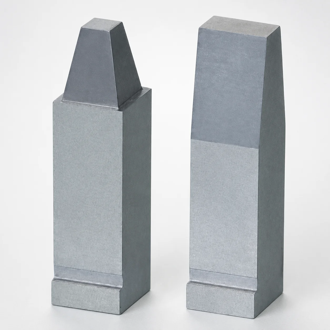
Tube hydroforming runs differently. A pre-bent tube is clamped between two end plugs and sealed. The chamber is filled and pressurized to 100 to 400 bar. Hydraulic rams push the tube ends inward at the same time. That axial feed keeps the wall from thinning to burst. Parts include exhaust manifolds, roll bars, bicycle frame tubes and cross members with bulged bosses.
Both variants share one tooling truth. The die is a single precision face, and pressure is the second face. That removes the alignment errors a matched punch pair shows as uneven wall. It moves the failure budget onto seals, venting and the fluid system instead.
Why Draw Depth Beats a Rigid Punch
A rigid punch drags the blank over a die radius, then stretches it. Friction at that radius eats a large share of the draw limit. The flange wrinkles once the blank holder force drops below the buckling line. Fluid pressure loads the whole flange nearly evenly, so the metal moves into the cavity under tension. No punch touches the visible surface inside the die, which is why cosmetic parts skip wrinkle scraping entirely.
The payoff shows in the draw ratio. Conventional deep drawing caps near 1.8 to 2.1 per pull on most alloys. A 40 mm cup then needs two or three stages with interstage anneals. Hydroforming reaches 2.0 to 2.6 in one pull on the same blank. The pressure holds the metal against the cavity wall all the way down.
The limit moves from wrinkling to thinning. Wall loss should stay under 10 to 15 percent of nominal before burst risk starts. A 2 mm wall that thins past 1.7 mm at a corner is a burst waiting for the next ramp. Corner radii under 1.5 times sheet thickness need pressure profiling, not a deeper cavity.
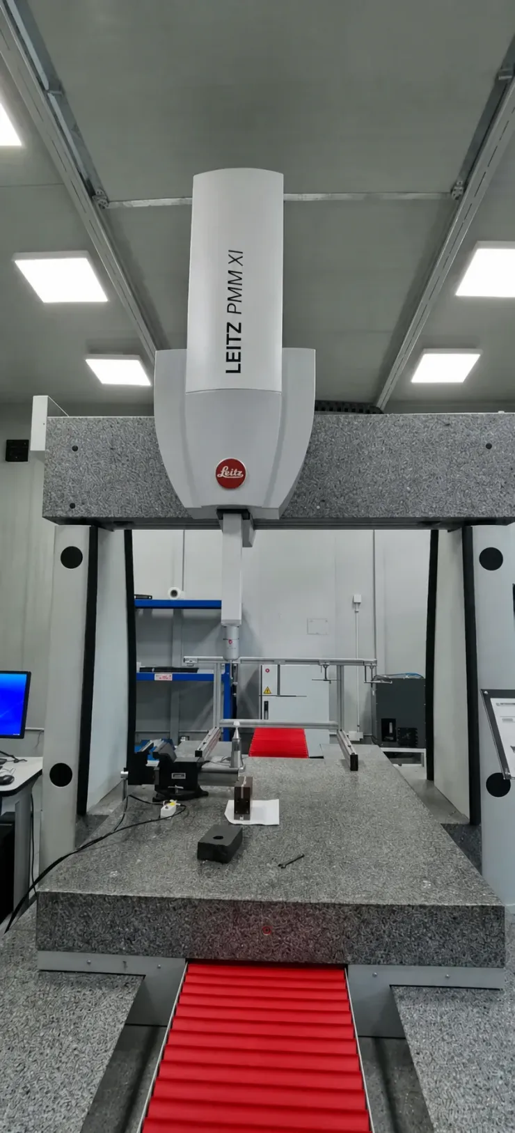
Springback behaves too. The fluid packs the sheet against the cavity at full pressure before release. Complex radii come out inside 0.25 to 0.5 mm on contour with almost no elastic recovery. A matched draw die on the same geometry usually needs a coining stroke. The punch-side physics, draw radius and blank holder force, sit in the deep draw die design guide.
The Single-Sided Die and Tool Set
The hydroforming die is a female cavity block plus a sealing band around its perimeter. High-pressure ports feed the fluid chamber behind or above the blank. There is no punch block and no matched die half grinding into the cavity. One parting plane, one cavity, one seal system, and a base plate carrying the assembly to the press bed.
Die steels follow the forming pressure and the volume. P20 at 28 to 34 HRC carries prototype and low-volume cavities, machined and etched with no heat treat wait. Production cavities run H13 or 1.2344 tool steel. Hardness lands at 48 to 54 HRC. That band takes 150 MPa pad loads and pressure pulses without peening or heat checking. Small inserts can go to the HRC 62 ceiling we hold when abrasion drives the choice. The grade spread is set out in the P20 vs H13 vs S136 comparison.
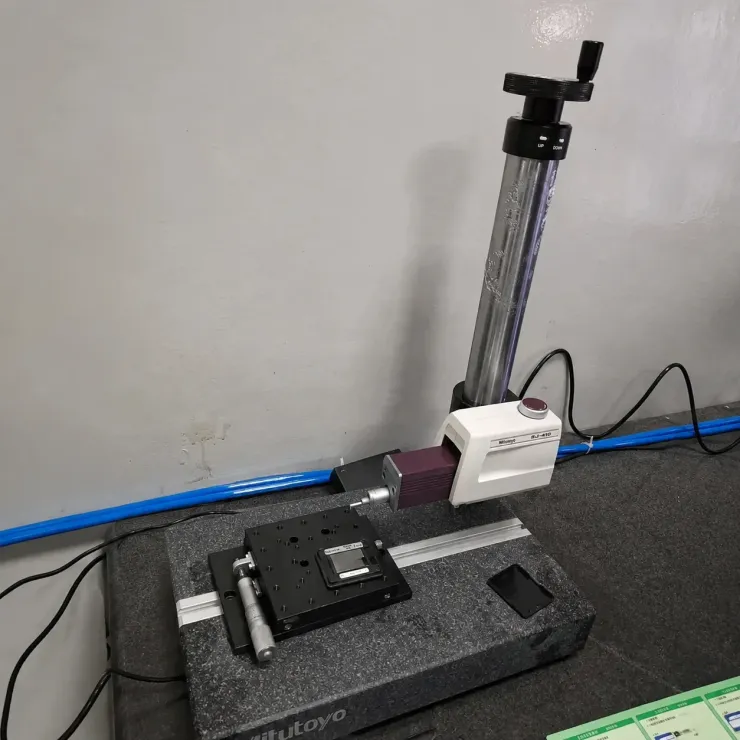
Surface finish is not decoration here. The sheet mirrors the die face, so a cosmetic part needs the cavity polished to Ra 0.4 micrometre or better. Any scratch, weld repair or EDM re-cast layer prints straight onto the panel. Corner radii a mill cannot reach go to wire or sinker EDM. We hold those to plus or minus 0.005 mm, with plus or minus 0.002 mm on EDM and jig grinding.
The economics sit in the single face. One cavity block, one seal band and a base plate land at 15,000 to 60,000 USD for most sheet parts. A matched draw die set for the same part runs 40,000 to 150,000 USD. Tool lead time runs 2 to 5 weeks under an IATF 16949 quality system. Standard parts such as seal rings, ports and fasteners ship in 3 to 7 days.
Steel Pad versus Rubber Membrane
Two machines deliver the pressure, and the die must match one of them. A steel-pad hydroforming press clamps a flat or dome-shaped rigid plate onto the blank and pressurizes the chamber behind it. The plate barely deflects, pressure goes high, and the fluid takes the shape. A membrane press stretches a rubber or polyurethane diaphragm over the cavity, and the diaphragm seals against the blank as it descends.
The steel pad wins on life and pressure. A hardened pad plate runs for hundreds of thousands of cycles with only resurfacing, reaches the full 150 MPa band, and transfers almost no heat into the blank. Its weakness is the sealed edge: the pad meets the die at a parting line that must close on the blank with a metal-to-metal seal, which demands tight flange geometry and a disciplined trim.
The membrane wins on the seal and on deep corners. A rubber diaphragm wraps the part and seals itself, so sharp cavity details down to 1 mm radii fill without an edge leak. The cost is consumable life: rubber or polyurethane diaphragms last 2,000 to 20,000 cycles depending on pressure, stretch and part sharpness. At 2,000 cycles a membrane is a changeover item on the schedule, not a tooling decision.
Tube hydroforming uses neither pad as the forming face. Internal fluid pressure plus end-feed rams do the work, and the die is again a split female cavity. The sealing moves to the tube ends, where plug-and-collet assemblies hold 100 to 400 bar against axial force. An end seal that slips at 300 bar stops the press for minutes per part, so the collet hardware belongs in the maintenance plan next to the cavity.
Decide pad or membrane before the cavity is cut. The seal band, the vent layout and the flange width all change with the machine. A cavity built for a membrane will leak at the flange on a steel-pad press. A steel-pad flange seal wastes the edge-wrap advantage a membrane offers.
Seal Design Decides Uptime
More hydroforming downtime comes from seals than from cavities. A polyurethane or urethane seal is rated to 80 to 150 MPa, and that rating assumes the gap beside it stays under 0.10 mm at full pressure. Metal deflects, the pad tips a few hundredths, and once the extrusion gap opens the seal flows into it, nicks, and leaks at 60 MPa on what should have run at 120.
Size the groove to the seal, not to the space left over. A working rule set: groove 2 to 3 mm wide and 1.5 to 2 mm deep for a 1.5 to 2 mm seal cord, giving 20 to 30 percent squeeze. Keep clearance from groove edge to pad face at 0.2 to 0.3 mm, and back the seal with a harder anti-extrusion element whenever pressure passes 80 MPa.
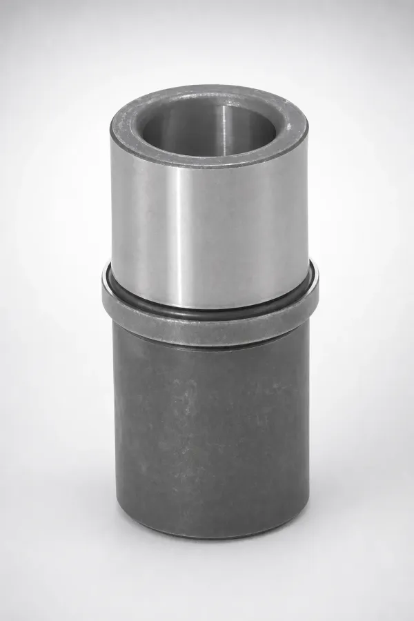
Flat seals and radial seals solve different problems. A flat seal loads the blank edge against the die face and is simple, but it runs the full perimeter of the part where the flange must be flat and trimmed to plus or minus 0.2 mm. A radial seal sits in a bore around the cavity wall, self-energizes as pressure climbs, and tolerates a rougher flange, but the groove is harder to machine and every corner is a leak candidate.
Write the seal into the die drawing as a wear item. Grooves that allow a ring replacement in 15 to 30 minutes, with the seal out of the pressure path and reachable without lifting the pad, turn a leak into a planned stop. Grooves cast into a monolithic cavity turn the same leak into a tool that goes out of service.
Blank and Preform Discipline
Pressure cannot rescue an out-of-size blank. Sheet hydroforming needs the blank to plus or minus 0.2 mm on outline, and corners need trim relief so the metal feeds instead of stacking. A square corner with no relief gathers into a fold, the fold prints into the membrane or pads against the steel face, and the part comes out with a crease no pressure profile removes.
Lubrication has to survive the contact. Drawing compound rated for punch work washes out at 100 MPa of fluid contact, so the film must carry through graphite or PTFE layers rated for that pressure band. On stainless, a film that breaks at one corner galls onto the polished cavity and the next 50 parts copy the pick-up. Re-verify lubricant coverage against the cavity finish every 500 to 1,000 cycles on a cosmetic program.
Tube work adds a preform station. Tubes are bent, and often bulged or flow-hole pre-pierced, before entering the high-pressure die, because a straight tube will not wrap a 300 mm roll bar radius without folding. Check the preform against the burst die on a CMM, since a 1 mm drift in a bend angle changes wall distribution inside the cavity and moves thinning toward the burst limit.
Grain and lot behavior matter more than in press drawing. Fluid pressure loads every square centimetre, so a blank with uneven hardness or an off-direction grain forms a matched pair differently. Incoming checks on hardness spread and coating thickness, both kept inside a 10 percent band across a lot, stop a cavity chasing part-to-part drift that the die cannot fix.
Venting and Water Management
Air trapped between blank and cavity reads as a filled-short corner. The last-fill point, usually a deep radius or a boss, needs a vent path to atmosphere or to the low-pressure side. A working band is 0.3 to 0.5 mm vent depth at that point, land-length guarded so the sheet does not extrude into it. Vacuum-assisted cavities pull 20 to 60 kPa below atmosphere ahead of the blank and remove most of the trap, at the cost of a sealed die perimeter.
On tube dies the trap moves with the fluid. Fill lines must sweep so no high point holds gas, because a gas pocket at 300 bar compresses, heats and detonates a wall locally. Drain and refill lines are sized so the chamber empties in seconds, not the 10 to 30 seconds a part budget cannot carry.
The hydraulic system protects itself with filtration. Fluid returning from the die carries membrane particles, seal crumbs and trim slivers, so a hydroforming loop is held at NAS 9 cleanliness or better. One scored cylinder later, at the cost of a teardown plus a plugging of the die ports, is the usual reason shops tighten the filter spec rather than the other way around.
Water-based forming fluids on sheet cells need corrosion control in the die too. An H13 cavity at 50 HRC still rusts overnight, so a water loop carries a rust inhibitor at supplier dosage, and the die gets oiled and covered between shifts. A cavity that shows flash rust at Ra 0.4 prints it into the first 200 parts before anyone notices.
Cycle Economics and the Volume Window
A hydroforming cycle runs 60 to 300 seconds per part. The pressure ramp, dwell, drain and clamp sequence cannot match the 5 to 15 seconds of a progressive press. The process earns its place where tooling savings and part quality outweigh that speed gap. The comfortable window sits at 500 to 20,000 parts per year, where one cavity die at 15,000 to 60,000 USD beats a three-station draw line at 40,000 to 150,000 USD before anyone counts anneal furnaces or coining presses.
Material loves the band too. 1 to 3 mm aluminum and stainless draw cleanly under fluid pressure, at 20 to 150 MPa, without the galling those alloys cause on a steel punch. Stainless sink bowls and appliance fronts are the classic sheet jobs. High-strength tube for roll bars at 100 to 400 bar replaces welded assemblies, and one hydroformed manifold deletes six stamped weldments plus their fixture.
Count the secondary savings when you compare cycles. The hydroformed part arrives with nearly no springback, contour inside 0.25 to 0.5 mm, and a wrinkle-free cosmetic face straight off the die. The draw route buys speed and pays for it with a trim die, a coining stroke or hand finishing, plus a punch regrind schedule. Neither answer is universal. A 10-million-part bracket is stamping's. A 5,000-part EV tray with a 60 mm depth is hydroforming's.
Budget the consumables honestly into the per-part cost. A membrane at 2,000 to 20,000 cycle life and a set of edge seals every 1,000 to 5,000 cycles are not tooling failures. They are scheduled purchases, and a plant that stocks them runs the cell at planned uptime. A plant that does not loses 4 to 8 press hours per leak. The quote-side framing, where die money actually goes, is in the stamping die budget guide.
Hydroforming versus Deep Drawing
The decision between the two routes is a table decision, not a taste decision. Depth, volume, cosmetic face and springback pick the process, and the die follows.
| Factor | Hydroforming die | Matched draw die set |
|---|---|---|
| Draw per station | 2.0 to 2.6 draw ratio in one pull | 1.8 to 2.1, multi-stage above that |
| Tooling count | One cavity plus pad or membrane | Punch, die, blank holder, trim per stage |
| Tool cost | 15,000 to 60,000 USD per cavity | 40,000 to 150,000 USD per set |
| Cycle time | 60 to 300 seconds | 5 to 15 seconds in press lines |
| Springback | Nearly gone, 0.25 to 0.5 mm contour | Compensation cuts or coining stroke |
| Failure mode | Burst above 10 to 15 percent thinning | Wrinkle, tear at the die radius |
← swipe to scroll →
Table note: cost, ratio and cycle bands are typical industry values. Confirm them against your press datasheet, the alloy's forming limit curve and your volume plan before choosing the route.
Common Hydroforming Die Failures
Hydroforming defects repeat, and each one carries a number that points at the cause. A burst corner, a filled-short deep end, a leak-down and a copied cavity scratch on the cosmetic face trace back to four tooling decisions: radius, vent, gap, blank.
| Failure | Root cause in the tool | Number to check |
|---|---|---|
| Corner burst | Radius too tight, wall thins past burst | Keep radius at 1.5 x thickness, thinning under 15 percent |
| Filled-short deep end | Trapped air at the last-fill point | Vent 0.3 to 0.5 mm or vacuum 20 to 60 kPa pre-pull |
| Pressure cannot build | Seal extruded into an open gap | Gap under 0.10 mm, groove 2 to 3 by 1.5 to 2 mm |
| Fold line on flange | Blank oversized or corners unrelieved | Blank plus or minus 0.2 mm with corner relief cuts |
| Surface copy defect | Cavity scratch or re-cast printing through | Polish to Ra 0.4 micrometre, EDM re-cast removed |
| Scored actuator | Die debris returned to the loop | Filtration at NAS 9 or cleaner |
← swipe to scroll →
Table note: thresholds are working bands for sheet hydroforming on aluminum and stainless. Verify the seal rating and pressure limits against the seal supplier sheet for your specific compound.
Two rows are the same mistake seen from different sides. A burst corner and a fold line both start with the blank, one from too little feed metal at a radius and one from too much at a corner. Measure the blank before you touch the cavity, because a hydroforming die cannot compensate for outline error the way a punch-and-die clearance can absorb a little drift.
Hydroforming Die Design Checklist
Run this list against the tool drawing before the cavity block goes to the shop floor. Each line is a number a reviewer can read off the print.
- Pressure plan. Forming band written down: 20 to 150 MPa for sheet, 100 to 400 bar with axial feed for tube, matched to the pad or membrane route.
- Steel and hardness. P20 for low volume, H13 or 1.2344 at 48 to 54 HRC for production, inserts to HRC 62 where wear demands it.
- Cavity finish. Ra 0.4 micrometre on cosmetic faces, EDM re-cast stripped, radii at 1.5 x sheet thickness minimum.
- Seal system. Groove 2 to 3 mm wide, 1.5 to 2 mm deep, clearance to pad 0.2 to 0.3 mm, extrusion gap under 0.10 mm, replaceable seal ring.
- Vent map. 0.3 to 0.5 mm at every last-fill point, or a vacuum pre-pull at 20 to 60 kPa, with drain time under 10 seconds.
- Blank spec on the print. Plus or minus 0.2 mm outline with corner relief, lubricant rated past 100 MPa contact.
- Fluid loop. Filtration at NAS 9 or cleaner, inhibitor dosing on water loops, ports sized for the ramp rate.
- Acceptance evidence. CMM report inside plus or minus 0.005 mm on the cavity, a trial part with thinning under 10 to 15 percent, contour held at 0.25 to 0.5 mm.
The Bottom Line
Hydroforming die design lives on a short numeric spine. Pressure at 20 to 150 MPa on sheet and 100 to 400 bar on tube buys draw ratios of 2.0 to 2.6, thinning held under 15 percent, and springback near zero at 0.25 to 0.5 mm on contour. The tool is one cavity face, P20 or H13 at 48 to 54 HRC, polished to Ra 0.4 where the part is seen, at 15,000 to 60,000 USD against 40,000 to 150,000 USD for a matched set.
The uptime sits on the seal. Keep the extrusion gap under 0.10 mm, the groove at 2 to 3 by 1.5 to 2 mm, the vents at 0.3 to 0.5 mm on the last-fill corner, and the fluid at NAS 9. The volume window sits at 500 to 20,000 parts on 1 to 3 mm aluminum or stainless, where a 60 to 300 second cycle still wins on total cost.
DieStrike designs and cuts the single-sided cavity die under an IATF 16949 quality system, to plus or minus 0.005 mm with plus or minus 0.002 mm control on EDM and jig grinding, across 120+ machines. Standard components ship in 3 to 7 days and tool lead time runs 2 to 5 weeks, with tier-1 references including TE, Amphenol, Luxshare and Dongshan. Send the part print and the pressure plan through stamping die manufacturing, and the cavity arrives with the seal band already designed in.
KEEP READING
Related Reading
How to Design Deep Draw Dies
Draw ratio, blank holder force and punch radii for matched deep draw die sets, the process hydroforming replaces.
Read articleArticleP20 vs H13 vs S136 Mold Steel
Hardness, toughness and polish behavior of the three die steels that carry most hydroforming cavity blocks.
Read articleArticleHow to Budget a Stamping Die
Where die set money goes: steel, machining, heat treat and the lead time lines on a forming tool quote.
Read articleServiceStamping Die Manufacturing
IATF 16949 cavity dies for hydroforming and deep draw work, cut to plus or minus 0.005 mm in 2 to 5 weeks.
Read articleNEXT STEP
Ready to Start Your Mold?
Send us your element dimensions or part numbers — our team responds within 24 hours. Pricing and lead time come with the answer.

Written by
Ray ChanExport Brand Manager at DieStrike. Ray helps global importers, distributors and OEMs source factory-direct molds and mold parts.