
How to Design Large Injection Molds: Plates, Support and Handling
Table of Contents
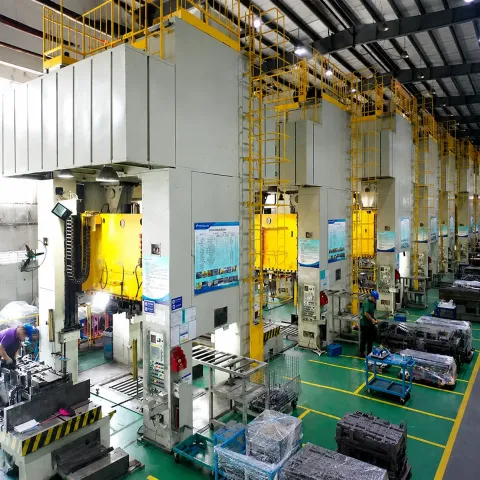
A 1,400 mm by 1,100 mm housing tool went into production on a 380 mm cavity plate with no support pillars under the pocket. After 40,000 shots the parting line had bowed 0.28 mm at the centre, the flash band measured 0.4 mm across three faces, and the tool came off the press for a support grid to be cut into the base plate. That repair consumed eleven production days and about USD 14,000 on a tool that was otherwise built to drawing.
This guide covers the structural side of large tool design above roughly 1,000 mm and 2 t: clamp and separating force, plate thickness, deflection and support pillars, alignment hardware, the machine interface, melt delivery, cooling, ejection, rigging and maintenance access.
The Snapshot
- Separating force of 43,200 kN. A part with a projected area of 1,200 by 900 mm at 40 MPa of cavity pressure pushes 43,200 kN against the clamp, so the press class and the support layout set the limit rather than the cavity detail.
- Parting-line deflection under 0.05 mm. A 1,200 mm unsupported span needs 180 to 250 mm of plate steel, or support pillars every 250 to 350 mm under the pocket floor.
- Four to six guide pin sets of 50 to 80 mm. A 0.05 mm misalignment over a 1,500 mm face is a flash channel, and side locks plus a taper lock take the shear that the pins should not carry.
- Cooling at 25 to 40 L/min per circuit and 3 to 8 bar. A 2 m plate should show a 5 to 8 °C rise from inlet to outlet, measured on parallel circuits with individual flow meters.
What Makes Large Molds a Different Problem
Below about 1,000 mm and 2 t, an injection mold is mostly a cavity problem: the plates are thick enough that the frame barely moves. Above that line the tool becomes a structure that happens to contain a cavity. Machine class moves with the tool, since large housing tools run on 800 to 4,000 t presses, tool mass lands between 2 and 20 t, and cavity plates run from 1,000 to 2,500 mm on a side.
The decisive number is separating force, not part size. Cavity pressure acts on the projected area of the part and pushes the two halves apart. A 1,200 by 900 mm part has a projected area of 1.08 square metres, and at 40 MPa that area generates 43,200 kN, which is about 4,400 tonnes of force trying to open the tool.

Pressure at that level is normal on a thick-wall or long-flow part, while a 300 by 200 mm connector at 60 MPa generates only 3,600 kN. The cavity inserts can still hold plus or minus 0.005 mm while the parting line opens 0.3 mm under load, and both statements are true at once.
| Part class | Projected area | Cavity pressure | Separating force | Press class |
|---|---|---|---|---|
| Precision connector, 300 by 200 mm | 0.06 square metres | 60 MPa | 3,600 kN | 150 to 250 t |
| Appliance housing, 800 by 600 mm | 0.48 square metres | 35 MPa | 16,800 kN | 1,800 to 2,200 t |
| Stack mold, two levels of 600 by 500 mm | 0.60 square metres | 35 MPa | 21,000 kN | 2,200 to 2,500 t |
| Large cover, 1,200 by 900 mm | 1.08 square metres | 40 MPa | 43,200 kN | 4,000 t and above |
← swipe to scroll →
Table note: separating force is projected area multiplied by cavity pressure. Confirm the peak with a cavity pressure sensor study rather than the machine setpoint, because gate pressure can run 20 to 40 percent above the shot average.
Plate Thickness and Parting-Line Deflection
Plate thickness is set by deflection, not by cavity depth. A plate that closes flat at room temperature will still bow once cavity pressure arrives, and that bow shows up as flash along the centre of a long edge.
Set the design target at 0.05 mm of parting-line deflection under full cavity pressure. That gap is still a flash path for a low-viscosity melt at 40 MPa, but it is a limit that can be measured and held by a support grid.
Span drives deflection with a fourth power relationship, so halving the unsupported span cuts deflection by roughly sixteen times. That is why pillars buy more than raw plate thickness: a 1,200 mm span needing 180 to 250 mm of steel becomes a 300 mm span once a pillar grid is fitted, and 300 mm is held by 60 to 80 mm of plate.
Backing and support plates above 1,000 mm are commonly cut from 1.2311 or 1.2738 pre-hardened to HRC 28 to 34, because they must stay flat rather than stay hard. Keep the backing plate at least 60 mm thick even where the calculation allows less.
Two checks belong in the review before a block is ordered: a deflection calculation on the largest unsupported span, run with measured cavity pressure rather than the machine gauge, and a flatness check on the assembled stack at 0.02 mm over 1,000 mm.
Support Pillars and Preload
Support pillars carry the separating force from the cavity plate into the support plate and the platen. They take no load until the surfaces touch, so they are fitted proud of the pocket floor and preloaded by a controlled amount.
The working preload runs 0.02 to 0.05 mm proud of the plate face. Below 0.02 mm the plate still deflects by the gap before any load reaches the pillar. Above 0.05 mm the pillar holds the plates apart at the parting line and the tool flashes around it.
Spacing follows the span. On a 1,200 mm plate, pillars every 250 to 350 mm hold the unsupported span at 300 mm or less in both directions, so a grid of three by four pillars covers a 1,200 by 900 mm pocket without crossing the cooling circuit.
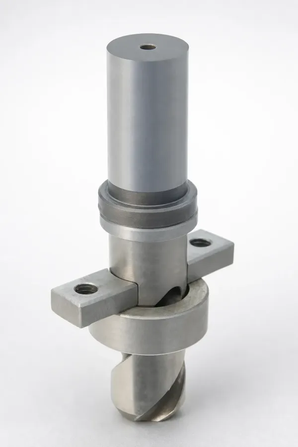
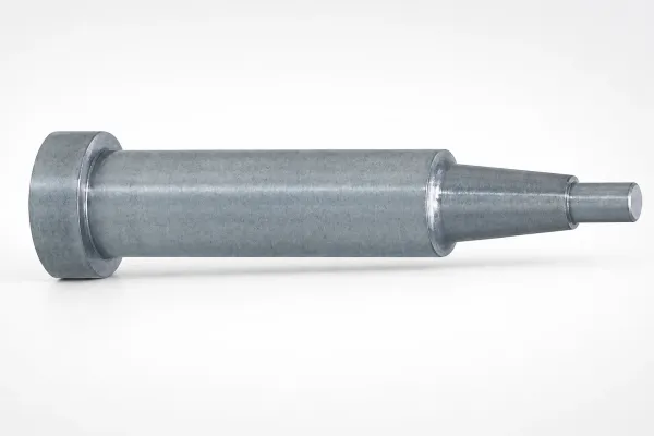
Pillar diameter runs 60 to 100 mm, hardened to HRC 50 to 54, ground flat on both ends and seated on 0.05 mm and 0.10 mm shims so the preload can be adjusted without re-machining. Keep every pillar 20 mm clear of a cooling channel wall, because a pocket that breaks into a water line leaks at 3 to 8 bar.
Verify the preload with bluing at 70 to 80 percent contact on the pillar face, cold and again after the first 500 cycles. Fit pillars in both halves above 2 t, because a 2 t ejector plate that flexes 0.1 mm marks a thin wall across its whole face.
Alignment Hardware for Long Spans
A single guide pin pair that works on a 400 mm tool lets a 1,500 mm plate walk, because the pins sit far from the centre of thermal growth.
Use four to six guide pin sets at 50 to 80 mm diameter above 1,000 mm. Bushes run at HRC 58 to 62 with 0.02 to 0.04 mm clearance on diameter, and pin engagement before the faces meet should reach 1.5 to 2 times the pin diameter.
Thermal growth sets that pattern. Steel expands about 11.5 micrometre per metre per degree C, so a 1,500 mm base running from 20 to 70 °C grows roughly 0.86 mm radially from the centre. Keep the pins symmetric about the centre and never let one corner pair act as a fixed reference, because a corner-referenced tool binds its pins within 20 to 30 minutes of warm-up.

Guide pins are not side-load hardware. Add two to four straight side locks per side at 25 to 40 mm wide with 15 to 25 mm of engagement, plus one taper lock at a 5 to 10 degree angle to take the last 0.5 mm of closure.
Check alignment with the halves closed and warm. A 0.05 mm misalignment over a 1,500 mm face opens the shut-off along its whole length, and bluing at 70 to 80 percent contact is the pass criterion rather than a feeler gauge on a cold tool.
Clamping and the Machine Interface
A large tool is held to the platens by 8 to 16 clamps. Clamps do not resist separating force, because the tie bars carry that load. They resist tool mass, platen acceleration, the opening impulse and the reaction from core pulls and ejector systems.
Size the clamp set so total rated capacity reaches at least twice the tool mass, spread along both long edges. Never clamp only the four corners of a 2,000 mm plate, because the middle lifts under the opening impulse.
Clamp slots run 22 to 32 mm wide at a 150 to 250 mm pitch to match the platen pattern, and the locating ring at 100, 125 or 150 mm must match the platen bore. Match the sprue radius, typically R12 to R20, to the nozzle tip on the machine that will run the tool.
Press architecture changes the design. A two-platen press deflects its moving platen 0.1 to 0.3 mm at full tonnage, so a tool with a thin base plate follows that deflection and opens the centre of the parting line. Add a 60 to 80 mm support plate or move clamp positions toward the edges. A tie-bar-less press often limits tool mass to 3 to 6 t per platen, so a 20 t tool cannot be clamped on one whatever its tonnage rating.
| Interface item | Specification | Failure if wrong |
|---|---|---|
| Locating ring | 100, 125 or 150 mm, matched to the platen bore | Sprue bush off axis, nozzle leak at 2 to 5 MPa |
| Clamp slots | 22 to 32 mm wide at 150 to 250 mm pitch | Tool shifts on the platen by 0.1 to 0.3 mm |
| Clamp capacity | Total at least 2 times tool mass | Tool walks or drops on the opening impulse |
| Platen mass limit | 3 to 6 t tie-bar-less, 10 to 20 t two-platen | Platen deflection, parting-line bow at the centre |
| Sprue radius | R12 to R20 matched to the nozzle tip | Flash at the sprue and a cold slug at every start |
← swipe to scroll →
Table note: interface dimensions must be read off the actual press drawing. Measure the platen bore, the T-slot pitch and the maximum tool mass before the base plate is cut. The tonnage calculation itself follows the method in the clamp tonnage guide.
Melt Delivery Across a Long Flow Path
A 2 m flow path defines a large tool. Melt travelling 2 m along a 2.5 mm wall loses most of its pressure before the far edge, so a single gate either under-packs that edge or forces pressure high enough to bow the plates and flash the tool.
Split the fill with multiple gates or a sequential valve gate system, and hold fill balance within 5 percent across the 2 m flow length. On a 1,200 mm cover that usually means six to twelve drops rather than two, verified by part weight across 30 to 50 shots and a short-shot pattern.
Manifold growth sets the drop positions. A 2,000 mm manifold grows 8 to 12 mm between 20 °C at assembly and 280 °C in production, so it is bolted at one central reference and allowed to slide outward, with drops positioned from cold coordinates plus a calculated expansion allowance.
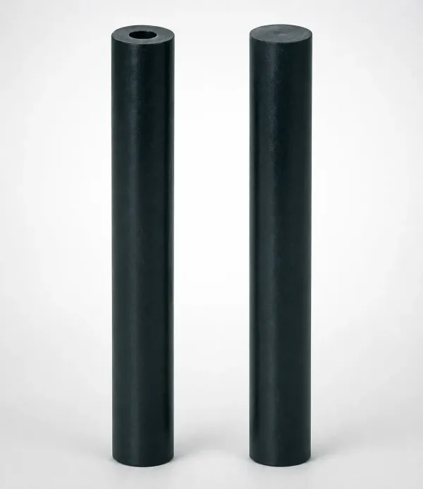
Manifold steel is normally 1.2343 ESR or 1.2344 at HRC 48 to 52, in a plate 60 to 120 mm thick for a twelve-drop system. Runners run 8 to 12 mm and gate diameters 1.5 to 3 mm on a 2.5 mm wall.
Sequential gating also lowers the structural load. Opening drops over a 0.5 to 2 second sequence cuts peak cavity pressure by 20 to 40 percent against a simultaneous fill, and that reduction often decides whether 43,200 kN of separating force fits a 4,000 t press. Thick-wall parts run at the top of that pressure band, as the thick-wall mold guide sets out.
Cooling a Large Cavity Plate
Large plates are cooled with drilled grids, not with conformal channels. A 1,200 by 900 mm cavity plate is served by straight gun-drilled channels of 12 to 16 mm at 20 to 30 mm spacing, 15 to 25 mm below the cavity surface, because a conformal insert rarely covers more than a 300 mm square.
Flow is what makes the grid work. Each circuit carries 25 to 40 L/min at 3 to 8 bar, and a 16 mm channel at 30 L/min moves water at about 2.5 m/s with a Reynolds number near 40,000.
Run circuits in parallel with a flow meter on each one, not in a single long series loop. A series loop longer than 1.5 m picks up 5 to 8 °C across a 2 m plate, and that gradient becomes uneven shrinkage and a warped part, so use four to eight parallel circuits per half.
Every circuit needs a plug that can be pulled for cleaning without lifting the plate, because scale narrows a 16 mm channel to an effective 10 mm over 500,000 shots. DieStrike drills and manifolds these grids in house, with flow meters and temperature ports fitted before the tool reaches the trial press, and the same layout is reviewed during the injection mold manufacturing DFM stage.
Ejection of Large-Area Parts
A 1,200 by 900 mm part can leave 20 to 60 kN of release force on the core after the mold opens, and on a tool of this size the ejector plate itself weighs 300 to 2,000 kg.
Guide every large ejector plate on four to six pins of 30 to 50 mm diameter in hardened bushes, and seat it on a support plate when it retracts. A 2 t plate that sags even 0.1 mm marks a thin wall across its whole face.
Fit four to eight return springs sized to return the plate against residual grip and plate friction, compressed to 25 to 35 percent of free length at full stroke. Springs run past that range lose load within 100,000 cycles.
Use area, not point force, on big thin walls. A stripper plate pushing on the full perimeter is the first choice for covers and housings, and air assist through the core at 0.4 to 0.6 MPa for 1 to 3 seconds breaks the vacuum before the ejector moves.
Ejector systems on stack tools carry double the part load, because both levels move on the same stroke, and the extra support they need is covered in the stack mold design guide.
Handling, Rigging and Transport
A 2 to 20 t tool moves at least four times in its life: to the trial press, back for correction, to the customer and between presses. Each move is a lift that needs hardware rated for the load.
Size eye bolts so a single bolt is rated for 2.5 times the share of mass it carries, which covers the de-rating that comes with a sling angle away from vertical. Use a four-point lift with an included sling angle of 60 to 90 degrees, because a two-point lift at 45 degrees can lose 30 to 50 percent of the rated capacity in the set.
Plan the crane and forklift path before the tool is built. A 20 t tool needs a lift rated 25 to 32 t, a travel width of 3.5 to 4 m and a floor that takes the point load, with fork pockets 150 to 200 mm wide and 80 to 100 mm high positioned so the tool balances on the truck.
Transport bolts hold the halves closed in transit. Fit four to eight M20 to M30 bolts through the clamp plates and torque them to the plate material, because a 12 t half that separates 20 mm on a truck can crack a shut-off land. Ship on a shipping frame or flat rack that keeps the locating ring and the sprue face clear of the deck.
Store the tool closed and 100 to 150 mm off the floor, with rust preventive on the cavity faces and a tool file that records the last shot count, the wear plate readings and the date of the last vent clean.
Maintenance Access and Wear Control
Large tools wear where they touch. A housing tool running 500,000 to 1,000,000 shots will peen its parting-line lands and close its vents unless those features are replaceable.
Fit wear plates at the parting line and at every sliding contact, hardened to HRC 58 to 62 and 6 to 10 mm thick, bolted rather than welded so they can be changed with the tool on the press. Four to eight plates per side on a 1,200 mm tool is a normal arrangement.
Use replaceable corner inserts on the cavity and core plates, because corners peen first and are the hardest area to re-machine. Leave 0.5 to 1 mm of wear allowance so a worn corner can be re-ground twice before replacement.
Specify a bolt pattern that survives 100,000 cycles and beyond: M16 to M24 bolts on a 150 to 200 mm pitch, grade 12.9, re-checked at 500 cycles and then every 5,000 cycles. Every bolt on the moving half needs clear socket access.
Budget the wear rather than reacting to it. Vents cleaned every 5,000 to 20,000 shots, wear plates measured at 100,000 shots and replaced after 0.05 mm of loss, cavity polish refreshed at 200,000 shots and a full teardown at 500,000. Textured appliance tools carry the extra cost of restoring a grain, which the home appliance mold guide covers.
Large Injection Mold Design FAQ
Q1. When does an injection mold count as a large mold?
When the structural design starts to govern the tool. In practice that means a cavity plate above roughly 1,000 mm, a tool mass above 2 t and a press class of 800 t or more. Below that line the frame is stiff enough by habit, and above it every plate thickness and support position needs a calculation.
Q2. How thick should a large cavity plate be?
A 1,200 mm unsupported span at 40 MPa of cavity pressure needs 180 to 250 mm of plate steel to hold parting-line deflection under 0.05 mm. A thinner plate of 60 to 80 mm works if a support pillar grid every 250 to 350 mm cuts the unsupported span to about 300 mm, because deflection scales with the fourth power of span.
Q3. Why do large molds need support pillars with a preload?
Pillars carry the separating force into the support plate, but only after contact. Set them 0.02 to 0.05 mm proud of the pocket floor. Below that range the cavity plate deflects through the gap first, and above it the pillar holds the plates apart and the tool flashes around the pillar position. Confirm contact with bluing at 70 to 80 percent of the face.
Q4. How many guide pins, side locks and clamps does a large tool need?
Four to six guide pin sets at 50 to 80 mm diameter, two to four side locks per side plus one taper lock, and 8 to 16 clamps with a total rated capacity of at least twice the tool mass. A 0.05 mm misalignment over a 1,500 mm face flashes, and guide pins alone cannot carry the lateral load of an off-centre gate.
Q5. How much does a large hot runner manifold grow when it heats up?
A 2,000 mm manifold grows 8 to 12 mm between 20 °C at assembly and 280 °C in production. Position the drops from cold coordinates plus an expansion allowance, bolt the manifold at one central reference and let it slide outward. Bolting both ends warps the manifold and the seals leak within a week.
The Bottom Line
Large mold design comes down to four structural numbers. Hold parting-line deflection under 0.05 mm with 180 to 250 mm of plate or a pillar grid every 250 to 350 mm. Use four to six guide pin sets at 50 to 80 mm with side locks, because a 0.05 mm misalignment over a long face flashes. Balance fill within 5 percent across the flow length with a multi-gate or sequential valve gate layout. Keep cooling at 25 to 40 L/min per circuit on parallel loops with a 5 to 8 °C rise across the plate. Rig with eye bolts rated at 2.5 times mass and ship the tool on its own frame. Get those right and the cavity tolerances survive the press, the truck and 500,000 shots.
DieStrike builds large injection molds and precision tooling to IATF 16949, with mold accuracy of plus or minus 0.005 mm, plus or minus 0.002 mm on EDM and jig grinding, cavity heat treatment up to HRC 62 and 120+ machines on site. Standard mold components ship in 3 to 7 days and complete tools run 2 to 5 weeks, with tier-1 references that include TE, Amphenol, Luxshare and Dongshan. DFM feedback on a large tool drawing set returns within 24 hours, including a separating force check, a plate deflection review and a support layout for the class of press you intend to run.
KEEP READING
Related Reading
How to Design Molds for Home Appliances
Housing tools above 800 mm, deep draws, textured A-surfaces and the wear budget over 500,000 shots.
Read articleArticleHow to Design Stack Molds: Balance and Support
Two-level tooling doubles projected area and separating force, so the centre support becomes the whole design.
Read articleArticleHow to Design Molds for Thick-Wall Parts
Long pack times and 40 MPa cavity pressure drive the structural load on the plates and the clamp frame.
Read articleServiceInjection Mold Manufacturing
IATF 16949 tool building to plus or minus 0.005 mm, DFM feedback in 24 hours and 2 to 5 week lead times.
Read articleNEXT STEP
Ready to Start Your Mold?
Send us your element dimensions or part numbers — our team responds within 24 hours with pricing and lead time.

Written by
Ray ChanMold Buyer's Guide Author · Precision Mold Manufacturing Specialist. Ray helps global importers, distributors and OEMs source factory-direct molds and mold parts.