
How to Design Powder Metal Compaction Dies: Punches and Wear
Table of Contents
A carbide die bush on an oil pump gear job was pulled at 120,000 strokes because green parts started sticking on the ejection stroke. The bore had grown 0.06 mm, the retaining case behind it had yielded, and three weeks of sintering capacity went with the schedule while the replacement cut. The root cause was not the carbide. It was a radial hoop load of roughly 300 MPa that the designer had treated as a compaction problem instead of a pressure-vessel problem.
This page covers the conventional uniaxial compaction tool set end to end: die stack anatomy, the radial pressure that sizes the bush, green strength and ejection physics, sinter shrink compensation, stroke-life numbers, and multi-level strategies.
The Snapshot
- 200 to 350 MPa of radial load on the die wall. Powder transmits 30 to 50 percent of the axial pressure sideways, so a 700 MPa iron column loads the bush like a thin-wall vessel, not like a punch.
- Green tensile strength of only 10 to 40 MPa for iron. Ejection puts that weak compact in tension at the lower punch shoulder, which is why draft of 0.5 to 1 degree per side is designed in, not hoped for.
- Linear sinter shrink of 0.5 to 1.5 percent on Fe-Cu-C. Die bores are dimensioned oversize by that factor, and the lot that ignores the shrink chart ships parts 0.3 mm under size after the sintering furnace.
- Stroke life splits by bush material. An uncoated M2 bush earns 50k to 200k strokes on abrasive iron powder, carbide runs 500k to 2M, and PVD on the punch faces multiplies life by 2 to 4.
Where Uniaxial PM Sits Against Machining and MIM
Conventional compaction presses pre-alloyed iron or copper powder in a closed die at 600 to 800 MPa for premixed and prealloyed iron grades, sinters the green part, and ships a net-shape component between 100 g and 2 kg. Connecting rods, oil pump gears, sprockets, crankshaft counterweights and soft magnetic cores all live in this band, with finished mass porosity held to the single-digit percent range that a sizing or infiltrating step closes further.
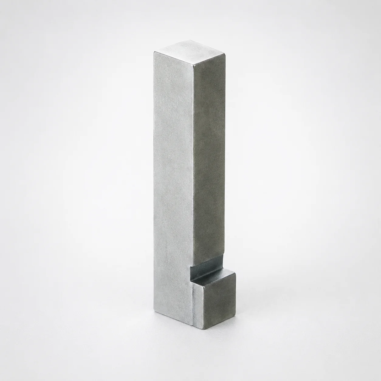
Against machining, a turned and drilled pump gear loses 40 to 60 percent of bar purchase weight as chip, while the pressed gear lands near 97 percent utilization and prints its teeth in one stroke. Against metal injection molding, the honest boundary is mass and detail: MIM owns fine geometry in small parts, and its tool card is on this site in the MIM mold design guide.
Tooling cost draws the boundary harder than physics. A compaction die set lands between 2k and 20k USD, while an MIM mold of the same part family runs 30k to 120k USD. At 10k to 500k parts a year, the PM die set amortizes in weeks and the MIM tool does not. Above roughly 2 kg of iron, or with wall sections over 6 mm, machining and forged bar take the work back.
Press size follows one multiplication: projected green area times pressure times a friction allowance of 1.0 to 1.2, so a 50 cm2 footprint at 700 MPa needs a 300 to 400 ton press.
Die Stack Anatomy and Press Tonnage Math
Read the stack as five separate components, because each one fails differently and each one is quoted separately. The pieces are a die bush, an upper punch, a lower punch, a core rod and a retaining case, and the whole set lives or dies on clearances measured in hundredths of a millimeter.
The die bush is a hardened sleeve whose bore is the negative of the part outside diameter. It guides the lower punch through the fill depth and takes the full radial load during the squeeze. The lower punch defines fill depth from the die-set bottom, rises under the compacting stroke, and then becomes the ejection platform that carries the green part out of the bore.
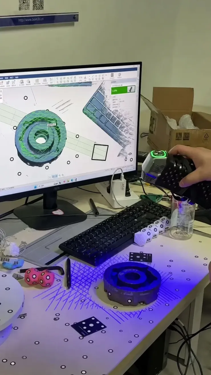
The upper punch closes the cavity, compresses the powder column, and retracts first on ejection because the green part has no strength to release from a face. The core rod forms the through bore; it is typically fixed relative to the die and is the single component that sees compression, tension and abrasion in the same stroke. Punch-to-bush clearance runs 0.01 to 0.025 mm per side, tighter than most stamping habits, because a wider gap leaks powder into a dust line and a narrower gap seizes the moment the bore balloons elastically under load.
Stainless powders compact at 500 to 700 MPa, and binder-heavy warm mixes add a burn-off step at 400 to 600 C before the sinter. The fill column loses 15 to 25 percent of its height under peak pressure, and that densification distance sets part weight, so first-piece acceptance checks weight, not height.
The Radial Pressure Problem
A powder column is not a solid punch path. Under axial load, the granular pack transmits 30 to 50 percent of the pressure sideways against the bore wall, the same Janssen effect that makes a grain silo load its skin instead of its floor. Friction between particles and against the bush is exactly what produces a density gradient down the column, and the same friction is what turns a compaction press into an internal-pressure test on your die.
Run the number for a real bush. An oil pump gear compacted at 700 MPa puts 210 to 350 MPa of radial contact pressure on the bore surface. A solid steel ring with a 40 mm bore and a 70 mm outside diameter sees a tangential stress near its inner wall of 1.3 to 2.2 times that contact pressure by thin-wall Lamé arithmetic, which lands at 400 to 700 MPa hoop stress, above the practical yield margin of most tool steels even after deep hardening. That calculation, not the compaction tonnage, is what decides your material.
This is why a die ID is never monolithic. The standard build is a carbide or high-alloy bush pressed into a hardened steel retaining case with an interference fit of 0.03 to 0.05 mm on diameter, so the case puts the bush wall into compression before the powder ever moves. The prestressed assembly carries hoop loads that would crack a one-piece steel ring of the same size, and when the bush wears, you press out a 300 to 900 USD sleeve instead of scrapping a case that cost ten times that.
Two design traps sit inside this section. First, a bush wall thinner than about 1.0 to 1.5 times the radial depth into the case yields at service pressure and the bore balloons, adding 0.03 to 0.06 mm of growth that reads as oversized parts, then cracks without warning. Second, a press fit driven too hard at assembly adds its own 150 to 250 MPa to the wall stress, and the bush fractures on the press on its first thermal cycle. Chill or heat the case, press true, and record the fit values on the assembly sheet the way an IATF 16949 system expects.
Die Bush Materials: M2 to Cermet
Die bush selection follows annual stroke count and powder abrasivity, not ambition. The ladder starts with M2 high-speed steel at roughly HRC 62 maximum hardness, the sensible default under 100k strokes on prealloyed iron with 0.4 to 0.8 percent integrated wax lubricant. The next rung is powder-metallurgy high-speed steel with a fine, uniform vanadium-carbide structure, typically 3 to 6 times the abrasion resistance of cast M2 and still workable with conventional grinding, a full story on the D2 versus PM tool steel comparison.
Where the volume goes past 200k to 500k strokes, or the mix runs on diffusion-bonded prealloy powder with hard carbide phases, tungsten carbide becomes the default bush. A fine or medium grain cobalt binder grade at ISO K10 to K20 resists the abrasive bore wear that grows a steel bush 0.05 mm in a quarter of its life, and cermet grades with titanium carbide push the corrosion and galling margin on copper-bearing mixes. The price steps land at 1 for M2, 2 to 4 for PM-HSS, and 4 to 10 for carbide on the same bush geometry, with diamond grinding the only machining route on the top rung.
Hardness alone is the wrong dial. A bush with 20 percent coarse carbide in a soft matrix wears faster than a homogeneous PM grade, because pulled-out carbides become third-body abrasives inside the bore. Ask for carbide size and volume fraction on the grade certificate, not just a Rockwell number.
Punches and core rods ride one class below the bush in hardness and one class above it in toughness demand, because they hit a solid reaction face instead of a pre-stressed ring. Standard practice pairs a PM-HSS or carbide bush with through-hardened powder steel punches at HRC 60 to 64, and the geometry rules for those brittle components, ground fits at 0.002 to 0.005 mm, full-length support and no tension paths, are on the carbide component design page.
Green Strength and Ejection Crack Physics
A green iron compact is held together by mechanical interlock and a skin of wax lubricant, not by metal bonding. Tensile strength measures 10 to 40 MPa, compressive strength 60 to 120 MPa, and the gap between the two numbers is the whole failure story. The compact survives 700 MPa of squeeze because every grain sits in compression, and it breaks during ejection because bore friction converts the exit stroke into a tensile pull.
Do the ejection arithmetic before the first stroke. Static bore friction on an unlubricated surface eats 25 to 40 percent of the full compaction load, so a 50 cm2 projected part at 700 MPa can demand 12 to 25 kN just to slide the compact up the wall. That force arrives through the lower punch shoulder, and a shoulder radius under 0.3 mm concentrates it into a line that cracks the bottom face of the part or chips the punch itself. Punch-tip and shoulder radii run 0.3 to 0.5 mm, with the tip edge honed at 0.05 mm rather than left razor sharp.
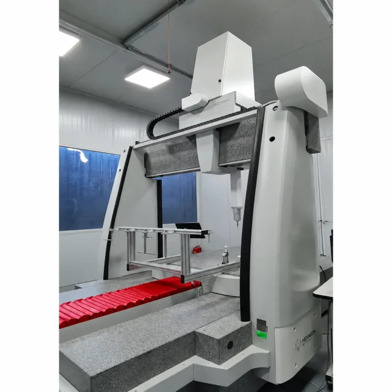
Ejection drafts of 0.5 to 1 degree per side cut that tensile peak by letting the compact contract away from the wall instead of scraping along it, and the same taper is why a die bore is ground with a measured relief angle rather than straight from a solid model. Zero-draft bores show up as laminations: horizontal micro-cracks across a mid-height plane that only open in the sinter, on parts that passed green weight checks for weeks.
Undercuts are forbidden in this process, with no negotiation. A side feature cannot be pulled from a compact with 10 MPa of green tensile strength, so either the feature moves to a collapsible side core that resets on every stroke, or the part gets redesigned with a parting plane that uniaxial motion can make. Copper-infiltrated and steam-treated parts still inherit any crack the design accepted in the green state, which is why a corner crack on a lozenge section is a tooling conversation, not a furnace conversation.
Shrink and Tolerance Compensation Math
The die is dimensioned for a part that does not exist yet. Fe-Cu-C compositions shrink 0.5 to 1.5 percent linearly during sintering, and the direction of the number depends on composition and sintering atmosphere: copper diffusion and grain coalescence pull the part in, while carbon uptake in a dissociating atmosphere can push it toward zero or into slight growth on some mixes. Every die bore is therefore machined oversize by the shrink factor for the specific powder lot, and the shrink chart from the material supplier is a controlled document in the design package, not folklore.
| Dimension stage | Typical tolerance | What sets it |
|---|---|---|
| Green part off the press | +/-0.05 to 0.10 mm | Fill depth repeatability, springback of 0.2 to 0.5 percent |
| As-sintered, 1.0 percent shrink | +/-0.03 to 0.08 mm on a 50 mm feature | Lot shrink scatter of 0.1 to 0.2 percent |
| After sizing or coining at 400 to 600 MPa | +/-0.01 to 0.02 mm | Sizing die closing height, 0.02 to 0.05 mm of recovery |
| Die bore at manufacture | +0.01 to 0.02 mm on the oversize value | Jig grinding at plus or minus 0.002 mm, wear allowance held out |
← swipe to scroll →
Table note: bands typical for prealloyed Fe-Cu-C structural parts between 100 g and 2 kg. Fix the shrink number against a sintered lot from your own powder supplier before cutting a bore, never from a datasheet average.
Green tolerance of plus or minus 0.05 to 0.10 mm collapses or survives depending on the plan. If the drawing calls a sintered dimension to plus or minus 0.02 mm, a secondary sizing or coining die at 400 to 600 MPa recovers 0.02 to 0.05 mm on the critical seats, bore diameters and tooth flanks, and buys that precision with one more station instead of a tighter furnace lottery.
The sizing die is its own tool, and it fails like the compaction bush: radial pressure from a plastic flow with no powder friction to soften it. Sizing punches that bottom at closing height push the full coining load into axial buckling on thin cores, so closing-height controls belong on the sizing layout before the first PMO.
Wear Mechanics and Stroke Life Numbers
Iron powder is a slurry of abrasive. Atomized and water-atomized grades carry hard oxide skins and irregular spikes that polish a bore in the same way honing compound polishes a valve seat, and the wear is concentrated in a band 2 to 4 mm deep at the die mouth where the fill column first touches metal. That band is where your life number is written, and it is why die wear reports measure bore diameter at two depths instead of one.
Baseline life on uncoated tool steel or M2 bushes runs 50k to 200k strokes on prealloyed iron before bore growth reaches 0.03 to 0.06 mm and green parts start sticking on ejection. Carbide bushes push the same wear limit out to 500k to 2M strokes, and that spread, not the unit price, is the reason carbide is the standard answer on a 2 million piece connecting rod program. A PVD coating on the punch faces and core rod, TiN at 2 to 4 micron or TiAlN where the burn-off step runs hot, multiplies punch life by 2 to 4 and suppresses the copper smear that otherwise builds on steel faces.
Bore finish has a threshold and it is tighter than shop comfort. Polish to Ra 0.2 micron or better; a rougher bore picks up powder, drags material along the wall, and raises ejection force by 20 to 40 percent within a few thousand strokes. Wax lubricant at 0.4 to 0.8 percent blended into the mix does the same job from the powder side, and spraying a die wall with a stearate film buys another 10 to 25 percent of ejection headroom on deep, thin-walled parts. Those two numbers, integrated wax plus bore finish, are the cheapest die-life upgrades in the stack.
Track stroke counts the way the wear mode demands. Log the first 50k strokes per 10k interval, then bore-measure at the mouth at 100k on a carbide tool. If bore growth between two checks exceeds 0.01 mm, the coating failed or the powder lot changed, and a lot-to-lot hardness and oxide check on incoming powder is the first call before you blame the tool. Regrind and re-sleeve decisions belong to that trend, not to a calendar.
Multi-Level Compaction Tooling
A flat punch makes a flat part, and most of the tooling money in PM goes into parts that refuse to be flat. A two-level or three-level component, a stepped hub, a flange with a raised boss, needs independently positioned punches so each level reaches its own density target. The tooling consequence is that a double-level part carries a stepped upper punch, a floating lower punch segment, and a core rod that either floats or is pulled, each with its own stop and reset cam on the press.
Density is what you are buying with the extra levels. A single-level compact of a stepped geometry shows 0.4 to 0.8 g/cm3 between its thick and thin zones because friction drops the transmitted pressure along the path, and that gradient becomes a hardness and shrink gradient in the sintered part. Leveling the fill so each section gets its own powder and its own punch travel narrows the spread to 0.1 to 0.2 g/cm3, which is the band a sintered structural part can live in.
The press-side choice is a 1x100 versus 2x100 tool, meaning one cavity per stroke on a high-rate press or two cavities on a slower compacting head. The 2x100 doubles green output per stroke and doubles the punch and bush count, and the decision usually resolves on furnace capacity rather than tooling cost, because a sinter line fed by 3,000 parts per hour is a different layout than one fed by 6,000. A double-level gear blank frequently saves a sizing die: hold the flank profile to plus or minus 0.05 mm in the compact, and the post-sinter sizing station drops out of the routing.
Reset discipline is the hidden design load. Every floating segment must return to its set height within 0.02 mm stroke after stroke, or part weight drifts, and the cam, spring or servo strategy that guarantees reset belongs on the tool drawing. We make the ground punch, bush and core components that ride those cams; the motion itself is a press-builder conversation, and it should happen before your die RFQ goes out.
Four Failures That Show Up Before the First PMO
Copper smear on steel faces. A brass or bronze infiltrated mix, or a copper-bearing prealloy, welds a thin film onto an uncoated steel punch within 10k to 30k strokes. The film changes the bore diameter by 0.02 to 0.05 mm and then sloughs off in flakes that become inclusions. The fix is a cermet or chromium-plated face, or a TiN coating on the punch, not a harder steel, because smear is adhesion rather than abrasion.
Corner cracking on lozenge and rectangular sections. A sharp internal corner on a rectangular compact concentrates the radial pressure release during decompression, and the corner delaminates 0.3 to 1 mm back from the edge. Radius outside corners to 0.5 to 1.0 mm at the design stage and keep punch-tip radii at 0.3 to 0.5 mm; a corner crack that appears only after sintering was still a green-state crack.
Density gradient read as a location failure. Fill-direction flow leaves 0.1 to 0.2 g/cm3 between the entry end and the far end of a long section, and a bend or a press-fit requirement sits right at the low-density end. The symptom is a part that passes weight and fails a bend-radius check. Fix the layout with a fill ramp, a second level or a reversed compacting direction rather than tightening the drawing.
Bore growth misread as shrink drift. A worn or yielded bush adds 0.03 to 0.06 mm to the green diameter, and the same signature appears in parts that shrank 0.1 percent less than the lot chart. Measure the green part, not just the sintered one: growth that is present before the furnace is a die problem, and growth that appears only after is a powder lot problem. That single comparison sorts half of your first-article disputes.
What DieStrike Builds in This Stack
Be precise about where this shop sits in a PM line. We are a die and precision component maker, not a compaction service: no presses, no sintering furnaces, no green parts off our floor. What we build is the wear half of the stack, the bush, punches, core rods and retaining cases that your press supplier closes around.
Capability, stated in the numbers that matter to your drawing: IATF 16949 quality system with PPAP-style lot documentation, 120-plus machines across grinding, EDM and wire work, dimensional control at plus or minus 0.005 mm on mold work and plus or minus 0.002 mm on EDM and jig grinding, through-hardening to HRC 62 maximum, standard components shipping in 3 to 7 days and full tooling at 2 to 5 weeks lead time. Tier-one programs with TE, Amphenol, Luxshare and Dongshan run on that tolerance band, mostly because a core rod at 0.002 mm is the difference between a bore you size and a bore you scrap.
Send the powder grade, the target green density, the annual stroke count and the shrink chart with your RFQ, not just the part model. Those four inputs decide whether your bush is M2, PM-HSS or carbide, and they decide whether the quote is honest. The punch product page lists the standard ground styles, and the contact desk will route a compaction tooling package to the right engineer.
The Bottom Line
A powder metal compaction die is a pressure vessel that also has to eject a fragile part. Axial load is the easy half: multiply the projected green area by 600 to 800 MPa, add a friction allowance of 1.0 to 1.2, and the press tonnage writes itself. The design work lives in the radial load, the 30 to 50 percent of axial pressure that becomes 200 to 350 MPa against the bush wall and, after Lamé amplification, 400 to 700 MPa of hoop stress that decides whether your bush is M2, PM-HSS or carbide inside a prestressed retaining case.
The rest is arithmetic you can do before cutting metal. Dimension the bore oversize by the 0.5 to 1.5 percent lot-specific sinter shrink, hold punch-to-bush clearance at 0.01 to 0.025 mm per side, give the compact 0.5 to 1 degree of ejection draft against a green tensile strength of 10 to 40 MPa, and keep punch-tip radii at 0.3 to 0.5 mm so the ejection load never finds a notch. Choose bush material by stroke count, 100k for steel, 200k to 500k and up for carbide, then protect the punch faces with 2 to 4 micron TiN and a bore polished to Ra 0.2 micron. Fix undercuts by redesign, level the density before you promise a bend spec, and log bore growth at 0.01 mm intervals so the die tells you its own retirement date.
KEEP READING
Related Reading
How to Design Molds for Metal Injection Molding
The injection-side tool card: feedstock flow, shrink rates and cavities for parts too fine for a press die.
Read articleArticleHow to Design Carbide Die Components: Grades, Fit and Failure Modes
Grade maps, 0.002 to 0.005 mm ground fits and the brittleness rules behind a carbide die bush.
Read articleProductPrecision Punches
Punch steels and ground punch components for wear-critical forming and compacting tooling.
Read articleServiceMold and Die Repair, Maintenance
Regrind, re-sleeve and life-review routines for tooling taken out of service at a wear limit.
Read articleNEXT STEP
Ready to Start Your Mold?
Send us your element dimensions or part numbers — our team responds within 24 hours. Pricing and lead time come with the answer.

Written by
Ray ChanExport Brand Manager at DieStrike. Ray helps global importers, distributors and OEMs source factory-direct molds and mold parts.