
How to Design Carbide Die Components: Grades, Fit and Failure Modes
Table of Contents
A progressive die blanking 0.8 mm glass-filled laminate ran 12,000 hits on D2 punches before burr passed 0.15 mm on three stations at once. The regrind cycle collapsed to every 30,000 hits, six punch sets went out for recoating, and the program carried four weeks of unplanned press downtime while the toolshop quoted carbide. The carbide conversion stopped the wear-out. It also started a different failure conversation, because a carbide punch that fails does not wear, it breaks, and it breaks in three predictable places that steel punches never reach.
This page covers carbide component design end to end: grade selection against the sheet, the brittleness rules that decide shank support and corner radii, fit and assembly practice, the clearance shift, the break-even math, and a failure-signature library you can read on the shop floor.
The Snapshot
- Compressive strength of 3 to 5 GPa. Hardened tool steel tops out near 2.5 GPa. Carbide holds usable hot hardness past 600 C, so abrasive and thin stock stops policing your punch life.
- Elastic modulus of 400 to 600 GPa. A carbide punch deflects roughly one-third of a steel punch under the same load, about a 2.3x reduction, and that stiffness is what keeps hole position on 0.1 mm galvanneal stacks.
- Tensile strength of only 250 to 400 MPa. Carbide must never see bending or tension: full-length shank support at a fit no looser than 0.02 mm, 0.4 mm minimum inside corner radius, no cross-holes.
- Clearance of 5 to 8 percent of thickness per side. Steel punches run 8 to 12 percent. Carbide does not wear in gradually, it chips, so the band starts tighter and gets measured, not eyeballed.
- Break-even at 200k to 1M hits. A carbide insert costs 3 to 6 times a steel one and delivers 5 to 20 times the life on GFRP, copper bus bar, battery tab and silicon-steel lamination work.
Why Carbide Wins Against Thin and Abrasive Stock
Tungsten carbide is a composite of WC or TiC grains in a cobalt binder, sintered near 1,400 to 1,500 C into a solid part. Three material facts explain why die makers reach for it on the work that kills tool steel.
The first is compressive strength. Sintered carbide carries 3 to 5 GPa in compression against roughly 2.5 GPa for hardened tool steel at HRC 60 to 62. A blanking edge sits in compression during the shear event, and the carbide edge simply does not deform at pressures that slowly roll and feather a steel edge. On abrasive stock, that resistance to micro-deformation is what stops the edge from widening under the abrasion.

The second is hot hardness. Tool steel starts to give up temper hardness around 500 to 550 C. Carbide holds its hardness past 600 C, which matters in three stamping situations: high-rate blanking of copper and copper-alloy strip, punching of glass-filled and aramid composites where cutting friction heats the edge, and hot-forming adjacent stations. Abrasive work runs hotter than most planners expect, and hot abrasion removes a steel edge several times faster than cold abrasion.
The third is stiffness. Elastic modulus for carbide runs 400 to 600 GPa against about 210 GPa for steel, so a carbide punch of the same geometry deflects roughly one-third as much, about 2.3 times less, under identical load. On a 0.1 mm galvanneal stack running at 300 to 500 strokes per minute, that deflection difference is the reason hole-to-hole position stays inside 0.02 mm instead of wandering. A steel punch bends away from the strip; a carbide punch does not move enough for the strip to notice.
Thin stock magnifies every one of these advantages. Below 1 mm, edge quality controls burr and the wear of a fraction of a micron per 10,000 hits still moves clearance out of tolerance. Silicon-steel lamination stock is the classic case: it is thin, it carries an insulating coating that behaves like fine abrasive paper, and a die set is expected to punch tens of millions of holes before the stack is retired. Carbide is the default there for the same reason it is the default on GFRP and battery tab work.
Grade Selection Map: C-2 to Solid-Lubricant
Carbide grades sort by grain size and cobalt content, and the sorting rule is simple: finer grain buys hardness and edge strength, more cobalt buys toughness and shock resistance. A 1 micron grain at 6 to 10 percent cobalt is a general purpose punching grade. A 0.5 to 0.8 micron fine grain pushes compressive yield and edge wear to the top of the range and is the correct default on thin steel and aluminium foil stock.
Map the common industry C-series letters to the ISO application classes. C-2, roughly ISO K10 to K20, is the workhorse for blanking and piercing mild steel, galvanneal and aluminium at thicknesses from 0.05 to 3 mm. It balances 1 to 3 GPa of transverse rupture strength against wear, and it is the grade to quote when nothing else on the strip argues for a special answer.
C-3, or roughly ISO K30, adds cobalt and toughness for stainless, silicon steel and abrasive non-ferrous work where micro-chipping, not wear, is the failure mode. Punching SUS304 at 0.5 mm or phosphor bronze at 0.2 mm belongs on C-3 or a submicron tough grade, because the sticky, work-hardening materials load the edge unevenly and a harder, more brittle grade will answer with a chipped corner instead of a worn one.

Cored grades put a through-hole along the axis of a round punch to relieve tensile stress in the shank, and they are worth the extra grind cost on long-slender punches over 8 times diameter. Solid-lubricant grades carry dispersed solid lubricant phases that transfer to the cutting edge during punching, and they are the right call on aramid and glass-filled composites. Those materials cut by friction and heat: the resin softens and gums the edge above roughly 150 to 200 C at the shear zone, and a self-lubricating grade suppresses that heat instead of letting the glass filaments saw through the carbide.
Two more branches are worth recognizing on a supplier datasheet. TiC-based cermets trade some toughness for chemical resistance and are used on long-run punching of low-carbon steel without welding buildup. Cemented carbides with 12 to 20 percent cobalt, sometimes called shock-resisting grades, are for intermittent heavy loads such as forming punches, stabs and coins where the edge sees impact rather than shear.
Choose by the strip, not by the price list. The abrasive or sticky material decides grain size; the loading pattern decides cobalt; the shank geometry decides whether the grade needs a core. Everything downstream, from clearance to fit class to expected life, inherits from that one grade decision, so put it on the drawing before anyone grinds a shoe.
Carbide vs PM Steel vs Tool Steel
Carbide is not the only answer to abrasive stock, and buyers regularly over-specify it. The middle rung is powder-metallurgy tool steel: diffusion-bonded or supersintered carbide in a steel matrix, typically 10 to 25 percent vanadium carbide. It carries two to six times the abrasion resistance of D2-class steel, and unlike solid carbide it can be machined, welded and heat treated by a normal toolroom. On the wear-mode ladder it sits between conventionally melted tool steel and solid cemented carbide, and the full steel-side story is in the D2 vs DC53 vs PM comparison.
| Property | Hardened tool steel | PM tool steel | Cemented carbide |
|---|---|---|---|
| Compressive strength | about 2.5 GPa at HRC 60 to 62 | 2.5 to 3 GPa | 3 to 5 GPa |
| Tensile / transverse rupture | 2,000 to 2,500 MPa usable | 1,500 to 2,500 MPa | 250 to 400 MPa |
| Elastic modulus | about 210 GPa | 210 to 230 GPa | 400 to 600 GPa |
| Hot hardness limit | softens past 500 to 550 C | holds to about 600 C | holds past 600 C |
| Typical punch life index | 1x baseline | 2 to 6x on abrasive stock | 5 to 20x on GFRP and lamination |
| Relative insert cost | 1x | 1.5 to 3x | 3 to 6x |
| Toolroom repairability | weld, machine, regrind | weld and machine with care | diamond grind only |
← swipe to scroll →
Table note: ranges are typical published values for punching-grade cemented carbide, PM tool steels and deep-hardened cold work steels. Confirm against the grade certificate from your carbide supplier and the steel datasheet before release.
The decision boundary is hit count and material, not ambition. Under roughly 200k hits on mild or galvanneal steel, hardened D2-class steel at HRC 60 to 62 is the right tool and carbide is dead capital. Between 200k and 1M hits, PM steel usually wins on cost per hit because it can still be repaired in-house. Above 1M hits, or on any glass-filled, aramid, copper or silicon-steel work at any volume, solid carbide earns its premium. On that boundary question, the 12-grade mold steel comparison on this site gives the substrate baselines that the carbide claim is measured against.
Brittleness Rules: Tension Is the Only Way to Break It
Everything that makes carbide a great punching edge also makes it a bad structural member. Transverse rupture strength is only 250 to 400 MPa, an order below its compressive capability, and the material has essentially no plastic zone at the crack tip: a sharp corner under tension either holds or separates. The design rules below are not preferences. Each one exists to keep carbide out of tension and out of bending.
Rule one: support the shank over its full length. The punch shank must ride in a steel guide or shoe with a running fit no looser than 0.02 mm along the entire embedded length. A carbide punch that cantilevers out of its holder by more than about 1.5 times its diameter is a beam under bending load, and beam stresses concentrate at the surface exactly where the tensile strength is lowest. The same stubbiness logic sizes the die button: support the button backing plate so the carbide never spans a void.
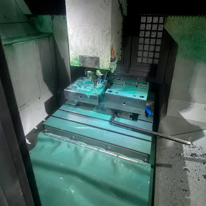
Rule two: keep wall thickness above 2.5 times the load path. Any section that carries the shear reaction should be at least 2.5 times the distance from the cutting edge to the nearest supporting shoulder. Thin carbide webs between adjacent holes are a recurring failure source on multi-cavity form tools; if a web cannot reach 2 mm at the bond between holes, split the punch into two components instead of grinding one.
Rule three: radius every inside corner at 0.4 mm minimum. A sharp inside corner is a stress raiser with a theoretical concentration factor above 3, and carbide is the least notch-tolerant material in the die shop. Grind or hone radii into every internal corner on both the punch and the die button, and never let a drawing dimension a corner as square. Where geometry demands a sharp external feature, put the radius on the mating die instead.
Rule four: avoid through-slots and cross-holes. Any hole or slot through a carbide body interrupts the load path and leaves two half-sections in bending where the material expects compression. Pilot holes, coolant holes and fastener clearance belong in the steel holder, not in the carbide. If a carbide component genuinely needs a slot, spec the slot ends with 1 mm minimum radii and add a 1.5 mm edge margin, then treat that part as a candidate for the shock-resisting cobalt grades in the grade map above.
Fit and Assembly Practice
Carbide is machined one way: diamond grinding, to 0.002 to 0.005 mm on critical fits. There is no milling, no drilling without ultrasonic or EDM assistance, no filing, and no re-working a dimension with a wheel the shop does not have. Order the component to final ground size and build the steel around it, not the other way round. Our own tolerance capability on EDM and jig grinding holds at plus or minus 0.002 mm, which is the same band a carbide grinder works in, so shoe and insert can be matched at assembly instead of adjusted.
Press-fit the carbide into a steel shoe or holder; do not bolt a bare tip together. The standard configurations are a ground cylindrical shank into a ground bore with a light press, a dovetail or T-slot die button seated in a hardened pocket, and a shoulder punch carried in a retaining cap that loads the steel shoulder, never the carbide. The shoe does three jobs: it positions the component, it carries the bending loads the carbide cannot, and it spreads the clamp force over an area that will not crack the insert during assembly.

Torque never goes directly onto carbide. A bolt bearing on a carbide face concentrates a line load at the hole edge, and inserts have cracked during assembly with no stroke of the driver beyond spec. Load through the steel member, use a washer or counterbore that bears on a relieved pocket, and keep clamping pressure under roughly 200 MPa on any carbide contact area.
When a permanent assembly is wanted, braze with silver filler at about 750 C, with a 0.05 to 0.15 mm gap, a nickel flash on the carbide where the supplier recommends it, and a controlled cool-down. Air-cooled brazes shock-crack carbide; furnace or induction brazing with a 50 to 100 C preheat on the steel side is the repeatable route. For anything that will ever be replaced, use a press fit or a mechanical clamp instead, because a brazed joint converts a 200 dollar insert change into a grinding and re-braze project.
Punch Clearance Shifts Down for Carbide
The clearance dial moves the moment carbide enters the station. Steel punches in progressive dies typically start at 8 to 12 percent of stock thickness per side and wear in gradually, so shops set clearance at the middle of the band and regrind when burr appears. Carbide runs 5 to 8 percent per side as a starting point, and here is the reason: carbide does not wear its edge wider over time, it eventually chips. A chipping edge fails suddenly, so the design intent is to reach the shearing zone clean and hold it there, not to nurse a wear-in curve.
Set the number by material rather than by habit. On 0.1 to 0.5 mm galvanneal and tin-free steel, 5 to 6 percent per side keeps the fracture planes close and burr under 0.02 mm for long runs. On stainless and silicon steel, 6 to 8 percent. On GFRP and composites, hold the tighter end of the range, because the glass fibres abrade a widened gap into a taper in less than 100k hits. The full maintenance logic for the steel side, including measurement intervals and regrind triggers, is in punch clearance maintenance in progressive dies; treat the carbide band as a separate column on the same shop chart.
Check the assembly angle, not just the gap. A carbide punch carries a 0.05 to 0.10 mm edge hone at 30 to 45 degrees rather than a razor, and the hone changes effective clearance: a dull-looking edge that is actually honed cuts cleaner and longer than a polished one. When you measure clearance on a carbide station, measure at the honed land, and log the value per station on the die sheet so a 0.01 mm drift shows up as a trend instead of as a chip.
Economics and the Break-Even Hit Count
A carbide insert costs 3 to 6 times an equivalent hardened steel one, and that premium buys 5 to 20 times the life on GFRP, copper bus bar, battery tab and silicon-steel lamination work. The break-even usually lands between 200k and 1M hits. Do the math on the punch that actually dies, not on the die.
Take a concrete shape. A steel punch at 80 dollars wears out at 150k hits on 0.3 mm copper strip, so the punch cost per thousand hits is 0.53 dollars. A carbide punch at 350 dollars reaches 1.5M hits on the same station, or 0.23 dollars per thousand. The carbide wins on unit cost, and it also removes the press stops: each change-out on a 40 station progressive die costs 30 to 60 minutes of lost output, and at 600 hits per minute that hour is worth several hundred dollars of production. Add the change-outs and carbide frequently wins at volumes buyers would never have guessed.
Run the reverse test before you convert. If the program ends at 150k hits, the carbide premium never amortizes and the correct answer is steel with a PM insert on the two fastest-wearing stations. If the strip is mild steel below 1 mm and the run is long, carbide is optional armor rather than a requirement.
The decision sheet is simple: multiply planned hits plus two service lives by the cost per change-out, and compare that against the insert premium. Where the two curves cross is your 200k to 1M window, and it sits closer to 200k on abrasive composites than on galvanneal. The same logic sizes budget conversations on the rest of the tool, which the stamping die budgeting guide on this site covers line by line.

Two hidden line items belong in the comparison. Carbide regrinding needs diamond tooling and takes 2 to 4 times the bench hours of a steel regrind, so set the regrind trigger by burr measurement, not by calendar. And carbide holds scrap value: the cobalt and tungsten in worn inserts carry a genuine recovery price, which a steel punch never offers, so ask your supplier whether they buy back used tooling before you write off the consumables budget.
Failure Signature Library
Carbide components fail in three recognizable signatures, and each one points back to a specific design or assembly error. Read the break before you replace the part, because the fragment itself tells you what to change on the drawing.
Chipping at the cutting edge radius. Small flakes, 0.1 to 0.5 mm, walking along the edge land. This is tensile overload at the edge, and the causes rank in this order: clearance set too tight for the material, strip misalignment feeding into the punch at an angle, or a worn die button that raised effective clearance locally so the punch now hits a partially fractured web. Check pilots and alignment first, then re-measure clearance per station against the 5 to 8 percent band. Edge chipping that appears within the first 10k hits is almost always a fit or alignment problem, not a grade problem.
Catastrophic mid-shank fracture. The punch separates into two or more pieces along the shank, frequently at a grind line or the shoulder radius. This is clamping stress or missing support: the shank was cantilevered beyond 1.5 diameters, the holder bore ran loose past 0.02 mm so the punch flexed in the press, or a retaining cap loaded the carbide directly instead of the steel shoulder. Inspect the holder bore before ordering the replacement; a scored or bell-mouthed bore will break the next insert in the same place.
Abrasive polishing wear on the flank. A mirror-finish band worn into the flat face below the edge, with the punch dimension shrinking 0.01 to 0.03 mm per 500k hits on glass-filled stock. Carbide resists this far better than steel, so visible flank polish means the wrong grade was selected, typically a general purpose C-2 on work that needed a finer grain or a TiC-bearing grade. Move one class harder on the next order and verify the coating abrasiveness of the incoming strip, which varies lot to lot on galvanneal.
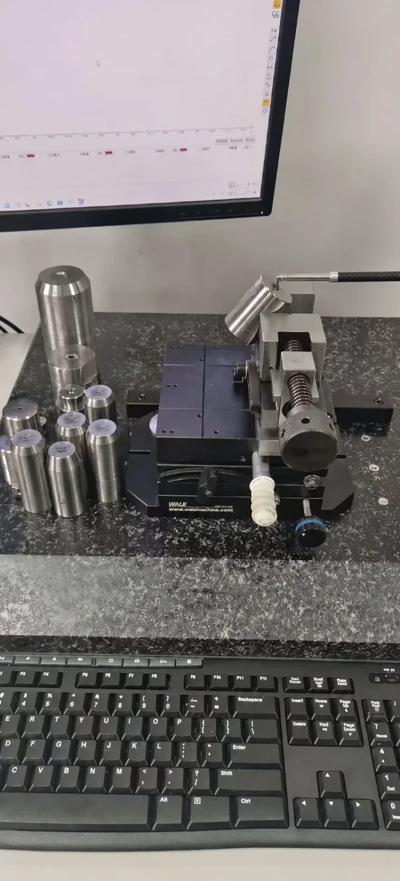
A fourth, rarer signature is binder-phase leaching: a pitted, chalky surface on punches running in wet or chemically aggressive lubricant above 80 C, where the cobalt matrix dissolves and leaves unsupported carbide grains that pop out. Change the lubricant chemistry or switch to a corrosion-resistant grade with added chromium or vanadium carbide in the binder. If the failure pattern on your floor reads differently from these five, the most useful step is comparing shank styles in ball-lock versus shoulder punches, because a loose-fitting shank style can produce carbide symptoms on a steel punch and hide the real cause.
How to Spec a Carbide Component on an RFQ
A carbide RFQ that omits any of the six fields below comes back as a generic grade and a square corner, which is the two-step recipe for the failure library above. Send this list, in this order, and treat any supplier who answers all six without asking as the one to keep.
One: grade and standard. State the C-series letter or ISO class, the grain size band, and the cobalt content if the application is shock loading: for example "submicron grain, 8 percent Co, ISO K20 equivalent, certificate per lot." Two: edge preparation. Specify the hone as 0.05 to 0.10 mm at 30 to 45 degrees on every cutting edge, and say whether the die button edges carry the same hone. Three: fit class. Give the bore or pocket dimension with its tolerance band and the intended assembly method, press fit or braze, so the grinder sizes to the steel, not to the nominal print.
Four: drawing datum. Dimension from the seating shoulder or the pilot diameter, not from the cutting edge, because the edge gets reground during service and every downstream measurement inherits that drift. Five: size after any plating or coating. If the component is plated for corrosion resistance or coated for lubricity, state the required hole and shank sizes after coating, since a plating build-up of 0.01 to 0.02 mm per side changes a 0.005 mm fit into a loose one.
Six: verification. Ask for the ground-size inspection report per part, and for the transverse rupture value on the lot certificate rather than the nominal grade spec.
Carbide lead times run with the same shape as standard die components: 3 to 7 days for stocked shank styles, longer for custom geometries that need fixture setup. For the steel side of the same decision, our punch product page lists the standard sizes and the grinding capability behind them. When a carbide station lives inside a larger tool, the holder steel gets the same verification discipline as any die block, and stamping die manufacturing covers how inserts, shoes and the die set come in through trial.
Design Rule Checklist Before You Release the Drawing
Run every carbide component through this gate before release. Each line traces back to a section above, so the checklist doubles as the audit trail for a supplier review.
- Grade matched to the strip. C-2 or K10 to K20 for steel and aluminium; C-3 or K30 for stainless and abrasive non-ferrous; solid-lubricant or cored grades for aramid and glass-filled composites.
- No tension path. Every section verified in compression under peak load, with shank support over the full length at a fit no looser than 0.02 mm.
- Wall above 2.5 times the load path. Web and land thickness measured on the drawing, not estimated from the model.
- Inside corners at 0.4 mm radius minimum. Punch and die button both, with no square corner dimensioned anywhere.
- No through-slots or cross-holes in the carbide. Pilots, coolant and fasteners live in the steel holder.
- Clearance 5 to 8 percent per side, logged per station. Measured at the honed land, trended on the die sheet.
- Assembly loads steel, never carbide. Press fit or clamped shoulder, no torque on a carbide face, braze only where the part is permanent.
- Break-even above planned hits. The insert premium amortized against change-out cost before the order, not after the first failure.
Two companion decisions sit just outside the carbide scope but belong on the same review sheet: the station's role inside the progressive die layout, since a carbide punch cannot compensate for a strip that walks into the die at an angle, and the edge-quality ceiling of the process itself, where a fine blanking versus conventional stamping decision changes whether you need a carbide edge at all.
The Bottom Line
Carbide is a compressive material wearing a punch's clothes. It gives you 3 to 5 GPa of compressive strength, hot hardness past 600 C, and enough stiffness to cut deflection by roughly 2.3 times, which is why it holds hole position on 0.1 mm stacks and shrugs off glass-filled laminates. It asks for exactly one thing in return: never let it see tension. Support the shank over its full length at a fit no looser than 0.02 mm, keep walls above 2.5 times the load path, radius every inside corner at 0.4 mm, grind fits to 0.002 to 0.005 mm, press-fit into steel, run 5 to 8 percent clearance, and order the grade against the strip rather than the price list.
Do the hit-count math before you convert anything: 3 to 6 times the insert cost buys 5 to 20 times the life, and the crossing point usually lands between 200k and 1M hits. Below that, hardened steel or PM tool steel is the honest answer. Above it, or on any abrasive composite, carbide with a honed edge and a written spec sheet is the cheapest punch you will ever change. When a failure does arrive, read the signature first: edge chips point to clearance or alignment, mid-shank fractures point to support or clamping, flank polish points to grade. Fix the drawing, not just the part.
KEEP READING
Related Reading
D2 vs DC53 vs PM Tool Steel: Wear, Toughness and Cost
The powder-metal rung between tool steel and carbide, and when diffusion-bonded carbide competes on price.
Read articleArticle12 Mold Steel Grades Compared
Hardened tool steel baselines: compressive strength, hot hardness and wear resistance grade by grade.
Read articleArticleHow to Maintain Punch Clearance in Progressive Dies
Clearance bands and regrind intervals for steel punches, and how a carbide edge changes both.
Read articleServiceStamping Die Manufacturing
IATF 16949 progressive, transfer and fine blanking dies with carbide inserts ground to 0.002 mm fits.
Read articleNEXT STEP
Ready to Start Your Mold?
Send us your element dimensions or part numbers — our team responds within 24 hours with pricing and lead time.

Written by
Ray ChanMold Buyer's Guide Author · Precision Mold Manufacturing Specialist. Ray helps global importers, distributors and OEMs source factory-direct molds and mold parts.