
How to Prevent Burn Marks: Dieseling, Vent Depth and Last-Fill Traps
Table of Contents
A connector housing came off the T1 press with a brown crescent burned into the far corner of the cavity, opposite the gate. The part was a cosmetic A-surface, so every shot carrying the mark was scrap. The trial team counted 32 rejects in the first 80 minutes. That is a 40 percent reject rate on a run that had to settle below 2 percent. The mold had no vent anywhere near the corner where the air had nowhere to go.
A burn mark is localized char on the part surface, almost always at the end of fill. The mark is the signature of dieseling, where trapped air is compressed hard enough to scorch the polymer. Burn marks scrap cosmetic parts, stall trials, and hide in deep ribs where nobody looks until the first full shot comes out black.
This guide stays on the burn-mark failure mode alone and on the mold side of the cure. The generic defect checklists list burn marks as one row next to splay, black specks, and weld lines. This article goes deeper on the root-cause chain, the vent numbers that stop the char, and the trial sequence that proves the fix. Values below are typical published figures for injection molding grades and tooling practice. Confirm them against your datasheet and your own trial shots before cutting steel.
The Snapshot
- 1. A burn mark is dieseling. Trapped air compressed roughly 8-10:1 heats adiabatically, and local gas temperatures in a dieseling event reach 400-700 °C.
- 2. Most thermoplastics degrade in the 280-330 °C band, so the scorched polymer chars black or brown at the last-fill point where the air pocket sits.
- 3. Vents are cut to resin depth. PP/PE 0.02-0.04 mm, ABS 0.03 mm, PA 0.01-0.03 mm, POM 0.01-0.02 mm, with 1-3 mm land and 0.5-1.0 mm relief behind it.
- 4. Find the traps before you cut or trust vents. Staged short shots at 50-80 percent fill map every last-fill point, then a burn-free full shot verifies the fix.
- 5. Burn marks scrap 5-40 percent of cosmetic parts during a trial until the cause is found. Adding a vent location costs roughly $200-800 in steel modification.
The Char at the End of Fill: What It Costs
Look at where a burn mark sits and you are looking at the last place the air escaped. The mark lands at rib ends, boss tips, the far side of a weld line, or the corner opposite the gate. Those points fill last, which means the air that was in the cavity also ends up there, with no exit.
On a cosmetic part the burn is an instant reject. A connector shell, a visible bezel, or a white appliance housing cannot ship with a brown charred patch at the end of the flow. Reject rates of 5-40 percent are typical during a trial until the trap is found. Every rejected shot carries the full cost of the molded part, the press time, and the inspection labor.

The defect is also a schedule risk. A burn at T1 sends the tool back for venting work. The fix means steel modification, a second trial, and a delay measured in days. On a mold with a 2-5 week delivery commitment, one burn-finding round can consume 1-2 weeks. The tool goes to the bench, then back to the press.
The mold maker's job is to prevent that round trip. Venting decisions belong in the DFM review, before steel is cut, because the air traps are predictable from the geometry and the fill pattern. If you are working from an existing tool that already burns, the same geometry logic tells you where to add the missing vents.
Dieseling: How Trapped Air Burns Resin
Dieseling is the same physics as the glow plug in a diesel engine. The cavity is full of air at roughly 1 bar when the shot starts. The melt front pushes that air ahead of it. When the front closes around a pocket, the air has nowhere to go but to compress.
Compression ratios of roughly 8-10:1 are typical in a trapped pocket at the end of fill, and thin-wall geometry can push the ratio higher. Adiabatic compression converts the work of the screw into heat in the gas. The air in the pocket does not have time to dump that heat into the steel, so its temperature spikes.
Typical published guidance puts local gas temperatures in a dieseling event at 400-700 °C. Most thermoplastics start degrading in the 280-330 °C band, and some resins break down well below that. The polymer surface in contact with the superheated air scorches, oxidizes, and chars into the black or brown mark you see on the part.

Three conditions have to line up for a burn to happen. First, an air pocket must form, which means the flow fronts close around it instead of pushing it out. Second, the pocket must be at a last-fill point, where the melt has the most pressure behind it. Third, the pocket must have no vent or a clogged vent, so the air compresses instead of escaping.
Change any one condition and the burn disappears. The vent is the cleanest lever because it removes the compression itself. The air escapes at a fraction of a bar of backpressure, the compression ratio never climbs, and the gas never reaches degradation temperature.
Burn Marks vs Black Specks vs Splay: Read the Symptom First
Not every black mark on a part is a burn, and the wrong diagnosis wastes a day of trial time. Three defects look similar at arm's length and share almost nothing in root cause. The table below separates them by location, appearance, and where the fix belongs.
| Symptom | What it looks like | Where it appears | Root cause direction |
|---|---|---|---|
| Burn mark | Localized black or brown char, sometimes crescent-shaped, fused into the surface | One spot at the flow end: rib tip, boss tip, blind core, weld-line far side, opposite the gate | Mold side: trapped air compressed 8-10:1 with no vent at the last-fill point |
| Black specks | Small dark dots scattered across the surface, sometimes below it | Random locations, not tied to flow end | Material side: degraded resin from barrel, screw, hot runner, or regrind carried into the shot |
| Splay | Silvery or white streaks, often fan-shaped near the gate | Around the gate and downstream of it | Moisture or volatiles flashing in the barrel, not a mold trap |
| Black streaks at the gate | Dark streamlines radiating from the gate into the part | Gate zone only | Shear overheating or degraded material at a restrictive gate or hot runner tip |
← swipe to scroll →
Table note: symptom locations are typical for standard gating layouts. Shear-related streaking and dieseling burns can coexist, so confirm the char site against the fill pattern before cutting vents.
Test the diagnosis before you change the mold. A burn mark sits at a repeatable last-fill location and reappears in the same spot on every cycle. Black specks move around the surface and appear in cross-sections too, which points at the barrel, screw, or regrind rather than the cavity. Splay near the gate points at moisture, and the fix is drying, not steel.
Drying numbers separate splay from the other two quickly. Polycarbonate typically dries at 120 °C for 3-4 hours before molding. Nylon grades dry at 80-90 °C for 2-4 hours, depending on grade (typical published guidance). If the marks vanish after proper drying, the tool was never the problem. Regrind deserves the same suspicion, because degraded fines from a 10-30 percent regrind blend can streak dark through a clean barrel.
The broader defect map, including ejector marks, warp, and weld-line failures, lives in our mold defect troubleshooting guide. The rest of this article stays on the dieseling burn and the venting that stops it.
Vent Depth by Resin: The Numbers That Matter
A vent is a shallow slot from the cavity edge to the atmosphere, cut across the parting line. Its depth is the whole game. Too shallow and the air cannot escape fast enough, so the pocket still compresses and burns. Too deep and the melt flows into the slot and flashes, which is why vent depth sits below the flash threshold for every resin.
The depth is a function of melt viscosity at mold temperature. Low-viscosity resins like nylon and acetal need shallower vents, because they flow into the slot at very small clearances. Stiffer melts like ABS tolerate deeper slots. The full depth and land design rule set is in our mold venting guide, and the working numbers for the common families are below.
| Resin family | Typical vent depth (mm) | Why this limit matters |
|---|---|---|
| PP / PE (polyolefins) | 0.02-0.04 | Low melt viscosity, forgiving window, but slots above 0.05 mm start to flash on thin walls |
| ABS | 0.03 | Stiffer flow tolerates a mid-range slot. Keep near 0.03 mm for shut-off safety |
| PC (polycarbonate) | 0.02-0.04 | High melt temperature raises flash risk at deep slots on shut-off edges |
| PA (nylon) | 0.01-0.03 | Very low viscosity, flashes through clearances as small as 0.01-0.02 mm at shut-offs |
| POM (acetal) | 0.01-0.02 | Low viscosity plus aggressive off-gassing, so slots stay shallow and must stay clean |
| LCP | 0.005-0.015 | Extremely low viscosity. Even 0.02 mm slots flash, so venting leans on ejector pins and land control |
← swipe to scroll →
Table note: depths are typical published figures for standard grades. Verify against the resin datasheet and your trial parts, because a low-viscosity grade can flash at the bottom of its own range.
Depth is only the first dimension. The vent land, the flat length of the slot between the cavity and the relief, should hold at 1-3 mm. Past the land, the slot opens into a full-depth relief of 0.5-1.0 mm that carries the air to atmosphere. The land is what keeps melt out of the relief, so grinding a land shorter than 1 mm invites flash on every cycle.
On a steel modification, those numbers translate into $200-800 per vent location. That is the typical cost range to mill, grind, or EDM a parting-line vent into a finished cavity, polish the land, and verify the depth. Cutting the same vent before hardening costs a fraction of that, which is the case for putting vents in the DFM drawing.
Vent Placement: Finding the Air Traps
The vent goes where the air goes, which is the last-fill point of every flow path. A cavity can have several of those, one per feature, so the placement list reads like a geometry audit. Rib ends, boss tips, blind cores, weld-line far sides, and the region opposite the gate all qualify. The air in those spaces is trapped the same way.
Long edges get vents on a pitch. Typical practice spaces vents every 25-50 mm along a straight edge. Each slot is 5-10 mm wide, so the air exits before the front closes over it. A single vent at the far corner of a 200 mm edge leaves the middle unvented. The burn simply moves to the nearest closed pocket.
Air traps are predictable from the fill pattern, and two tools find them before the press ever runs. Mold flow analysis shows the flow-front progression and flags the last-fill regions on the model. The staged short-shot method shows the same map in steel at trial. It is the final authority, because it reads the real cavity and not the simulation.
When a trap sits inside a feature rather than on the parting line, the vent moves to the steel around the feature. A rib end can vent through a small land cut at the rib tip. A boss tip vents through the core pin that forms the hole. The rule is the same everywhere, depth per the resin table, land 1-3 mm, relief 0.5-1.0 mm, and the slot must reach atmosphere.
For an existing tool that burns, mark the char site, confirm it is the last-fill point with a staged short shot, and vent exactly there. Adding vents speculatively across the whole parting line is slower and more expensive than one targeted modification. Our short-shot fix guide covers the fill-mapping method in detail, because the same staged shots diagnose both defects.
Venting Through Pins, Slides and Lifters
The parting line is not the only vent path, and on deep or closed geometries it is often not the best one. Ejector pins, slides, and lifters all move against the steel, which gives them built-in clearances that can carry air out of the cavity. Mold designers use those paths when the trap sits below the parting line or inside a core.
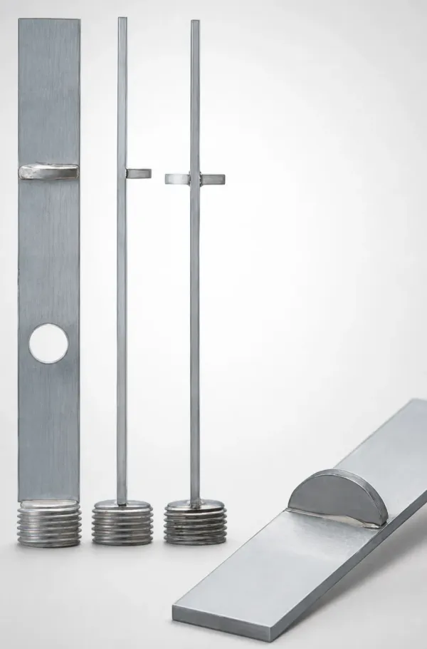
An ejector pin vent is a flat ground on the pin body. Typical practice grinds a 0.02 mm flat along part of the pin's circumference. The flat starts at the cavity surface and runs past the land. The air follows the flat down the pin body into the pin's clearance behind the cavity, then out to atmosphere.
The pin vent has two rules that keep it working. The flat must not extend into the shut-off length of the pin, or it becomes a flash path for the melt. And the flat depth stays at or below the resin's vent depth, so PA and POM pins are cut shallower than PP pins. A 0.02 mm flat that flashes on a nylon tool needs to come back to 0.01-0.015 mm.
Slides and lifters vent across their bearing faces. The air pocket ahead of the slide travels along its face. A vent slot across the slide, at 25-50 mm spacing and the resin's depth, lets it out before the slide closes. The relief behind the slide face is opened to 0.5-1.0 mm so the air has a path once it passes the land.
Lifter venting follows the same logic. The lifter face forms an undercut or a deep wall, and the far end of that face is often the last-fill point. A shallow slot at the top of the lifter, vented down its body, removes the trap without touching the parting line. These paths carry maintenance cost, since pins, slides, and lifters move and wear, but they vent features that a parting-line slot cannot reach.
When Vents Are Not Enough
Sometimes the geometry will not take a vent, or the tool is running and a vent modification is not possible before the next shift. The machine side has levers that shrink or suppress the burn. A mold maker should know them well enough to argue about them, because they treat the symptom and the vent treats the cause.
Injection speed is the first lever. A profiled speed that drops 10-30 percent near the end of fill slows the front. The trapped air gets more time to escape through whatever gap exists. Typical practice is a three-stage fill profile, with the final 10-20 percent of the shot run at the reduced speed before transfer to hold pressure.
Earlier transfer is the second lever. Switch from injection to hold at roughly 95-99 percent of fill. Run no hard mechanical stop, so packing stops driving the front into the air pocket. The pocket compresses less, so the gas heats less. This works only when the part still packs out, which a short-shot check at 95 percent confirms.
Vacuum venting is the mold-side answer for stubborn tools. The cavity is sealed and evacuated to roughly -0.8 to -0.95 bar before fill. There is no air left to compress. Vacuum venting earns its cost on high-cavitation and deep-rib tools where normal vents cannot keep up. The price is seals, a vacuum unit, and longer cycle handling.
Cascade or valve gates shrink the problem by shortening the flow. Each gate opens as the flow front passes it, so the part fills in segments and each segment's last-fill point vents more easily. Parts above roughly 300-500 mm in length, and cosmetic parts where a single front would trap air at the far end, are the typical candidates. The trade is gate cost and a hot runner controller, which our hot runner articles cover in detail.
None of these levers replaces a vent at the trap. They are interim controls that get a trial moving or a run delivered while the steel modification is scheduled. The vent remains the permanent fix, because it removes the compression event that the other levers only soften.
Trial Workflow: Short Shots First
The trial sequence that finds burn marks is the same sequence that finds short shots, and it costs about an hour of press time. Run staged short shots at roughly 50 and 80 percent fill before any full shot. The 50 percent shot proves the feed system, and the 80 percent shot shows which ribs, bosses, and corners fill last.
Mark every last-fill point on the drawing as you watch the shots. Those points are the air trap map of the cavity, and every one of them needs a vent path before production speed becomes the goal. If the tool already has vents, the staged shots verify that each trap has a slot at the resin's depth.

Then run the full shot. A clean full shot at the production injection speed confirms the vents work. A burn at the mapped trap means the vent there is missing, too shallow, or clogged, and it goes back to the bench. A burn that appears only at high speed, then clears when the last 10-20 percent of fill slows, is a marginal vent. It needs depth or width, not a new trap.
The workflow belongs in the trial protocol, not improvised on the floor. A professional T0/T1/T2 sequence stages the shots, documents the vent map, and signs off the burn-free full shot before first article inspection. Our T1 mold trial service runs exactly this sequence, and it is where a burn-prone tool gets caught before it ships to production.
Two verification numbers close the loop. The cosmetic A-surface reject target for production sits near 1-2 percent. The vent layout should hold the trial below that from the first full shot. Vent depth is a measured value, not a guess. Check it with a 0.02-0.05 mm feeler leaf or a silicone cast of the slot.
Maintenance: Vents That Stop Venting
A vent that worked at T1 can be dead by the third production week, and the burn returns exactly where it left. Vents clog because the resins that need them most deposit the most residue. Off-gassing materials like POM, PA, and PVC release volatiles during processing, and those condensates build up in the shallow slot until the air cannot pass.
POM is the classic case. It degrades above roughly 230 °C and releases formaldehyde, which condenses as a whitish deposit in the vent land. PVC releases hydrogen chloride at high processing temperature. Nylon releases moisture and volatiles that bake onto the steel. A slot cut at 0.02 mm deep has almost no cross-section to spare, so a thin deposit can stop it entirely.
Cleaning belongs in the maintenance schedule with a fixed interval. Typical practice for off-gassing resins is vent cleaning every production run or weekly, whichever comes first, and at every mold maintenance cycle. A brass brush, a soft pick, or an ultrasonic bath of 15-30 minutes clears the slot without widening it.
Never clean a vent with anything that removes steel. Abrasive blasting and aggressive scraping widen the slot past the resin's depth limit. A vent that grows from 0.02 mm to 0.04 mm on a nylon tool starts flashing while it vents. Check the depth after every cleaning with feeler gauges in the 0.02-0.05 mm range, and re-cut the land when the check shows wear.
Polish the land when the mold comes in for maintenance. The land surface should stay smooth so the melt does not stick and tear as it passes the slot. If the tool has ever flashed and the flash was ground off, the vent land is damaged at that spot. Measure it before the mold goes back in the press.
FAQ: Burn Marks in Injection Molding
Q1. What causes black burn marks on injection molded parts?
Dieseling. Trapped air at the last-fill point is compressed by the melt front at ratios of roughly 8-10:1. The gas heats adiabatically to 400-700 °C. The polymer chars, because most thermoplastics degrade in the 280-330 °C band. The fix is a vent at the trap, cut to the resin's depth, so the air escapes instead of compressing.
Q2. Where do burn marks usually appear on a part?
At the last-fill points of the cavity. The typical sites are rib ends, boss tips, blind cores, the far side of weld lines, and the region opposite the gate. Each of those locations traps air when the flow fronts close around it, so each one needs its own vent path.
Q3. How deep should vents be for my resin?
Match the resin's viscosity. PP/PE run at 0.02-0.04 mm, ABS at 0.03 mm, PC at 0.02-0.04 mm, PA at 0.01-0.03 mm, POM at 0.01-0.02 mm, LCP at 0.005-0.015 mm. Keep the land at 1-3 mm and the relief at 0.5-1.0 mm. Too deep flashes, and low-viscosity resins can flash through clearances as small as 0.01-0.02 mm at shut-offs.
Q4. How do I tell a burn mark from black specks or splay?
Location and repeatability. A burn sits in the same last-fill spot on every cycle and is charred into the surface. Black specks appear at random locations and come from degraded material in the barrel, screw, or regrind. Splay shows as silvery streaks near the gate and comes from moisture. Drying at the resin's spec removes it, such as 120 °C for 3-4 hours for polycarbonate.
Q5. Can machine settings fix burn marks without adding vents?
Partially, and only as an interim control. Dropping injection speed 10-30 percent near the end of fill reduces the compression of the air pocket. Transferring to hold at 95-99 percent of fill does the same. The burn may disappear at lower speed, but the trap is still there, and it returns the moment production speed does. The vent is the permanent fix.
The Bottom Line
A burn mark is a venting failure at the last-fill point, and it repeats every cycle until the mold vents it. Cut slots to the resin's depth, prove them with short shots, and keep them clean. DieStrike builds molds to ±0.005 mm under IATF 16949, shipping in 2-5 weeks.
Send your part file for a 24-hour DFM review, and the air traps get mapped before the steel is cut. Contact DieStrike to start the review.
KEEP READING
Related Reading
How to Prevent Flash: Shut-Offs, Vents and Clamp Tonnage
A vent cut too deep trades burn marks for flash. Shut-off limits near 0.01-0.02 mm and the clamp-tonnage side of the balance.
Read articleArticleHow to Run a Mold Trial: T0, T1, T2 and First Article Approval
Burn marks surface on trial day. A staged T0/T1/T2 trial catches air traps with short shots before full-speed shots scrap parts.
Read articleArticleMold Flow Analysis: When It Pays in Mold Design
Fill simulation predicts last-fill points and air traps before steel is cut. Where analysis pays for itself on burn-prone tools.
Read articleServiceMold Trial & T1 Sampling
Professional mold trial services with T0/T1/T2 milestones, short-shot staging, vent verification, and burn-free sampling before shipping.
Read articleNEXT STEP
Ready to Start Your Mold?
Send us your element dimensions or part numbers — our team responds within 24 hours with pricing and lead time.

Written by
Ray ChanMold Buyer's Guide Author · Precision Mold Manufacturing Specialist. Ray helps global importers, distributors and OEMs source factory-direct molds and mold parts.