
Mold to Machine Compatibility Checklist: 12 Checks Before You Cut Steel
Table of Contents
A 16-cavity connector mold lands on the shop floor at 07:40 for a 250 t press. The base is 620 mm wide, the machine tie bars sit 560 mm apart, and the tool does not enter the press. The ejector plate is drilled for 2 rods on 100 mm centers while the machine drives 4 rods on a 150 mm square. The locating ring is Ø 100 mm against a Ø 120 mm platen bore. Three separate interfaces, three separate fixes, and T1 slips by 11 working days. Plate rework, a new ejector plate and a new ring add roughly $3,400 in parts and 26 hours of machine downtime.
None of those failures relate to mold quality. The tool was precise, the steel was right, and the cavities were spot on. The problem was an interface mismatch between the mold and the press that would run it. This is the cheapest class of mold error to prevent, because every check happens on a drawing or with a tape measure before any steel is cut.
This guide gives you the 12 interface checks to run before a mold is built or moved, with numeric pass criteria for each. It covers tie bar spacing, platen footprint, mold height, opening stroke and daylight, ejector pattern and stroke, nozzle radius, locating ring, shot capacity, injection unit, crane capacity, and utility ports. Clamp tonnage sizing is a different discipline and lives in our guide on how to calculate clamp tonnage. That article answers how big a machine you need. This article answers whether a specific machine will accept a specific mold.
The Snapshot
- Tie bar clearance: keep 20 mm minimum and 40 mm preferred between the mold base outer edge and the tie bar on each side. Below 20 mm the tool will not slide in.
- Mold height must sit inside the machine window, typically 200 to 550 mm on a 250 t press. A tool 20 mm below the minimum needs a spacer plate, which adds 1 to 3 days.
- Ejector pattern mismatch is the most common failure. Rod hole centers must align within ±0.5 mm, and a wrong pattern means a new ejector plate at $400 to $1,200.
- Nozzle radius must match the sprue bush radius within 0.5 mm, and the sprue bush orifice runs 0.5 to 1.0 mm larger than the nozzle orifice.
- Keep shot weight at 20 to 80 percent of barrel capacity. A 320 g polystyrene rating covers a 198 g part plus runner combination at 62 percent.
- Every interface recorded before transfer costs 2 to 4 hours. Every interface discovered after transfer costs 3 to 10 days and $800 to $4,000.
Why Mold to Machine Checks Fail
Most compatibility failures are inherited, not created. A mold is designed for a 250 t press on a spreadsheet, built over 3 to 5 weeks, and then scheduled on whatever machine is free that week. Nobody re-opens the machine spec sheet at that point, because the assumption is that one 250 t press matches another. They do not.
Two 250 t injection machines from different builders can differ by 40 mm in tie bar spacing, 80 mm in maximum mold height, and 60 mm in platen bolt pitch. Injection units differ more. A machine with a Ø 36 mm screw and a 1,900 bar injection pressure ceiling behaves nothing like a machine with a Ø 45 mm screw at 1,600 bar, even at the same clamp force. The clamp unit is only half of the compatibility question.

The cost curve is steep and asymmetric. A drawing review that catches a tie bar problem costs a 30-minute conversation. The same problem found at the press costs a crane lift, a returned mold, a base re-machine or a plate replacement, and a rescheduled trial. For a mold already in transit between plants, add shipping both ways at $300 to $1,500 per move.
There is a second failure mode that gets less attention: partial fit. The mold enters the press and clamps, so the setup technician signs off. Then the locating ring bore has 0.4 mm of play, the sprue starts burring after 8,000 shots, and the nozzle drools. Or the ejector rods hit the plate off-center by 1.5 mm and the plate cracks at 40,000 cycles. These faults surface weeks later and get blamed on the mold, not on the interface.
The 12-Point Compatibility Checklist
Run the 12 checks in order. The first four are gate checks that decide whether the tool physically enters and closes in the press. The middle four govern melt delivery and part removal. The last four cover handling and services. The machine figures below are typical for the tonnage band shown and must be replaced with the actual nameplate data before you commit.
| # | Interface Check | Typical Machine Value (250 t) | Mold Requirement | Fail Symptom |
|---|---|---|---|---|
| 1 | Tie bar spacing | 560 x 560 mm inner span | Base plus 40 mm clearance | Mold will not enter press |
| 2 | Platen size and bolt pitch | 700 x 700 mm platen, 125 mm T-slot pitch | Base footprint 60 to 90 percent of platen | Clamp slippage, platen deflection |
| 3 | Minimum and maximum mold height | 200 to 550 mm | Cold stack height inside window | No clamp force, tie bar alarm |
| 4 | Opening stroke and daylight | 900 mm maximum daylight | Height plus required opening under daylight | Part cannot drop free |
| 5 | Ejector pattern | Rod holes on 150 x 150 mm square, Ø 35 mm | Ejector plate holes match centers within ±0.5 mm | Rods miss plate, plate cracks |
| 6 | Ejector force and stroke | 45 kN force, 150 mm stroke | Stroke covers part height plus 20 mm | Parts stick, manual removal |
| 7 | Nozzle radius and sprue bush R | Nozzle R 15 mm, orifice Ø 4 mm | Bush R within 0.5 mm, orifice 0.5 to 1.0 mm larger | Sprue flash, drool, cold slug |
| 8 | Locating ring | Platen bore Ø 100 mm H7 | Ring OD within 0.1 mm of bore | Nozzle misalignment, sprue burr |
| 9 | Shot capacity | 320 g polystyrene rating | Part plus runner is 20 to 80 percent of rating | Short shots or resin degradation |
| 10 | Injection unit and screw | Ø 40 mm screw, L/D 20:1, 1,800 bar ceiling | Required pressure and fill rate inside ceiling | Underfilled thin walls |
| 11 | Crane and mold weight | 2 t shop crane, 1,800 kg platen load limit | Tool mass at 80 percent of crane rating or less | Crane overload, platen bending |
| 12 | Utility ports and clearances | 6 water ports, 2 core pull circuits, 1 air line | Every mold circuit has a machine feed | Dead cooling circuits, slow cycle |
← swipe to scroll →
Table note: machine values are typical figures for a 250 t class servo-hydraulic press. Always replace with the actual machine nameplate and platen drawings before tool design freeze.
Checks 1 and 2: Tie Bar Spacing and Platen Size
Tie bar spacing is the inner distance between the four tie bars, measured at the narrowest point. That number sets the absolute maximum mold base width and height. Measure all three spans, not just one, because wear plates, tie bar nuts and safety covers reduce the effective opening on some machines. A 560 mm nominal span can behave like 548 mm once covers are fitted.
Apply a clearance rule of 20 mm minimum per side and 40 mm preferred. A 480 x 420 mm base in a 560 mm span leaves 40 mm per side, which is comfortable for hand loading and fine for a forklift or die cart. A 530 mm base leaves 15 mm per side and will drag, gall the platens and put dents in the tie bars. For square tools larger than the span in one direction, check the diagonal and consider a wider machine rather than a removable tie bar.
Platen size and bolt pitch come next. A mold base that covers 60 to 90 percent of the platen spreads clamp force across the platen face and limits bending. A small tool on a huge platen loads the center and bows the platen over time, which shows up later as flash in the middle of the part. Check the T-slot pitch against the mold base bolt holes, then confirm the clamp strap positions clear the mold's water manifolds and side actions.

One quiet risk sits in the bolt pattern. Many machines use a 125 mm pitch grid with M16 or M20 T-slots, while mold bases from different standards land on 100 mm or 150 mm hole patterns. If the mold base holes miss the T-slots, the setup crew clamps with the nearest points and the tool lifts slightly under injection pressure. That movement opens the parting line, and the flash appears on the first shot after every changeover.
Checks 3 and 4: Mold Height and Opening Stroke
Mold height, also called stack height, is the cold assembled thickness from the locating ring face to the clamp plate back face. It must sit between the machine minimum and maximum mold height. The 250 t window runs about 200 to 550 mm in typical machines, and the window shifts with the clamp unit type. Toggle machines and hydraulic machines from the same tonnage band can differ by 30 to 60 mm at the minimum.
Below the minimum, the toggle cannot generate full clamp force and you need a spacer plate. Spacers run 10 mm to 50 mm thick, cost $200 to $600, and add 1 to 3 days to commissioning. Above the maximum, the machine simply will not close. There is no workaround short of machining plates down, which is a rebuild, not a shim.
Opening stroke and daylight decide whether the part drops clear. Required opening equals twice the part depth plus runner length plus 25 to 50 mm of safety. A 120 mm deep connector housing needs about 320 mm of opening, so the daylight must cover mold height plus 320 mm. A 400 mm tall tool needs 720 mm of daylight, and a 900 mm daylight machine has room. Add 50 mm whenever a robot gripper or conveyor enters the gap.
Measure the stack height with the tool cold, assembled, and sitting flat. Do not use the drawing dimension, because a 2 mm gasket, a hot runner manifold expansion gap or a pressure pad can shift the real number. Every millimeter counts at the minimum mold height limit, and a tool that measures 198 mm against a 200 mm limit needs the spacer before the crane arrives.
Checks 5 and 6: Ejector Pattern and Ejector Stroke
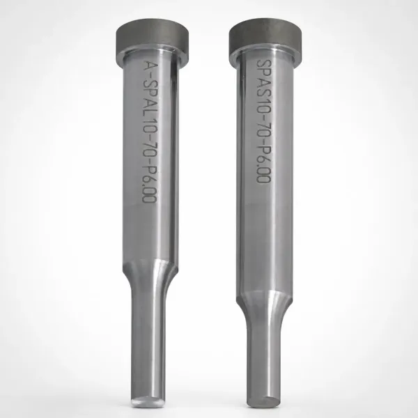
The ejector pattern is the arrangement of holes in the machine's movable platen that pass the ejector rods through to the mold's ejector plate. Common patterns are 2 holes on 100 to 150 mm centers for small presses, a 4-hole square from 150 x 150 mm to 300 x 300 mm for mid presses, and centered or offset variants that follow the hydraulic knock-out position. Rod diameters run Ø 25 to Ø 50 mm with M16 to M30 threads.
The mold's ejector plate must be drilled to accept that pattern exactly. The pass criterion is a center alignment within ±0.5 mm. Beyond that, the rod pushes off-center, the plate bows, and the pin heads start walking in their pockets. On a 16-cavity tool with 64 ejector pins, a 1 mm off-center push is enough to break the plate at 30,000 to 50,000 cycles. A replacement ejector plate costs $400 to $1,200 plus 5 to 10 days, and the mold has to come out of the press.
Ejector force and stroke are the second half of the check. Machine ejection force in the 250 t band typically runs 40 to 60 kN, which is ample for most parts. Stroke is the constraint. Required ejector stroke equals part depth plus 10 to 20 mm of clearance for the part to fall free. A 180 mm tall bucket needs roughly 200 mm of stroke, and many mid-range machines stop at 150 mm. When the numbers do not line up, the options are a stripper plate design, a two-stage ejection plate in the tool, or a different machine.
Ejector systems deserve their own design pass, and the placement rules for pin size, draft and pocket depth are covered in our guide on how to design ejector systems. The machine check here is narrower: pattern, rod thread, force and stroke. Those four numbers decide whether the tool in the drawing can be ejected by the press on the floor.
Checks 7 and 8: Nozzle Radius and Locating Ring
The nozzle radius is the spherical radius on the machine nozzle tip. The sprue bush radius is the matching concave sphere in the mold. These two surfaces must seat against each other with no gap and no interference. The rule is simple: match the radii within 0.5 mm, and keep the sprue bush radius equal to or 0.5 mm larger than the nozzle radius. A typical mid-size machine nozzle carries R 15 mm with a Ø 4 mm orifice, and the sprue bush runs R 15 mm with a Ø 4.5 to Ø 5.0 mm orifice.
Get the radii wrong in either direction and the failures are different. A nozzle radius smaller than the bush radius leaves a ring gap where melt escapes, which shows up as a sprue well flash ring and stringing. A nozzle radius larger than the bush radius digs into the bush face, cold slugs form, and the sprue sticks on every shot. The orifice relationship matters too: the sprue bush orifice runs 0.5 to 1.0 mm larger than the nozzle orifice, so the cold slug pulls cleanly and the pressure drop stays low.
Sprue bush selection by cavity count and gate architecture is covered in our guide on how to select sprue bushings. For machine compatibility, record three numbers: nozzle radius, nozzle orifice diameter, and the distance from the nozzle tip to the platen face.
The locating ring centers the mold on the platen and aligns the sprue bush with the nozzle. Platen bores are typically Ø 100 mm or Ø 120 mm on mid presses, with a smaller Ø 63.5 mm or Ø 100 mm pattern on small machines. The ring outer diameter must fit the bore within 0.1 mm. Standard rings are usually located by four screws and often left undersized by 0.5 mm for easy loading, which is exactly the wrong call on a precision connector tool. A 0.5 mm ring gap allows the mold to shift under injection pressure, and the nozzle then loads the sprue bush off-axis, which produces a burr on the sprue face within a few thousand shots.
Checks 9 and 10: Shot Capacity and Injection Unit
Shot capacity is the maximum mass of polystyrene the barrel can inject in one stroke, expressed in grams. Convert your actual resin mass back to that basis before comparing. Rough density factors against polystyrene sit near 1.0 for PS, 1.05 for ABS, 1.15 for PA, 1.20 for PC and 1.40 for POM. A 55 g polycarbonate part plus a 12 g runner equals 67 g of PC, which converts to about 80 g of polystyrene equivalent.
Then apply the 20 to 80 percent window. Below 20 percent, melt residence time climbs and the resin degrades in the barrel. Above 80 percent, the screw cannot recover in time and the cycle stretches or the shot shortens. A 320 g polystyrene machine comfortably runs the 80 g equivalent shot at 25 percent, and there is plenty of headroom. A 90 g machine would run the same shot at 89 percent and would short-shot on a cold morning.
The injection unit check goes beyond capacity. Three numbers decide thin-wall and precision work: injection pressure ceiling in bar, injection rate in cubic centimeters per second, and screw diameter with its L/D ratio. Typical mid-size units run 1,600 to 2,000 bar with L/D ratios near 20:1. If the part needs 1,500 bar at the nozzle and the machine ceiling is 1,700 bar, the margin is thin once you add pressure loss through the sprue, runner and gates.
There is also a plasticating limit that spec sheets bury. The barrel must melt the shot in the cooling time, not in the whole cycle. If plasticating rate is 22 g per second and the shot is 198 g, the screw needs 9 seconds of recovery. When cooling time is only 12 seconds, recovery eats most of the cycle. Always check the recovery time, not just the rated shot weight.
Checks 11 and 12: Crane Capacity and Utility Ports
Mold weight is a handling and structural check. Two limits apply: the crane or hoist rating and the platen load capacity. Keep the tool mass at 80 percent of the crane rating or less, because a mold swinging on a two-leg sling at 45 degrees adds dynamic load. Lifting eyes also carry their own limits. An M20 swivel hoist ring typically handles 1.0 to 1.5 t, an M16 ring roughly 0.4 to 0.7 t, and a four-point lift spreads the load only when the sling angles stay near vertical.
The platen limit is quieter and more expensive. Platen bending under a heavy tool shows up as flash in the middle of the part and premature wear in the mold base. A 620 kg tool on a machine rated for 1,800 kg total mold load is fine on paper. Add a 1,200 kg tool on the same machine over years of use and the platen bows permanently. Always record the mold half weights separately, since the moving half carries the ejector system and often outweighs the fixed half by 15 to 25 percent.
Utility ports close the list. Count the mold cooling circuits and confirm the machine or chiller manifold can feed each one. Most mid presses supply four to eight water circuits at 3/8 inch or 1/2 inch ports, plus one or two hydraulic core pull circuits and one or two air lines. A mold with 10 cooling circuits on a machine with 6 feeds runs 4 circuits dead, and the cycle time climbs 8 to 20 percent. Check the thread standard as well, since BSP and NPT fittings do not interchange, and a forced fit leaks onto the platen.
Clearances finish the job. Confirm 100 to 150 mm of space for hot runner controller cables, room for the robot gripper, and a drop area at least 50 mm larger than the part in each direction. Also check the safety gate path, because a mold that overhangs the platen can block the gate interlock on some machines.
What Clamp Tonnage Does Not Tell You
Clamp tonnage sizing answers one question. Can the machine hold the mold closed against the force that pushes it apart? That calculation multiplies projected area by cavity pressure in tons per square inch, then adds a 1.1 to 1.2 safety factor. A 16-cavity connector tool with 33 square inches of projected area at 3 tons per square inch needs about 100 t of clamp force, so a 150 t machine passes with margin.
Passing that math proves nothing about fit. A 150 t press can clear the tonnage test and still reject the mold on tie bar spacing, minimum mold height, ejector pattern and nozzle radius. The two checks are independent, and both are mandatory. Treat the tonnage calculation as machine selection and the 12 checks as interface validation.
There is one overlap, and it catches people out. Cavity layout affects both. Spreading cavities wide increases projected area and raises the required clamp force, while also pushing the base dimensions toward the tie bar limit. A 4-cavity layout at 60 mm pitch may pass the tonnage check and fail the tie bars on the same press. Settle the cavity layout first, then run both checks in parallel, not one after the other.
Measure and Record Before You Move the Mold
For a transfer between plants or between machines, the 12 checks become a measurement job. Budget 2 to 4 hours with a tape measure, radius gauges, calipers and a camera. Record every value on one sheet, then compare it against the mold drawing and the machine specification before the crane lifts anything. The measurement cost is trivial next to a failed transfer.
Measure the machine side first, because that data rarely changes and can be reused for every future tool on that press. Then measure the mold side on the cold, fully assembled tool. The table below lists what to record, how to take the reading, and the acceptance limit that decides go or no-go.
| Measurement | How to Take It | Acceptance Limit |
|---|---|---|
| Tie bar inner span | Tape across the narrowest span at three points | Mold base 20 mm clear per side minimum |
| Platen face and T-slot pitch | Measure center to center on two adjacent slots | Base holes land on slots without strap shims |
| Mold height, cold | Calipers from locating ring face to clamp plate back | Inside machine minimum and maximum window |
| Maximum daylight | Dry cycle the press open and measure the clear gap | Mold height plus required opening, plus 25 mm |
| Ejector rod pattern | Hole centers, hole diameter and rod thread size | Centers align within ±0.5 mm |
| Ejector stroke | Machine screen value plus physical measurement | Part height plus 10 to 20 mm |
| Nozzle radius and orifice | Radius gauge on the tip, pin gauge in the orifice | Bush R within 0.5 mm, orifice 0.5 to 1.0 mm larger |
| Platen bore and locating ring | Bore gauge on the platen, micrometer on the ring | Clearance 0.1 mm or less |
| Shot capacity | Nameplate grams of polystyrene, converted by resin factor | Part plus runner at 20 to 80 percent of rating |
| Injection pressure and rate | Machine spec sheet, then the last setup sheet values | Required pressure at least 15 percent below ceiling |
| Mold mass per half | Crane scale or plate calculation from the drawing | 80 percent of crane rating or less |
| Cooling and aux circuits | Count and thread-check every mold port and machine feed | No dead circuit, matching thread standard |
← swipe to scroll →
Table note: acceptance limits are industry-typical figures for precision injection tooling in the 100 to 400 t range. Tighten them for connector, medical and optical cavity tolerances.
Two habits make the record reliable. Photograph the machine nameplate, the platen face and the ejector pattern in one frame with a tape measure visible for scale. Then store the sheet with the mold documentation, so the next transfer starts from facts instead of a phone call to the last technician who ran the tool.
For a mold that has already run, add one more step. Pull the last setup sheet and compare the actual process values against the new machine ceilings. A job that ran at 1,650 bar on a 2,000 bar machine may not run at all on a 1,600 bar machine. That single number has cancelled more transfers than any structural dimension.
The trial run is the proof step. The protocol inside mold trial and T1 sampling covers the clamped-in checks once the tool is connected to water, hydraulics and air.
Compatibility Red Flags and Remedies
These are the mismatches that come up most often, with the practical fix and its cost. Fix them before the crane moves, because none of these get cheaper at the press.
Clearance under 20 mm per side. The tool will not load cleanly. Move the job to a wider machine, or reduce base width 20 to 30 mm where the bolt pattern and side actions allow. Never grind the base for clearance, since the mold base carries the ejector and guide alignment.
Stack height below the machine minimum by 10 to 50 mm. Fit a spacer plate. Cost runs $200 to $600 with 1 to 3 days of lead time, and the spacer must be flat within 0.02 mm across the face to avoid tipping the mold under clamp load.
Ejector pattern off by more than 0.5 mm. Drill a new ejector plate at $400 to $1,200 and 5 to 10 days. Adapter plates exist but add a stack-up error of 0.1 to 0.3 mm, which matters on thin parts. Fix the plate if the tool is going into long production.
Nozzle radius mismatch over 1 mm. Change the nozzle tip, not the sprue bush. A nozzle tip costs $150 to $400 and swaps in an hour. Re-cutting the bush face in place removes case depth and shortens bush life on the sprue seat.
Shot weight under 20 percent of barrel capacity. Move the tool to a smaller injection unit where the machine allows an A, B or C barrel swap. The change takes 4 to 8 hours. Staying on an oversized barrel risks degradation, black specks and rejected parts in resins such as PC and POM.
Mold mass over 80 percent of crane rating. Use a larger hoist or a two-crane lift with a spreader beam. Adding counterweight to a mold is not a fix, because it increases platen load and mold height at the same time.
Fewer cooling feeds than mold circuits. Fit a manifold with flow splitters and accept an 8 to 20 percent cycle penalty, or move to a machine with more feeds. Parallel circuits that share one supply will starve the last circuit and create uneven mold temperature.
Mold to Machine Compatibility FAQ
Q1. What is the most common mold to machine mismatch?
Ejector pattern. In transfer work, roughly 1 in 3 tools arrives with rod hole centers that miss the machine pattern by 0.5 to 3 mm. The fix is a new ejector plate at $400 to $1,200 and 5 to 10 days, so confirm the pattern before the tool leaves the bench.
Q2. Can a spacer plate fix a mold that is too short for the press?
Yes, up to about 50 mm. A spacer of $200 to $600 restores the minimum mold height, and it must be flat within 0.02 mm. Beyond 50 mm the stack loses rigidity, and the better answer is a different machine.
Q3. How much tie bar clearance does a mold need?
Keep 20 mm minimum and 40 mm preferred per side. Below 20 mm, hand loading risks tie bar scoring and guide pin damage. Measure the real span with covers and wear plates fitted, not the nominal nameplate figure.
Q4. Does matching clamp tonnage guarantee a mold fits a machine?
No. Clamp tonnage only confirms the press can hold the tool closed. Tie bar spacing, mold height, daylight, ejector pattern, nozzle radius, locating ring and shot capacity are separate checks, and any one of them can reject an otherwise correct tonnage match.
Q5. How long does a proper compatibility review take?
Two to four hours on the shop floor with gauges and a tape measure for a transfer job. On a new build, the same 12 checks take 30 to 60 minutes at the drawing stage, before steel is cut.
The Bottom Line
A mold that fits one press will not automatically fit another. Twelve interface checks, each with a numeric limit, cost 2 to 4 hours before transfer and prevent 3 to 10 days of downtime after it. DieStrike builds and validates molds to ±0.005 mm with machine interface review inside 24-hour DFM feedback. Share your press list at our contact page before design freeze.
KEEP READING
Related Reading
How to Calculate Clamp Tonnage: Projected Area, Cavity Pressure, Safety Margin
The projected area and cavity pressure math that sizes a machine, the companion discipline to interface checking.
Read articleArticleHow to Design Ejector Systems
Ejector plate layout, pin placement and stroke rules that must match the machine ejection pattern.
Read articleArticleHow to Specify a Mold Base for ±0.002mm Tolerances
Mold base sizing, platen footprint and locating ring choices that drive machine compatibility.
Read articleServiceMold Design and DFM
DFM feedback in 24 hours, machine interface reviews and ±0.005 mm mold build precision.
Read articleNEXT STEP
Ready to Start Your Mold?
Send us your element dimensions or part numbers — our team responds within 24 hours with pricing and lead time.

Written by
Ray ChanMold Buyer's Guide Author · Precision Mold Manufacturing Specialist. Ray helps global importers, distributors and OEMs source factory-direct molds and mold parts.