
How to Select Sprue Bushings for High-Cavity Molds
Table of Contents
A 48-cavity connector mold began drooling on its second production day. The sprue bushing was a stock part with a 6.5 mm orifice. Its counterbore radius did not match the nozzle tip, and its centerline sat 0.18 mm off the machine axis. Operators stopped the line for cleanup three times per shift. Week one scrapped 1,100 housings. The toolmaker spent 14 hours on the press chasing a fault that belonged on the drawing board. That sequence repeats in tooling audits because sprue bushing selection is treated as a catalog order, not as an engineering decision.
A sprue bushing is the first melt-contact component in every cold runner mold. It takes the nozzle stream, tapers it into the sprue, and seals the machine-to-mold interface. On a 32-cavity tool it feeds every cavity through the runner system, so a 0.5 mm error here repeats in all 32 cavities. High-cavity molds multiply every bushing defect by the cavity count.
This guide covers sprue bushing types, steels, dimensions, orifice rules, nozzle alignment, wear limits and hot half thermal control across 16 to 64 cavity tools. Every decision stays on the mold-making side of the line: the bushing, the locating ring, the runner and the hot half. Figures are typical industry values unless marked as DieStrike capabilities.
The Snapshot
- A misaligned sprue bushing costs 2 to 3 hours of press downtime per shift and 3 to 5% scrap in the first production week, typical figures.
- Sprue small end runs 3 to 6 mm for parts from 0.5 g to 50 g, with a 1 to 3 degree taper per side.
- H13 nitrided reaches 900 to 1000 HV at the surface, S136 resists corrosive off-gassing, and beryllium copper conducts 4 to 7 times more heat than tool steel.
- Match the nozzle ball radius within 0.3 mm and hold centerline offset under 0.1 mm, or drool starts.
- DieStrike ships standard sprue bushings in 3 to 7 days and returns DFM feedback within 24 hours.
Why Sprue Bushing Selection Fails
A cold sprue and runner add 5 to 15% regrind to every shot in a cold runner mold. On a 32-cavity tool with a 150 g shot, that is 7.5 to 22 g of material ground, dried and reprocessed every cycle. The sprue bushing controls the largest single piece of that waste, the sprue itself. A well-sized bushing keeps sprue weight near 1% of shot weight.
The dominant failure modes are drool, stringing, splay and premature erosion. Drool comes from an oversized orifice or a radius mismatch at the nozzle seat. Stringing comes from a bushing that runs too hot at the head. Splay at the gate traces to moisture or shear, but a worn seat makes it worse. Each mode stops a high-cavity line while the press is cleaned, and cleanup runs 15 to 40 minutes per occurrence.
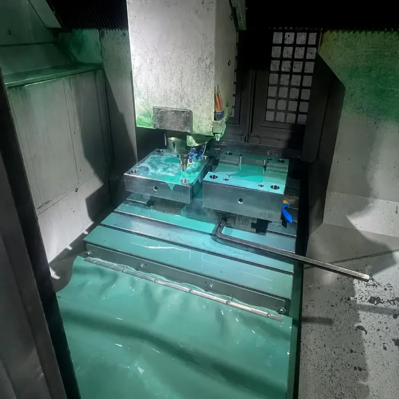
A 64-cavity mold turns one bushing defect into 64 identical defects. A 0.1 mm orifice growth that raises gate shear on one cavity becomes a 64-cavity pattern of blush and short shots. That is why connector programs from TE Connectivity, Amphenol, Luxshare and Dongshan Precision specify bushing geometry in the mold RFQ. The part tolerance is decided at the gate, and the gate starts at the bushing.
DieStrike holds mold dimensions to ±0.005 mm and component geometry to ±0.002 mm, with cavity steel at HRC 62. Sprue bushings ship to the same discipline: bore to body concentricity under 0.01 mm TIR, and a ground ball seat. Those numbers keep a 64-cavity mold balanced after 500,000 cycles.
Sprue Bushing Types
Four bushing families cover 8 to 64 cavity cold runner and hot half designs. The choice starts with the runner strategy, then the reach, then the thermal job the bushing must do.
Standard sprue bushing
The standard bushing is a head, a straight body and a tapered bore. Body diameters run 12, 16, 20 and 25 mm, and the head registers in the locating ring bore. It suits 8 to 32 cavity cold runner molds with a 40 to 150 mm plate stack. It is the cheapest option and a stock item from our sprue bushing line, with a 3 to 7 day lead time.
Extended sprue bushing
Extended bushings add body length to reach through thick platens, stack molds or insulation plates. Lengths run 100 to 250 mm, and the body needs support to stop bending under nozzle load. Use an extended bushing only when the standard length cannot reach the parting line. Bending shows up as a crescent wear pattern at the gate end.
Insulated sprue bushing
An insulated bushing keeps melt fluid with a thin frozen skin on the bore wall instead of a heater. The bore runs 3 to 5 mm, which keeps the frozen layer thin enough to re-melt on every shot. It fits short cycles and low melt temperature resins like PP and PE. It costs 30 to 50% less than a hot sprue bushing and needs no controller zone.
Hot sprue bushing
A hot sprue bushing replaces the cold sprue with a heated, insulated melt channel. A 150 to 400 W heater band and a J or K thermocouple hold the zone within ±2 to 5 °C. High-cavity tools use hot sprue bushings to eliminate regrind and shorten cycles. The trade is cost, a controller zone and thermal expansion management.

The table below maps 6 common high-cavity applications to a starting selection. Treat the row as a first pass, then verify the orifice against the part weight and the resin data sheet.
| Application | Bushing Type | Material | Orifice (Small End) | Note |
|---|---|---|---|---|
| 8-16 cavity general parts, ABS, PP, PE, up to 30 g | Standard | H13, 48-52 HRC | 4-5 mm | Default choice, 2 degrees per side taper, 3-7 day lead time |
| Thin-wall caps and closures, 16-64 cavities | Standard or insulated | S136 | 3-4 mm | Insulated bore cuts regrind and speeds the cycle |
| Glass-filled PA66 or PBT housings, 16-64 cavities | Standard, nitrided | H13 nitrided to 900-1000 HV | 4-6 mm | Nitriding lifts erosion life 2 to 3 times vs bare H13 |
| Corrosive resins, PVC, POM, FR-ABS | Standard | S136, 48-52 HRC | 3-5 mm | Stainless resists off-gas attack at the seat |
| Thick platen or stack mold | Extended | H13 | 4-6 mm | Lengths 100-250 mm, support the body to stop bending |
| High-volume, regrind-sensitive programs, 32-64 cavities | Hot sprue | H13 with beryllium copper tip | 3-5 mm | 150-400 W heater, ±2-5 °C zone, removes the cold sprue |
← swipe to scroll →
Table: typical industry figures; verify against your program.
H13, S136 and Beryllium Copper
Three material families cover nearly every sprue bushing application across 16 to 64 cavity tools. Steel choice follows the resin, the abrasive load and the thermal job, in that order.
H13 hot-work steel
H13 (1.2344) hardens to 46 to 52 HRC and keeps toughness at high mold temperature. Nitrided to 900 to 1000 HV, the surface resists the abrasion of glass-filled PA66, PBT and LCP. Industry figures put a nitrided H13 bushing at 500,000 to 2,000,000 cycles with 30% glass filler. Unnitrided H13 on the same resin erodes 2 to 3 times faster.
S136 stainless
S136 (AISI 420 modified) runs 48 to 52 HRC and resists the corrosive off-gassing of PVC, POM and flame-retardant ABS. It polishes to a mirror finish, which slows deposit buildup at the seat. Use S136 when the resin chemistry attacks the bore or when the shop runs humid conditions. Thermal conductivity sits near 25 W/mK, slightly below H13.
Beryllium copper
Beryllium copper (C17200) runs 36 to 42 HRC with thermal conductivity near 105 to 130 W/mK. Compare that to roughly 28 W/mK for H13, a 4 to 7 times advantage. Use it for insulated bushings, hot sprue tips and gate-adjacent cooling. It costs 4 to 8 times more than P20-grade steel, so spend it only where heat transfer pays.
| Material | Hardness | Thermal Conductivity | Best For | Watch Out |
|---|---|---|---|---|
| H13 (1.2344) | 46-52 HRC, nitrided to 900-1000 HV | ~28 W/mK | Glass-filled and high-temperature resins | Needs nitriding or coating for abrasive melts |
| S136 (AISI 420 mod) | 48-52 HRC | ~25 W/mK | Corrosive and transparent resins | Lower toughness than H13 |
| Beryllium copper C17200 | 36-42 HRC | ~105-130 W/mK | Hot sprue tips and insulated bushings | 4-8x the cost of P20, use only for heat transfer |
← swipe to scroll →
Table: typical industry figures; verify against your program.
The vertical rule is simple. Match the steel to the melt that touches it, and match the conductivity to the heat that must move. P20 at 28 to 32 HRC has no place in a sprue bushing on an abrasive or corrosive program.

DieStrike grinds sprue bushings from H13, S136 and beryllium copper blanks at ±0.002 mm geometry, with the same steel sourcing used for custom mold inserts. For a full steel comparison across P20, H13 and S136, see the related reading at the end of this guide.
Critical Dimensions
A sprue bushing drawing carries 5 dimensions that decide whether the tool runs. Each one maps to a failure mode if it drifts.
Body O-diameter
The body diameter registers the bushing in the sprue plate bore. Standards run 12, 16, 20 and 25 mm, and the fit keeps the bore concentric with the machine nozzle. A loose fit lets the bushing shift under nozzle load. Hold the body-to-bore fit to H7/h6 class, typical industry practice.
Ball radius R
The counterbore at the head seats the machine nozzle tip. Standard nozzle ball radii are 12.7 mm (1/2 in) and 19 mm (3/4 in). Spec the counterbore radius equal to the nozzle radius within +0.05 mm. A mismatch beyond 0.3 mm opens a gap where melt hangs, strings and drools.
Orifice and taper
The bore small end sets the melt delivery rate, and the taper sets the pressure transition. Small end runs 3 to 6 mm for typical parts, and taper runs 1 to 3 degrees per side. The taper also lets the sprue release from the bushing on ejection. A zero-taper bore sticks the sprue and stalls the cycle.
Length
Overall length runs from the head seat to the parting line, typically 40 to 150 mm. It must clear the full plate stack with 1 to 2 mm of margin. Too short and the nozzle cannot reach the seat. Too long and the bushing presses into the runner or the cavity plate.
Locating ring
The locating ring centers the mold on the machine platen and carries the bushing head. Standard OD is 100 mm, held to 99.95 to 100 mm, seated in the platen spru hole. The bushing head must register inside the locating ring bore, not float in the plate. That fit stack decides nozzle-to-bushing alignment, and it belongs to the same fit chain covered in our guide on how to specify a mold base.
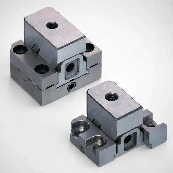
DieStrike grinds locating rings and bushing heads to the same ±0.002 mm geometry class as the rest of the standard parts line. Concentricity between the head, the body and the bore holds under 0.01 mm TIR. Ask for the concentricity report with the part, it is a one-page CMM check.
Orifice Sizing Rules
Orifice sizing follows the shot weight and the resin, not habit. The small end runs 3 to 6 mm. The taper runs 1 to 3 degrees per side. Together they set the pressure drop at the start of the flow path.
The 3 to 6 mm rule
A 3 to 6 mm small end covers parts from 0.5 g to 50 g, which spans most connector housings, caps and medical components. Below 3 mm the melt shear climbs and the bushing erodes faster. Above 6 mm the sprue gets heavy and slow to freeze, and the regrind fraction grows.
Taper per side
Taper runs 1 to 3 degrees per side, with 2 degrees as the default. The taper converts the bore into a draft that releases the sprue and spreads the pressure drop over the bore length. Deeper tapers suit long bushings, and shallower tapers suit short reach and low pressure loss.
Worked example: 32-cavity connector housing
Take a 32-cavity PA66 GF30 connector housing at 4.5 g per part, with a 40 mm sprue length. Start the small end at 4 mm and the taper at 2 degrees per side. The large end equals 4 mm plus 2 x 40 mm x tan(2 degrees), which is 4 mm plus 2.79 mm, or 6.8 mm.
Check the large end against the runner. The sprue exit should be at least 1.2 times the primary runner diameter, so a 5 mm runner accepts a 6.8 mm exit. The sprue cone volume is about 0.94 cm³, or roughly 1.1 g of PA66 per shot. Against a 144 g shot, the sprue is 0.7% of the shot, a healthy budget for a cold runner tool.
Run the resin check last. PA66 GF30 sets the small end at 4 mm, not 3 mm, because the glass raises viscosity and shear. If the part were LCP at 330 °C, the same bushing would need a nitrided H13 bore and a 3 mm small end. Resin data sheet shear curves beat rule of thumb every time.
Nozzle Alignment
The bushing meets the machine at one point, and that point is the most common drool source in the shop. Alignment has 3 parts: the radius, the orifice step and the centerline.
R radius match
The nozzle tip ball radius must seat into the bushing counterbore radius. A 12.7 mm nozzle goes with a 12.7 mm counterbore, and a 19 mm nozzle with a 19 mm counterbore. Keep the counterbore within +0.05 mm of the nozzle radius, and verify both with a radius gage. A gap over 0.3 mm traps melt and starts stringing.
Orifice offset
The nozzle orifice should run 0.5 to 1.0 mm smaller than the sprue large end. That step keeps the melt from hanging at the interface. A nozzle orifice equal to or larger than the sprue exit leaves a ledge that cools and strings on every retraction.
Centerline
Machine nozzle center must sit within 0.1 mm of the bushing bore center. The platen spru hole must stay concentric to the locating ring bore within 0.05 mm. Check both at mold trial with a dial indicator on the nozzle body. A 0.18 mm offset, the size that started this article, produces one-sided shear, early erosion and drool at 2 to 5 g/min.

Add the alignment check to the T1 trial checklist and to every preventive maintenance interval. The check takes 10 minutes with a dial indicator. The drool cleanup it prevents takes 40 minutes per occurrence, three times a shift.
Thermal Control in Hot Halves
High-cavity hot halves move the drool and regrind problem from the melt channel to the temperature field. Across 8 to 64 drops, every zone must hold its setpoint or the gate side of the cavity drifts.
Hot sprue zones
A hot sprue bushing carries a 150 to 400 W heater band and a J or K thermocouple. Zone control holds the melt channel within ±2 to 5 °C of setpoint. On a 32-cavity hot half, the sprue zone is one of 8 to 16 controller zones. Run the sprue zone 5 to 10 °C hotter than the manifold to keep the first branch balanced.
Expansion management
Steel grows about 12.6 µm per meter per kelvin. A 300 mm hot half plate at 230 °C is 0.77 mm longer than at 25 °C. Design the expansion gap so nozzles and bushings stay sealed at operating temperature. Forget the gap and the bushing seats open, which leaks melt and drools.
Gate-side cooling
The cold half must pull heat from the gate area while the hot half keeps the channel fluid. Beryllium copper tips bridge that job by conducting 4 to 7 times more heat than steel at the gate. Cooling circuits of 8 to 12 mm diameter within 15 to 25 mm of the sprue seat keep the head temperature stable.
DieStrike supplies hot sprue bushings as components and full hot runner systems with manifolds, controllers and thermocouple cables. The hot runner catalog covers H and X manifold layouts for 8 to 64 drops. Standard items carry the same 3 to 7 day lead time.
Wear, Erosion and Replacement
Every sprue bushing wears, and the wear rate follows the resin. Glass fibers at the gate erode the orifice and open the drool path. Typical erosion runs 0.05 to 0.1 mm per 100,000 to 300,000 cycles on a glass-filled program.
Erosion at the gate end
Glass-filled resins erode the small end fastest. Industry figures show 0.05 to 0.1 mm of orifice growth in 100,000 to 300,000 cycles with 30% glass on an unnitrided bore. Nitrided H13 slows that to 2 to 3 times longer. When the orifice grows, the sprue freezes slower and the regrind fraction climbs.
Gate drool and stringing
Drool is the visible symptom of a worn or mis-seated bushing. Melt drips from the nozzle seat at 2 to 5 g/min at idle, and first shots show splay and blush. Stringing follows a bushing that runs hot at the head or a radius gap over 0.3 mm. Both stop a high-cavity line while the press is cleaned.
Inspection and replacement triggers
Pin-gage the orifice and radius-gage the seat at every preventive maintenance interval. Replace the bushing when the orifice grows more than 0.15 mm, when the seat pits deeper than 0.1 mm, or when drool returns after cleaning. Record the wear rate in the mold log so the next program sizes the bushing correctly.

Standard sprue bushings ship in 3 to 7 days from DieStrike, so a spare per mold is cheap insurance. A spare costs a fraction of one 40 minute drool stop at three per shift. Stripping, re-polishing and re-nitriding a worn H13 bushing extends its life 1.5 to 2 times at about a third of the new part price.
FAQ: Sprue Bushing Selection
Q1. What sprue bushing size do I need for a 32-cavity mold?
Size follows the part, not the cavity count. For parts of 0.5 to 50 g, start with a 4 mm small end, a 2 degree per side taper and a 20 mm body. Verify the large end against the runner with the 1.2 times rule. A 32-cavity connector housing typically lands on 4 mm, with a 6.8 mm sprue exit and a 100 mm locating ring.
Q2. How do I stop drool at the sprue bushing?
Check four things in order. Match the counterbore radius to the nozzle within 0.3 mm. Keep the nozzle orifice 0.5 to 1.0 mm smaller than the sprue exit. Hold centerline offset under 0.1 mm. Keep the head temperature stable with cooling. A worn seat or an orifice grown past 0.15 mm means replacement, not adjustment.
Q3. H13 or S136 for a sprue bushing?
Choose by resin. H13 nitrided to 900 to 1000 HV handles glass-filled PA66, PBT and LCP and lasts 500,000 to 2,000,000 cycles. S136 at 48 to 52 HRC handles PVC, POM and flame-retardant grades that corrode H13. Beryllium copper belongs at the gate or the tip where heat transfer matters.
Q4. When should I replace a sprue bushing?
Replace when the orifice grows more than 0.15 mm, when the seat pits deeper than 0.1 mm, or when drool and stringing return after cleaning. Track wear with pin gages at every PM. A standard bushing is a 3 to 7 day part, so keep one spare per mold.
Q5. Can I convert a cold sprue to a hot sprue bushing on an existing mold?
Yes, in most cases. The sprue hole is bored to fit a hot sprue bushing, a heater band and thermocouple are added, and the zone joins the controller. Budget for plate work and expansion gaps. DieStrike reviews the existing mold in a DFM pass returned within 24 hours, with a conversion cost breakdown in 48 hours.
The Bottom Line
A sprue bushing is a 3 to 7 day standard part that can stop a 64-cavity line for a full shift. Spec the type, steel, orifice, taper and R match on the drawing, not on the press. DieStrike builds precision molds and ships sprue bushings at ±0.002 mm geometry.
Send us your part drawing and we will return a bushing and runner selection with a cost breakdown in 48 hours.
KEEP READING
Related Reading
5 Mold Cooling Channel Design Tips for Faster Cycles
Mold maker's 5 cooling channel design rules: channel-to-cavity distance 2-2.
Read articleArticle5 Shrinkage Compensation Rules for Mold Design
Shrinkage compensation decides mold accuracy. Five rules: material rates from 0.3% to 2.
Read articleArticle5 Ways to Reduce Mold Cost Without Cutting Quality
Five proven ways to reduce injection mold cost without cutting quality: DFM before quoting, right-sized cavity count,…
Read articleArticle7 Gate Design Best Practices for Balanced Filling
Mold maker's 7 gate design rules for balanced multi-cavity filling: gate depth 50-80% of wall thickness, land 0.5-1.
Read articleNEXT STEP
Ready to Start Your Mold?
Send us your element dimensions or part numbers — our team responds within 24 hours with pricing and lead time.

Written by
Ray ChanMold Buyer's Guide Author · Precision Mold Manufacturing Specialist. Ray helps global importers, distributors and OEMs source factory-direct molds and mold parts.