
Sequential Multi-Slider Mold for a Kitchen Appliance Water Manifold
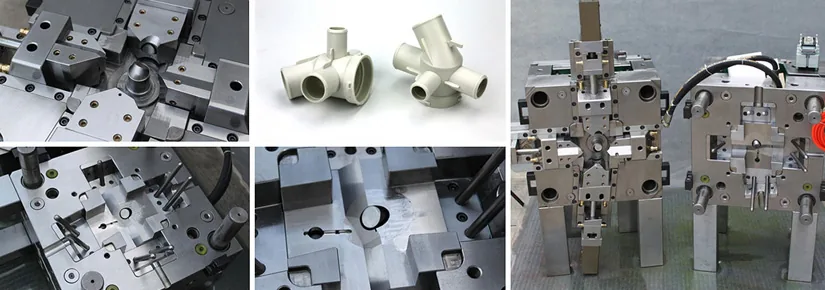
Table of Contents
Introduction
A European appliance OEM came to us with a five-way water manifold that their prototype tool could mold but could not deliver. The part routes water between a dishwasher's pump, heater and spray arms, and it is moulded in POM (acetal) — a material chosen for its stiffness, low friction and dimensional stability in wet service. The catch is the geometry: the press-fit sealing diameters have to be held to ±0.005 mm, and the part carries undercuts on four different pull directions, which no straight-pull mold can release on its own. A manifold like this lives or dies on its sealing geometry: those five press-fit ports are where the pump, heater and spray-arm circuits join, and a diameter that is a few microns out of round is a leak waiting to happen once the assembly is under service pressure.
The prototype tool produced the geometry. That was never the problem. The problem was everything that happened after the fill: ejection dragged the deep ribs, and every trial batch showed deformation on the thick-wall bosses. The press-fit diameters drifted out of the ±0.005 mm gate, so the mold never passed the customer's dimensional gate — and every trial batch ended the same way, with parts that looked right in the cavity and measured wrong on the bench.
They came to DieStrike for a production mold that could do what the prototype could not: release four-direction undercuts without dragging a single feature, hold five press-fit ports round and true, and run at a cycle the customer's takt target could live with. That meant rebuilding the tool's action sequence around hydraulics, splitting the boss geometry into secondary actions, and rethinking how every moving element was cooled.
The Snapshot
Here is the project at a glance — the part, the material, the tool, and the numbers that mattered.
| Part / Component | Five-way water manifold routing water between a dishwasher's pump, heater and spray arms |
| Resin / Material | POM (acetal) |
| Mold / Die Type | Sequential multi-slider injection mold with hydraulic actions |
| Critical Tolerance | ±0.005 mm press-fit sealing diameters |
| Initial Problem | Ejection drag on deep ribs and thick-wall bosses; parts out of the ±0.005 mm gate |
| Result Summary | All five press-fit ports held at ±0.005 mm; cycle time cut 18% |
- Five-way water manifold in POM (acetal), with undercuts on four different pull directions.
- Press-fit sealing diameters held to ±0.005 mm — the gate the prototype tool could not pass.
- Rebuilt action sequence: four hydraulic cylinders, secondary sliders on the bosses, and independent cooling in every slider and lifter.
- Cycle time cut 18%, with the mold planned for 1,000,000+ shots and a documented PM at 500,000 shots.
The Challenge
Three problems stacked up on this program, and each one made the others worse. The first was the geometry itself: undercuts on four different pull directions blocked straight-pull ejection from the start. The previous tool tried to handle them with angled lifters, but that design galled after a few thousand shots — the sliding surfaces wore, the actions bound, and the mold kept coming back to the bench. Four pull directions is not a geometry you can finesse with one clever lifter; it is a sequencing problem, and the old tool never had a sequence — the actions simply moved, in whatever order the machine forced them to.
The second problem was that parts were being deformed by their own ejection. The thick-wall bosses and deep ribs dragged on the core as the part was pushed off, and every drag mark on a boss translated directly into distortion of the press-fit diameters around it. Parts were leaving the mold already outside the ±0.005 mm gate — the customer's dimensional gate was being failed in the ejection stroke, not in the fill, and no amount of process tuning on the machine could fix a part the mold was damaging every cycle. And the rejects were not cheap scrap at the press: the deformation only surfaced once the diameters were gauged, so every bad part had already consumed its share of material, machine time and inspection labor before it was pulled from the batch.
The third problem was cooling. The sliders ran with single-line cooling, which is the norm on quick prototype tooling but a liability on a part like this: the manifold's sealing faces shrank unevenly, and uneven shrinkage across five press-fit ports is exactly the failure mode a water manifold cannot tolerate. On top of that, the slow cooling pushed the cycle above the customer's takt target — the mold was not only making parts that failed the gate, it was making them too slowly to matter even when they passed.
How We Solved It
The rebuild started with the sequence. Four hydraulic cylinders now drive the actions, with a PLC-sequenced opening order: the cavity-side angled lifter releases first, then the four sliders pull in a fixed sequence, so no feature is dragged across another during opening. The part is released in the order its geometry was formed, and because the order is programmable, the sequence can be tuned on the machine instead of reworked on the bench. The action plan was mapped out in our DFM and mold design review before steel was cut — every pull direction, every release order, and every interference risk resolved in the model, not discovered at trial.
The second move was to split the boss geometry. The thick-wall bosses were the deformation source — a single slider dragging across the full boss height every cycle, distorting the press-fit diameters around it. We added secondary sliders on those bosses: the front section releases first, and the trailing section follows, so the steel is never dragging across the full feature at once. Drag marks and ejection deformation were eliminated at the source, and the parts now leave the cavity the way the geometry was designed — not the way ejection forced them to.
The third move was cooling that follows the actions. A slider is a moving block with a small footprint, so it is the easiest thing in a mold to under-cool; the previous tool proved exactly that. Every slider and lifter now carries an independent cooling circuit, balanced against the core circuit so the manifold cools symmetrically on all sides. The sealing diameters stay round through the whole cooling phase, and the faster, even heat removal is what cut the cycle below the customer's takt target. Getting the balance right on an action-heavy tool like this is a core capability across our mold-making operation — the moving elements were treated as first-class cooling zones, not afterthoughts.
The Results
| Sealing diameter tolerance | Held at ±0.005 mm on all five press-fit ports across 250,000-shot sampling |
| Ejection deformation | Eliminated — thick-wall bosses and deep ribs eject clean, no drag marks |
| Cycle time | Cut 18% after per-slider cooling was balanced against the core circuit |
| Mold life | 1,000,000+ shots planned, with a documented PM at 500,000 shots |
The number that matters most to the OEM is the first row: the press-fit sealing diameters are held at ±0.005 mm on all five press-fit ports across 250,000-shot sampling. That is not a first-article measurement or a trial-batch lucky run — it is the gate the prototype tool failed, now held over a quarter of a million shots of production sampling. The dimensional gate that stopped the program is being passed by the parts, not the other way around.
The rest of the table is the operating story. Ejection deformation is gone, which means the drag marks that deformed every boss are gone with it. Cycle time is down 18%, which turns the takt argument around — the tool now runs inside the customer's target instead of above it. And the mold is planned for 1,000,000+ shots, with a documented PM at 500,000 shots, so the program has a maintenance plan rather than a failure date.
Why It Held
Multi-action molds fail on three things: actions that fight each other, features that drag during release, and cooling that never reaches the moving steel. This tool attacked all three at the design stage. The PLC-sequenced opening order means no feature is dragged across another, so the wear that galled the old angled-lifter design after a few thousand shots never gets a chance to start. The secondary sliders take the deformation off the ejection stroke entirely — the bosses are released in two stages, so there is nothing left to drag. And the independent cooling circuits, balanced against the core circuit, keep the sealing diameters round through every phase of the cycle.
The proof is in the sampling: ±0.005 mm held across 250,000 shots, on a mold planned for 1,000,000+ shots with a documented PM at 500,000 shots. That maintenance plan is the honest part of the story — we designed the tool to hold, and we wrote down when to check it so it keeps holding. When the customer's acceptance gate and the toolmaker's verification standard are the same number, there is nothing left to argue about at trial, and nothing to rediscover halfway through the production run.
KEEP READING
Related Reading
Holding Gear Tooth Profile Across an 8-Cavity Mold
Wire-EDM'd S136 inserts and a measured shrinkage loop held gear tooth profile to ±0.02 mm across an 8-cavity POM mold.
Read case studyCase StudySTAVAX ESR Cores for Corrosion-Free Syringe Barrel Molding
Mirror-polished STAVAX ESR cores ended formaldehyde corrosion on a POM syringe barrel mold — 3 cleanroom shutdowns a year to zero.
Read case studyArticlePOM (Delrin) Injection Molding: Complete Guide
What acetal actually does in the mold: shrinkage behavior, moisture sensitivity, and the design rules that keep POM parts dimensionally stable in production.
Read articleArticleHow to Design Undercuts for Automotive Parts
Side actions, lifters and pull directions: how undercut geometry drives mold construction, action sequencing and ejection strategy.
Read articleNEXT STEP
Ready to Start Your Mold?
Send us your element dimensions or part numbers — our team responds within 24 hours with pricing and lead time.

Written by
Ray ChanMold Buyer's Guide Author · Precision Mold Manufacturing Specialist. Ray helps global importers, distributors and OEMs source factory-direct molds and mold parts.