
COC Injection Molding: Material Guide for Optical and Medical Parts
Table of Contents
A diagnostic cuvette molded in cyclic olefin copolymer came out of a T1 trial with visible flow lines near the gate. The optics bench measured transmission at 89% instead of the 91% target, and birefringence failed under polarized light. The resin was optical grade COC, the certificate said so, and the lot was fine. The problem lived in the mold. A 1.2 mm gate jetted into a 2.0 mm wall. The cavity sat at SPI B1 instead of A2, and 0.05 mm vents trapped gas on the optical surface. Three mold-side details destroyed a material that costs 3 to 5 times more per kilogram than polypropylene. COC forgives almost nothing on flow path, surface finish and venting. Every one of those decisions is made in tooling design before steel is cut.
This guide covers COC injection molding from the mold maker's seat. You will get the property numbers that drive tooling decisions, grade selection by Tg, shrinkage and tolerance strategy, and steel and polish selection. Gate and vent geometry, mold temperature windows, thin-wall rules and the trial defect checklist follow. COC sits in the same family of high-clarity amorphous polymers as PMMA and Tritan. Our PMMA optical clarity guide and Tritan mold design guide cover those two. COC needs its own playbook because its water absorption, birefringence behavior and sterilization resistance change the mold math.
The Snapshot
- Light transmission: 91% typical for optical grade COC, among the highest of any thermoplastic.
- Water absorption: under 0.01%, roughly 30 to 40 times lower than PMMA at 0.3 to 0.4%.
- Glass transition (Tg): 70 to 165°C by grade, which sets melt, mold temperature and ejection windows.
- Mold temperature: 60-100°C typical, higher Tg grades run at the top of or above this band.
- Shrinkage: 0.5-0.7% typical, isotropic and low for an amorphous resin, ideal for optical tolerances.
What Is COC and Why Molds Decide Its Optics
COC stands for cyclic olefin copolymer. It is produced by copolymerizing cyclic olefin monomers, usually norbornene type, with ethylene using metallocene catalysts. The result is a fully amorphous, BPA-free polymer with glass-like clarity and a high purity profile. That combination put it into cuvettes, microfluidic chips, syringe barrels, vials, blister packaging and camera lens elements. The closely related cyclic olefin polymer (COP) is a homopolymer variant with similar optics and even lower water absorption.
Two facts define COC for mold designers. First, it is amorphous, so it shrinks little and evenly. That means cavity dimensions translate to part dimensions almost linearly, and warpage stays low if cooling is balanced. Second, it is extremely sensitive to flow history. Any shear spike, gas pocket or cold surface contact gets frozen into the glassy structure as birefringence or a flow mark. The material records every mold decision you make.
That sensitivity is why COC tooling cost trends higher than for PMMA or Tritan at the same cavity count. Optical surfaces need SPI A1-A2 polish and vents need tighter depth control. Gates need flow simulation, and mold temperature circuits must hold 60-100°C within a few degrees across the cavity. For a mold buyer, the practical rule is simple: with COC, the process window lives in the steel. Mold flow simulation pays for itself on these tools, and COC optical parts are a textbook case.

COC demand keeps climbing for two reasons. Medical diagnostics moved to disposable optical cartridges that read fluorescence and absorbance, and those cartridges need 91% transmission with near-zero water uptake. Optics makers use COC where PMMA fails on humidity stability and where glass fails on weight and cost. Both applications put the mold at the center of part quality, not the resin supplier.
COC Key Properties: Numbers That Drive Mold Design
Every property below feeds a specific mold decision. We list the numbers first, then what they change in tooling. Values are typical industry figures for optical and medical grade COC, and actual data depends on the grade you buy.
Optical properties. Transmission is 91% typical in the visible range and haze stays under 1% for optical grades. Birefringence is low, often below 100 nm retardation in well-gated parts. Low birefringence is COC's headline advantage over polycarbonate, which is notoriously stress-birefringent. In the mold, this means surface finish, gate location and fill balance are the three levers that decide whether the part passes a polariscope check.
Moisture and purity. Water absorption is under 0.01%, the lowest of the common clear polymers. PMMA absorbs 0.3-0.4% and PC about 0.15-0.35%. COC parts do not swell or fog with humidity, which is why diagnostic cartridges keep optical calibration in storage. Mold-side consequence: COC needs little or no drying, so no desiccant loop is required. The material will not splay from moisture the way nylon or PC does.
Thermal behavior. Tg runs from 70 to 165°C by grade. Melt temperature windows span roughly 230 to 290°C for mid-Tg grades, and high-Tg grades above 145°C need 290-320°C. Density is about 1.02 g/cm³, lighter than PMMA at 1.19 and PC at 1.20. A COC lens weighs roughly 14% less than the same PMMA lens. Thermal stability is good, but COC degrades if held above 330°C, which caps hot runner soak temperatures.
Mechanical profile. Tensile strength is 45-70 MPa depending on grade, modulus 2.5-3.5 GPa, and elongation at break 2-30%. COC is stiffer and harder than PMMA but not tougher, and it is brittle at thin sections with sharp corners. Mold rule: minimum fillet radius 0.5 mm or 25% of wall, never a sharp internal corner. Stress concentrators crack parts and show up as birefringence halos.
Chemical and sterilization resistance. COC resists polar solvents, acids and bases, and it survives gamma at 25-50 kGy, EtO and steam depending on grade. It is BPA-free and halogen-free, and medical grades carry USP Class VI and ISO 10993 data from the resin maker. Compliance paperwork belongs to the molder and material supplier, and our medical injection molding guide covers the full documentation chain.
| Property (typical figures) | COC | PMMA | Tritan | PC | Glass (borosilicate) |
|---|---|---|---|---|---|
| Light transmission | 91% | 92% | 90% | 88-89% | 92-93% |
| Water absorption | <0.01% | 0.3-0.4% | 0.3% | 0.15-0.35% | 0% |
| Tg / max service temp | 70-165°C by grade | ~105°C | ~109°C | ~148°C | 500°C+ |
| Density (g/cm³) | 1.02 | 1.19 | 1.12 | 1.20 | 2.23 |
| Mold shrinkage | 0.5-0.7% | 0.4-0.7% | 0.5-0.7% | 0.5-0.7% | N/A |
| Birefringence risk | Low | Low-moderate | Low-moderate | High | Very low |
| Gamma sterilization | Good (grade dependent) | Poor (yellows) | Fair | Fair (yellows) | Excellent |
← swipe to scroll →
Table note: typical industry figures for optical and medical grades, not datasheet values for a specific lot. Verify against your resin supplier's data sheet before cutting steel.
The comparison explains COC's market position. Glass wins on thermal and chemical extremes but costs 10 to 30 times more per finished part and breaks. PMMA matches transmission but absorbs 30 times more water and yellows under gamma. PC is tough but birefringent and hydrolyzes. COC takes the optical and medical middle ground. The mold must deliver the surface and flow quality that makes those numbers real in the part.
COC Grade Selection by Glass Transition Temperature
Commercial COC grades are organized around Tg, and Tg sets almost every mold parameter you choose. Major suppliers line up from about 70°C to 165°C. Low-Tg grades around 70-80°C flow the easiest and suit packaging film blends and low-cost optics. Mid grades at 100-115°C are the workhorses for cuvettes, lenses and diagnostic housings. High grades at 134-165°C survive autoclave and hot-fill duty but demand hotter processing.
Melt window follows Tg. As a rule of thumb, COC injection melt temperature sits 100-130°C above Tg. A 102°C grade processes around 230-260°C. A 158°C grade needs 290-320°C. That high end crosses into high-temperature resin tooling territory, so hot runner heaters, thermocouple placement and steel hardness all get re-specified above 300°C.
Mold temperature follows Tg. Cavity surface temperature usually lands 10-30°C below Tg for dimensional control and ejection. For a mid grade with Tg around 102°C, that puts the mold at 70-90°C, inside the 60-100°C band most COC jobs use. High-Tg grades push mold temperature to 100-130°C, which changes cooling circuit design from simple water lines to oil or pressurized water circuits.
Ejection timing follows Tg. The part demolds safely once it drops about 20-30°C below Tg. A 70°C grade can eject at roughly 100-120°C part temperature, so cycles stay short. A 165°C grade must cool to 135°C before ejection or it deforms, and that drives cycle time up by 30-60 seconds on thick sections. Cooling channel density, not injection speed, decides your cycle on high-Tg COC.
Flow grades exist for thin walls. High-melt-flow COC grades reach 30-70 g/10min MFI and fill 0.5 mm walls that standard grades cannot. If your diagnostic cartridge has 0.6 mm ribs or a channel below 0.5 mm, specify the high-flow grade. Re-check birefringence, because high shear flow raises frozen-in stress. Micro molding tooling rules cover the sub-gram end of this problem.
Pick the grade from the sterilization method first, the service temperature second and the wall thickness third. A gamma-sterilized cuvette at 25 kGy works with a mid-Tg grade. An autoclaved tray at 121°C needs Tg of 145°C or higher. A 0.5 mm blister needs a low-Tg high-flow grade. Grade choice then locks your melt window, mold temperature, cooling design and cycle time before any CAD is drawn.
Shrinkage and Mold Tolerances for COC
COC shrinkage is 0.5-0.7% typical, and for an amorphous resin that number is unusually stable. Flow direction and transverse shrinkage differ by only about 0.1%, which means molded optics do not twist the way glass-filled or semi-crystalline parts do. For a 25 mm lens diameter, 0.6% shrinkage equals 0.15 mm of cavity growth. A good mold holds that within a ±0.01 mm lot-to-lot band.
Three variables move COC shrinkage in production. Mold temperature is the biggest: raising cavity temperature from 60 to 90°C typically adds 0.05-0.1% shrinkage because the frozen layer thins. Packing pressure contributes another ±0.05% across a normal window. Gate freeze time matters on thin parts, since COC freezes fast and under-packing shows up as a dimensional shift within a few shots.
Tolerance strategy. For optical features, hold mold tolerances at ±0.005 mm on critical dimensions, which is the standard DieStrike applies to key mold sizes. Cavity geometry itself is machined to ±0.002 mm where the optical datum lives. Achieving that requires hardened and ground or EDM'd inserts, not soft-milled pre-hard steel, plus a machine, fixturing and measurement chain that holds that band.

Post-mold movement is minimal. Because COC absorbs under 0.01% water, parts do not grow after ejection the way nylon parts swell by 0.2-0.4%. Dimensional readings taken at 24 hours are effectively final. That is a real advantage for medical validation, where IQ/OQ/PQ protocols want stable first-article data.
Warpage control is a cooling problem. With isotropic shrinkage, COC warps mainly from asymmetric cooling, not from material anisotropy. Keep coolant-to-cavity distance equal within 1 mm between core and cavity sides, and keep the temperature delta between circuits under 5°C. On flat optical windows thicker than 3 mm, a core-side circuit that runs 10°C hotter produces a measurable crown in the part.
Mold Steel and Surface Finish for COC Optics
Optical COC surfaces replicate the steel exactly. A cavity at SPI A1 with a surface roughness near Ra 0.012 µm produces a polished, mirror-like part. SPI A2 at roughly Ra 0.025 µm is the common target for diagnostic windows and lenses. Anything coarser than SPI B1 starts scattering light, and the 91% transmission number quietly becomes 87% in the assembled device.
Steel selection. Through-hardened stainless mold steels such as S136 or 420-class stainless at HRC 50-54 take and hold an A1 polish. Pre-hardened steels like P20 at HRC 30-34 can reach A2-B1 but polish unevenly because of their banded microstructure. For production runs beyond 500,000 shots, harden the optical inserts to HRC 52+ or coat them. COC is abrasive-free, but the polish degrades with repeated cleaning. The mold polishing guide walks from Ra 3.2 to SPI A1 in stages.
Polish direction and EDM. Optical surfaces should be hand-polished in one consistent direction, and the final stage uses diamond paste at 1 µm or finer. EDM'd surfaces carry a recast layer that must be fully removed, typically 0.02-0.05 mm of stock, before polishing starts. Skipping that step leaves micro-craters that show up as haze under the lens test. Where the geometry allows, hard milling followed by light polishing beats EDM plus heavy rework on optical faces.
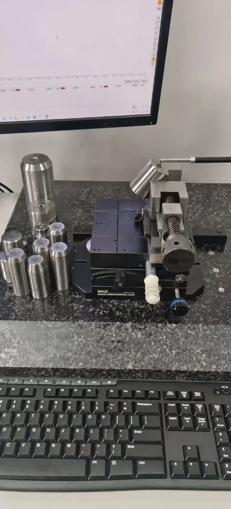
Corrosion resistance matters for medical runs. Medical COC molds see frequent cleaning, sterilization cycles of the tool inserts, and moisture from 80-100°C coolant circuits. Stainless cores and cavities resist the pitting that carbon steels develop within months. DieStrike cuts cavity steels to HRC 62 on hardened components where wear demands it. The shop runs an IATF 16949 quality system across 120+ machines for tooling of this class.
Vent land finish. The last 1-2 mm of vent land next to the optical surface needs the same polish as the cavity. Any tool mark there becomes a witness line on the part. Specify the finish requirement on the vent land explicitly in the mold drawing. This detail is missed on most first-time optical tools.
Gate Design for COC: Flow Marks and Birefringence
COC is a high-flow, shear-sensitive resin. It fills thin walls easily but freezes stress into the part at the gate. The opening scenario, a jetted 1.2 mm gate leaving flow lines, is the most common COC gate mistake we see at T1. Gate design is the single biggest mold-side lever for both cosmetics and birefringence.
Edge gates with a tab. For optical windows and flat parts, use an edge gate feeding a land or tab of 2-3 times the wall thickness. The tab converts the jet into controlled laminar flow and localizes the high-stress zone where it can be trimmed or hidden. Gate depth should be 50-70% of nominal wall. The transition into the cavity needs a radius of 0.5 mm or more to avoid a shear spike.
Valve-gated hot runners for medical parts. Diagnostic cartridges and vials in high-cavity molds run best on valve gates. A valve pin shears the melt once, cleanly, and leaves a controlled gate witness with no drool and no stringing. Cold runner COC scrap is expensive, since optical grades cost roughly $15-30 per kilogram. Hot runners pay back fast above 50,000 shots.
Gate location versus optics. Never place a gate where a polariscope will see the flow front converge across an optical path unless you can control the weld. In cuvettes, the light path crosses the sidewalls, so gates belong on the top rim or bottom corners. Simulate the fill first. COC weld lines show birefringence more clearly than strength problems. A weld line in the read path can fail an optical inspection even when the part is structurally fine.

Fill speed profile is set by geometry. Because the mold cannot change injection speed, the gate and runner geometry must do the work. Keep runner diameters at 5-8 mm for cold runners and avoid abrupt diameter jumps. Balance multi-cavity layouts so every cavity fills within 0.2 seconds of the others. Unbalanced fill creates cavity-to-cavity birefringence variation that kills yield in 16-cavity cartridge molds. Runner, gate and cooling balance must be designed together.
Venting Rules for High-Flow COC Resins
COC flows fast and reaches the last-fill corners before the air does. Without adequate venting, trapped gas compresses, heats adiabatically to several hundred degrees, and burns the surface or blocks the fill entirely. In optical parts, even a micro-burn is scrap, because the affected zone scatters light. Vent design for COC is tighter than for commodity resins.
Vent depth. COC's viscosity at fill speed allows vent depths of 0.02-0.03 mm without flash, which is shallower than the 0.03-0.05 mm typical for ABS or PP. Cut vents at 0.025 mm on optical faces and land them 1-2 mm before opening to a 0.5-1.0 mm relief pocket. On the opening cuvette, the 0.05 mm vents flashed slightly while still trapping gas at the last fill, the worst of both outcomes.
Vent location. Place vents at every last-fill corner, along parting lines opposite the gate, and around ejector pins and core pins that fill last. Ejector pin vents at 0.02 mm clearance on the pin body give continuous evacuation. Insert shut-offs need vent channels too, because COC's fast fill leaves air nowhere to go in deep narrow pockets.
Parting line flatness. Vents only work if the shut-off around them seals. On a COC optical mold, hold parting line flatness to 0.01 mm across the shut-off band. Otherwise the 0.025 mm vents become 0.06 mm gaps under clamp deflection. That flatness level requires grinding after heat treatment, and it is a line item buyers should see in the mold quote. Thin vents plus loose shut-offs equal flash plus burns simultaneously.
Vacuum venting for deep parts. Vials, syringe barrels and cartridges with high aspect ratios benefit from cavity vacuum at 0.05-0.1 bar absolute before fill. Vacuum removes 90%+ of trapped gas and lets you slow the fill, which lowers shear birefringence. It adds a mold sealing requirement: O-ring grooves around the cavity block and hardened shut-offs that survive thousands of clamp cycles.
Mold Temperature and Cooling at 60-100°C
COC does not mold in a cold tool. A cavity below 60°C freezes the skin instantly, traps stress and produces dull surfaces with high birefringence. The practical band is 60-100°C for standard and mid-Tg grades, and 100-130°C for high-Tg medical grades that must survive autoclave. Every degree matters: a 10°C swing on the optical face shows up in gloss and internal stress.
Circuit design. At 80°C mold temperature, plain water circuits work if flow stays turbulent, above roughly 1.5 m/s in a 10 mm channel. High-Tg grades above 110°C need pressurized water or oil circuits and controllers rated accordingly. Place circuits 15-25 mm from the cavity surface on optical faces, closer than the 30-40 mm typical for commodity molds. You are managing a uniformity requirement of ±2°C, not just heat removal.
Uniformity beats speed. On a cuvette with four optical walls, one hot spot of 15°C on a single wall produces a visible refractive gradient in the light path. Use baffle or bubbler inserts in cores to equalize cooling. Measure cavity surface temperature with an IR gun at trial before trusting the controller readout. Size the mold temperature controller for 100-130°C service on high-Tg jobs, with enough pump head for turbulent flow in every circuit.
Cycle time reality. A 2 mm mid-Tg COC wall cools to ejection temperature in about 12-18 seconds. A full cycle of 25-35 seconds is normal for a 4-cavity cartridge mold. High-Tg grades with Tg near 160°C need part temperatures below 130°C at ejection, which stretches cooling to 30-50 seconds on the same wall. Cooling, not filling or packing, dominates your piece price on COC. Conformal-cooled inserts cut that time 20-40% on thick sections, and the payback is fastest exactly where resin costs are highest.
Scale and maintenance. Running circuits at 80-120°C for months deposits scale inside channels and steals heat transfer. A 1 mm scale layer can drop effective cooling by 30% or more, which quietly shifts mold temperature and, with it, COC shrinkage. Schedule descaling and verify flow rates at every PM. Keeping optical dimension stability on a COC mold is half cooling maintenance.
Thin-Wall COC Parts at 0.5 mm
Microfluidic chips, diagnostic membranes and blister cavities push COC walls down to 0.5 mm and below. COC is one of the few clear polymers that fills these walls reliably, thanks to high-flow grades at 30-70 g/10min MFI and low melt viscosity. Filling is only half the problem, ejection and warpage are the other half.
Fill length to thickness ratio. High-flow COC reaches flow ratios of about 100:1 to 150:1. A 0.5 mm wall can fill roughly 50-75 mm from the gate with adequate melt and mold temperature. Standard flow grades top out near 80:1. Design the gate position so the longest flow path stays inside 60% of that limit. The margin disappears as mold temperature drifts down 10°C during a long run.
Thickness transitions. Thin COC walls crack at sharp steps. Keep wall transitions at a 3:1 taper minimum and radius every corner at 0.3-0.5 mm even on 0.5 mm sections. Brittle thin sections plus sharp corners equal cracked parts at ejection. Those cracks often appear hours later as stress relaxation, which is worse for the yield report.
Ejection and draft. Use 1.0-1.5° draft on thin walls instead of the 0.5° that thicker parts accept, because stripping force per unit area rises as stiffness falls. Blade ejectors or stripper plates beat pins on flat thin parts. A 4 mm diameter pin on a 0.6 mm wall punches through at ejection temperature. Spread the ejection force over the widest area the geometry allows, and keep ejection speed slow and steady.
Warpage on flat thin sections. A 0.5 mm optical window 40 mm across will dish if cooling is asymmetric by even 3°C. On microfluidic chips, dishing of 0.1 mm breaks the seal against a gasket or cover. The fix is in the mold. Match coolant distance on both halves and mirror identical circuit layouts across the parting line. Give each half its own temperature controller so every face is tuned independently.
Sterilization Resistance and Mold Decisions
Medical COC parts get sterilized after molding, and the method chosen by the device team reaches back into the mold design. Gamma, EtO and steam each impose different requirements on the molded surface and the dimensional stability of the part.
Gamma at 25-50 kGy. COC handles gamma better than PMMA or PC, with minimal yellowing on stabilized medical grades. Gamma does not attack the mold, but it relaxes frozen-in stress in the part. Birefringence patterns locked in by a badly placed gate can shift after irradiation, changing optical performance. That is why gate design must be right before validation, not after. A part that passes optics pre-gamma can drift post-gamma if residual stress is high.
EtO. Ethylene oxide sterilization runs at 40-60°C and leaves residues that need aeration. COC's near-zero water absorption helps here, because it also absorbs little EtO, so aeration times run shorter than porous materials. No mold impact beyond the usual surface quality requirement.
Steam and autoclave. Repeated autoclaving at 121-134°C demands a Tg above the sterilization temperature by at least 15-20°C, which means high-Tg grades of 145-165°C. Those grades push mold temperature to 100-130°C and change the whole tooling specification, hotter steel, better heaters, longer cooling. If the device spec says autoclave, tell your mold maker at RFQ stage, not at T1. A mid-Tg mold cannot be retrofitted into a high-Tg process window cheaply.
Parting line and ejector marks on medical surfaces. Sterile parts cannot tolerate flash, because flash traps bioburden and sheds particles. That raises the bar on shut-off precision and mold maintenance intervals. Specify ejector pin locations away from sealing surfaces and functional faces. Budget for pin polishing or DLC-coated pins where thousands of cycles would leave witness marks. Those marks fail visual inspection under the device standard.
Common COC Molding Defects and Mold-Side Fixes
COC defects follow repeatable patterns, and nearly every one traces back to a mold feature rather than a machine setting. The list below is what we check first when a COC tool fails at trial, ordered by how often it appears.
Flow marks and jetting. Cause: gate too small or opening straight into a thin cavity. The melt snakes instead of spreading. Mold fix: tab gate or fan gate, gate depth at 50-70% of wall, radius 0.5 mm minimum at the gate exit. On the opening cuvette, enlarging the gate from 1.2 mm to a 2.5 mm fan with a 3 mm tab removed the flow lines entirely.
Birefringence halos. Cause: high shear at gates, sharp corners or unbalanced fill freezing stress into the optical path. Mold fix: relocate gates away from the read path, radius every corner, balance runners so cavities fill within 0.2 seconds. Inspect every T1 sample under a polariscope, not just the naked eye, because halos below about 100 nm retardation are invisible until assembly.
Burns at last fill. Cause: vents deeper than 0.03 mm flashing while still trapping air, or vents missing at last-fill corners. Mold fix: recut vents to 0.025 mm with proper land length, add ejector pin vents, or install cavity vacuum for deep parts.
Dull or hazy optical surfaces. Cause: mold temperature below 60°C, or polish coarser than SPI A2, or EDM recast layer left in place. Mold fix: raise mold temperature into the grade window, re-polish to A1-A2 with full recast removal of 0.02-0.05 mm.
Ejection cracking on thin walls. Cause: pins too small for 0.5-0.8 mm walls, draft below 1.0°, ejection too fast at high part temperature. Mold fix: blade ejectors or stripper plates, 1.0-1.5° draft, and ejector speed limited on the machine interface specified at mold buy-off.
Dimensional drift across a run. Cause: mold temperature swing of more than 5°C, or scaled cooling channels losing heat transfer. Mold fix: verify controller stability and channel flow at each PM, and log cavity surface temperature at start, middle and end of the run. On COC, a 5°C drift moves shrinkage about 0.05%, which is 0.01 mm on a 20 mm feature, often the entire tolerance band.
The pattern is consistent: with COC, defect fixes are mold fixes. Process windows on this material are narrow enough that a well-built tool defines quality. A badly built one cannot be rescued by adjusting the machine. Budget trial time accordingly. A COC optical mold typically needs T1 through T3 to close optics, vents and dimensions together. Plan sampling rounds into the lead time from day one.
FAQ: COC Injection Molding
Q1. Is COC more expensive to mold than PMMA or PC?
The mold typically costs 10-25% more than a PMMA tool of the same size. SPI A1-A2 polish, tighter 0.02-0.03 mm vents and hotter 60-100°C cooling circuits drive that gap. Resin costs more too, at roughly $15-30 per kilogram for optical grades versus $3-5 for PMMA. The premium buys 91% transmission with under 0.01% water absorption and gamma resistance.
Q2. What mold temperature does COC need?
Standard and mid-Tg grades run at 60-100°C, and high-Tg grades of 145-165°C need 100-130°C. As a rule, set cavity temperature 10-30°C below the grade's Tg. Below 60°C the surface freezes dull and birefringence spikes, above the window the part sticks and deforms at ejection.
Q3. Can COC parts be autoclaved?
Yes, with the right grade. Repeated steam sterilization at 121-134°C requires Tg of about 145°C or higher, so specify a high-Tg COC grade. Those grades also force hotter mold temperatures and longer cooling. Declare the sterilization method at RFQ stage, not after the tool is cut.
Q4. Does COC need drying before molding?
Almost never. Water absorption is under 0.01%, so COC is essentially hydrophobic and ships dry. Most grades need only 2-4 hours at 80-90°C if bags sat open, versus 4 hours at 120°C for PC or 12 hours for nylon. Check the datasheet, but drying is rarely the bottleneck on COC jobs.
Q5. What polish do optical COC cavities require?
SPI A2 minimum for diagnostic windows, SPI A1 for imaging optics and lens surfaces. That means through-hardened stainless like S136 at HRC 50-54, hand-polished with diamond paste at 1 µm or finer. Remove any EDM recast layer of 0.02-0.05 mm first. P20 can reach A2 at best and polishes unevenly.
The Bottom Line
COC delivers 91% transmission and sterilization resistance only if the mold is built for it. SPI A1-A2 polish, 0.02-0.03 mm vents, tab or valve gates and 60-100°C cooling decide whether datasheet numbers reach the part. DieStrike builds precision molds to ±0.005 mm with DFM feedback in 24 hours.
Contact us with your COC part drawing for a mold-side review.
KEEP READING
Related Reading
Mold Polishing Guide: From Ra 3.2 to SPI A1
How polish grades map to optical surface quality and what each SPI finish costs in mold hours.
Read articleArticleMold Venting: Depth, Location and Design Rules
Vent depth rules that prevent burns and short shots in high-flow resins like COC.
Read articleArticleHow to Design Molds for High-Temperature Resins
Tooling rules for PPS, PPA, PEEK and PEI, useful when a COC grade pushes melt above 300°C.
Read articleServiceInjection Mold Manufacturing
IATF 16949 precision injection molds held to ±0.005 mm with 2-5 week lead times.
Read articleNEXT STEP
Ready to Start Your Mold?
Send us your element dimensions or part numbers — our team responds within 24 hours with pricing and lead time.

Written by
Ray ChanMold Buyer's Guide Author · Precision Mold Manufacturing Specialist. Ray helps global importers, distributors and OEMs source factory-direct molds and mold parts.